- Connecting a two-gang light switch with a socket: decoding the circuit
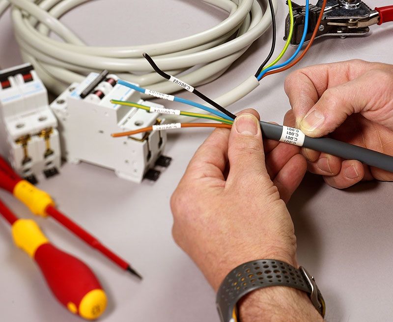
- Connecting a two-gang switch: preparatory work
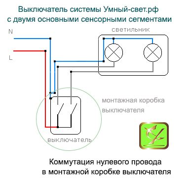
- Illuminated two-gang switch
- Materials required for installation
- Device
- with diode
- With capacitor: to save electricity
- A device that controls two groups of luminaires
- What are the advantages of two-gang switches?
- Prices for adjustable switches
- 6 Illuminated two-gang switches: independent connection
- Let's start with a simple one: a diagram for connecting a single-gang switch to a light bulb
- How does the separate power supply of the chandelier work?
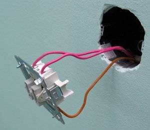
- The final stage - we put the wires in the switch
Connecting a two-gang light switch with a socket: decoding the circuit
In order to properly install the unit in which the socket and the switch button are combined, it is necessary to act according to the diagram below.
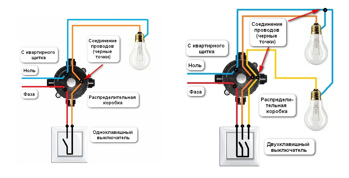
Wiring diagram for a two-key switch with a socket (unit with 1 key)
The algorithm of actions is as follows:
- a cable with two cores is removed from the main shield: phase and zero. It connects to the contacts in the junction box. By means of a double cable, a lamp and a switch with a socket are connected;
- three cables coming out of the installed unit come into the junction box.The luminaire is connected with one core to zero, and the second to the free terminal of the switch;
- if a grounding conductor is provided in the "socket + switch" block, it must be connected to the same conductor in the junction box.
Connecting a two-gang switch: preparatory work
It is worth noting that before you connect the light switch, which is double, you need to lay the wiring. If the house is just being built and hidden wiring is carried out in it, then there are no difficulties. The wiring itself is installed even before the plaster is applied.
After that, you need to connect the switch itself and the fixtures to the wiring. All wires are laid according to the diagram (see below).
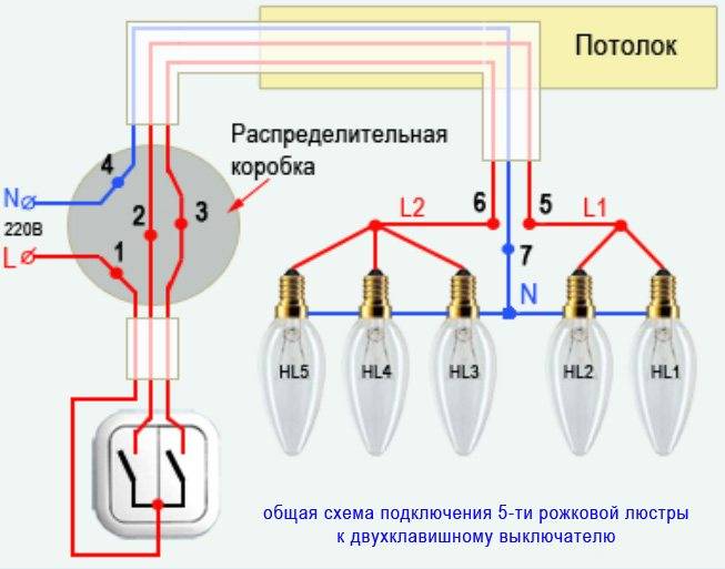
The two-gang switch is designed to turn on and off two electrical appliances from one place or control individual sections of one appliance.
Most often, such switches are used to switch the operating modes of the chandelier: each of the two keys turns on one of the two groups of lamps, and when both keys are turned on, the entire chandelier is connected completely.
Using this switch, you can control the illumination of the room. Also, the use of a light switch with two keys is useful for turning on the lighting of a separate bathroom and toilet.
It’s actually not as difficult to draw up a connection diagram for a two-lamp switch as it might seem at first glance. If this is a private house, connecting a double light switch will be convenient for lighting the street when leaving. If it is possible to use a lighting device with a two-gang switch on the balcony, the presence of the device there will also be appropriate.
Each group can have a different number of light bulbs - it can be either one or ten or more lamps. But a two-gang switch can only control two groups of lamps.
It is clear that if it is planned to carry out open wiring, then each cable that needs to be connected to a two-gang switch and a lamp is laid in separate cable channels or corrugated pipes.
If the wiring in the house has been used for many years, and the existing electrical wires are not suitable, then they will need to be replaced. In the event that they were mounted in an open way, there will be no problems. If they were hidden under plaster, you will have to make new strobes and lay new cables. After placing the cables in their places, proceed to connect them.
Before starting work on replacement of electrical wiring in the apartment or a private house and the installation of a two-gang switch for safety reasons, the power supply should be completely turned off.
To do this, it will be enough to turn off the automatic switch, which is at the beginning of the circuit designed to supply current to the lighting fixtures.
And so, when all the preparatory work is done and the wires are placed according to the diagram, you can start connecting the two-gang switch.
How to connect a switch with two keys
Illuminated two-gang switch
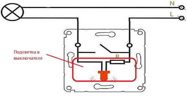
A backlit switch differs from a conventional one only in that it contains a backlight indicator. This indicator can be a neon lamp or an LED with a limiting resistor. The backlit switch circuit is quite simple.


The indicator is connected in parallel with the switch terminals.When the light switch is turned off, the backlight indicator is connected to the neutral wire of the network through a small lamp resistance and lights up. When the lighting is turned on, the indicator circuit is short-circuited and it goes out.
- The wiring diagram for the illuminated switch is based on the following sequence of actions:
- the lighting circuit is de-energized. For reliability, the absence of voltage is checked with a probe or multimeter;
- a box for the switch is installed and fixed in the opening in the wall. When replacing the old one, it is first dismantled;
- the key is removed from the switch and the power wires are connected. In parallel with the cables, the outputs of the backlight indicator are connected;
- the switch body is installed in the box and fixed with screws;
- the network is turned on and the operability of the switch, its backlight and the lighting network are checked.
Materials required for installation
- To make a connection, you need:
- Electrical wires (the cross section must be at least 1.5 square millimeters). Their length is determined by measurements.
- Double switch.
- Mounting box in which the switch will be placed.
- Terminal blocks.
- Tape.
- Tools
- As for tools, their list should consist of:
- screwdrivers for cross and flat slots;
- a mounting knife or a device with which insulation will be removed;
- side cutters;
- level;
- pliers;
- hammer and chisel (in case you need to make a small strobe or hole for the socket).
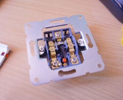
Device
Connecting a light switch is a simple procedure, but it is worth knowing how to choose a quality model or how to remake what is already in stock. The backlight in the switch is usually a series connection of an LED/neon lamp with a resistor. This small circuit is connected in parallel with the switch contact. It turns out, regardless of whether the light is on or off, this circuit is energized all the time.
With this connection, when the lighting is turned off, the following circuit is created: the phase goes through a current-limiting resistor, flows through an LED or a neon lamp, goes through the connection terminals to a light bulb, and through an incandescent filament to neutral. That is, the backlight is on.
When the switch is on, the backlight circuit is shunted by a closed contact, the resistance of which is much less. The current through the backlight almost does not flow, it does not burn (it can burn in a third or a quarter of the "glow").
The principle of operation of the backlight in the switch
As already mentioned, a current-limiting resistor (resistance) is installed in series with the LED or neon lamp in the switch. Its task is to reduce the current to an acceptable value. Since LEDs and neon lamps require a different amount of current, the resistors are set to different values:
- for neon 0.5-1 MΩ and power dissipation 0.25 W:
- for LEDs - 100-150 kOhm, power dissipation - 1 W.
But connecting the LED backlight only through a resistor is not the best option. First, the resistor gets very hot. Secondly, with such a connection, there is a possibility that a reverse current may flow through the circuit.This can lead to breakdown of the LED. Thirdly, in models with LED backlighting, the power consumption of one switch can exceed 300 W per month. It seems like a little, but if the backlight is on each key of each switch ... There are more economical and safe schemes for backlighting the switch keys.
with diode
First of all, it is worth solving the problem of reverse current. Reverse current threatens to breakdown the LED, that is, the backlight will be inoperative. This problem is solved very simply - by installing a diode in parallel with the LED element.
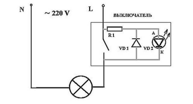
Illumination option in the electric switch
With this scheme, the dissipated power of the resistor is at least 1 W, the resistance is 100-150 kOhm. The diode is selected with parameters similar to those of the LED. For example, for AL307, KD521 or analogues are suitable. The disadvantage of the circuit is still the same: the resistor heats up and the backlight “pulls” a lot of energy.
With capacitor: to save electricity
To solve the problem of a heating resistor and reduce the cost of backlighting, a capacitor is added to the circuit. The parameters of the resistor also change, since now it limits the charge of the capacitor. The schema looks like this.
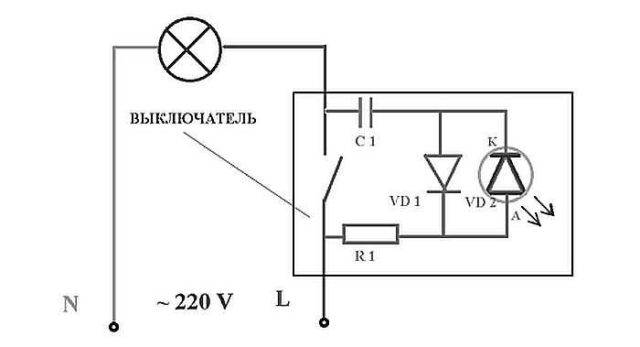
Illumination circuit of the switch keys with a capacitor
Resistor parameters - 100-500 OM, capacitor parameters - 1 mF, 300 V. Resistor parameters are selected experimentally. Also, in this circuit, instead of a conventional diode, you can put a second LED element. For example, on the second key or on the opposite side of the case.
Such a scheme practically does not "pull" electricity. Monthly consumption - about 50 watts. But placing a capacitor in a small space of the case is sometimes problematic. And work with LED and energy-saving lamps is still not guaranteed.
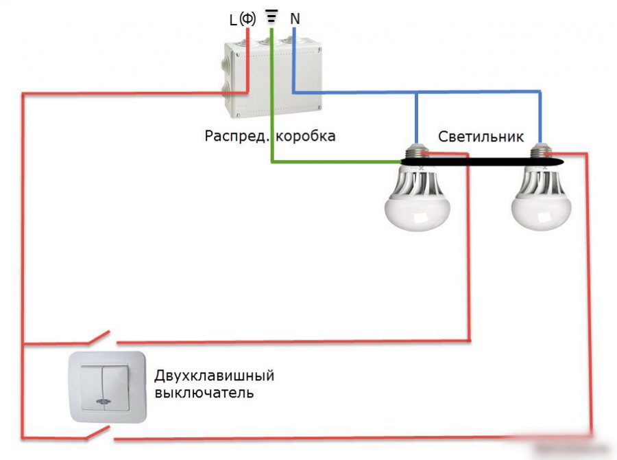
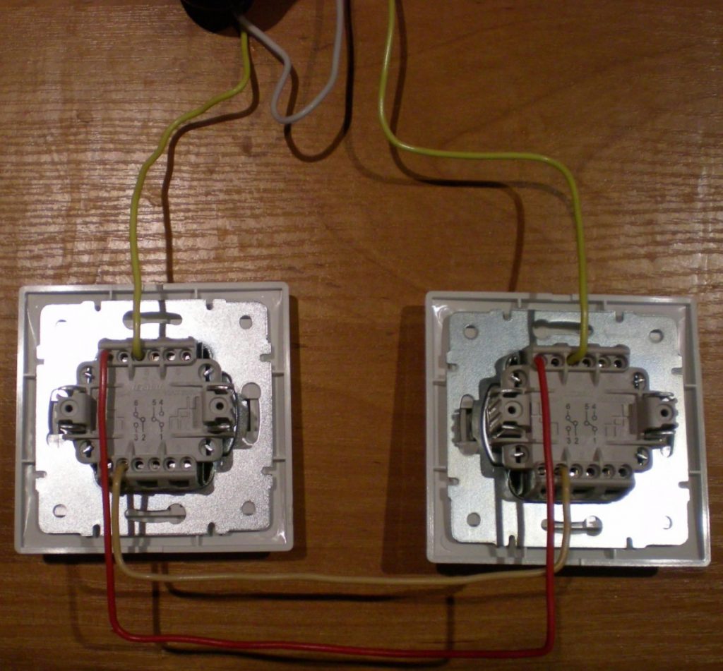
A device that controls two groups of luminaires
Wiring diagram for two-button walk-through switches
It is advisable to install a two-gang pass-through switch in a large room where it is necessary to control several lighting fixtures. Its design consists of two single switches in a common housing. Mounting one device to control two groups allows you to save on laying the cable to each of the single-gang switches.


Mounting a double pass switch
Such a device is used to turn on the light in the bathroom and toilet or in the corridor and on the landing, it is able to turn on the light bulbs in the chandelier in several groups. To install a pass-through switch designed for two light bulbs, you will need more wires. Six wires are connected to each, since, unlike a simple two-gang switch, the pass-through switch does not have a common terminal. In essence, these are two independent switches in one housing. The switching circuit of a switch with two keys is performed in the following sequence:
- Socket outlets for devices are installed in the wall. The hole for them is cut with a puncher with a crown. Two wires with three cores are connected to them through the strobes in the wall (or one six-core wire from the switch box).
- A three-core cable is connected to each lighting fixture: neutral wire, ground and phase.
- In the junction box, the phase wire is connected to the two contacts of the first switch. Two devices are interconnected by four jumpers. Contacts from lamps are connected to the second switch. The second wire of the lighting fixtures is switched with zero coming from the switchboard.When switching contacts, the common circuits of the switches close and open in pairs, ensuring that the corresponding lamp is turned on and off.
Connecting a cross switch
Two-gang switches are also used, if necessary, to control lighting from three or four places. A double cross-type switch is installed between them. Its connection is provided by 8 wires, 4 for each limit switch. For installation of complex connections with many wires, it is recommended to use junction boxes and mark all cables. A standard Ø 60 mm box will not accommodate a large number of wires, you will need to increase the size of the product or supply several paired or purchase a Ø 100 mm junction box.
Wires in junction box
It is important to remember that all work with electrical wiring and installation of devices is carried out with the power turned off. This video tells about the device, the principle of connection and installation of pass-through switches:
This video tells about the device, the principle of connection and installation of pass-through switches:
This video shows an experiment in which various ways of connecting wires were tested:
Wiring diagram
The principle of connecting switches
Wiring diagram for a two-gang switch with connection through a junction box
Everything is written correctly in the article, but I came across the fact that the electrician who installed the switches before did not leave spare wires in the box, and when one aluminum wire broke, I had to tinker with building this wire. I advise you to leave a margin for at least two repairs.
I myself studied to be an electrician and sometimes I work part-time as an electrician. But every year, or even every month, more and more electrical questions are being created. I work on private calls. But your published innovation is new to me. The scheme is interesting and will definitely come in handy in the near future. I always try to take the advice of "experienced" electricians.
What are the advantages of two-gang switches?
In size, double models do not differ from single ones. This is convenient if it becomes necessary to replace one with another.
Switches differ in their device. The working part of the double includes three contacts: one at the input and two at the output. It is the outgoing contacts that control the operation of two independent light sources (or groups).


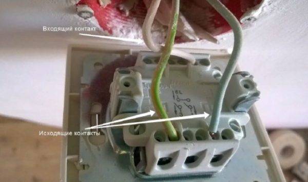
Incoming and outgoing contacts
The installation of switching devices having 2 keys has its advantages.
- When installing two single-key models, it is necessary to pull the cable to each of them. Accordingly, their replacement with one device leads to a reduction in labor costs and savings in materials.
- Two separate light sources can be connected to different keys and their operation can be controlled from one point. For example, this is convenient when outputting contacts from fixtures in the toilet and bathroom, if they are located nearby. Moreover, in accordance with the PUE, it is allowed to place switches only outside these premises. In the same way, it is possible to configure the inclusion of different groups of spotlights. They can be switched on alternately or simultaneously (by pressing both keys).
- The switches are quite simple, easy to install, and easy to care for. They serve for a long time without loss of operational and aesthetic characteristics.
- Double switches are installed in premises for various purposes: in apartments and offices, public institutions and in production. Moisture-resistant models can also be used outdoors.
- It is not always convenient when in a chandelier with several bulbs they all work at the same time. Installing a device with two keys allows you to make wiring by connecting a certain number of light sources to each of them. Thus, the work of the chandelier becomes more functional and electricity is saved when there is no need to turn on all the lamps.
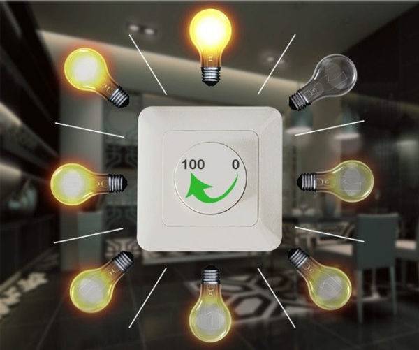
Adjustable light switch
Prices for adjustable switches
Dimmer
The disadvantages of the devices include problems with turning on the lighting when the switch fails. Since one device controls two lamps at once, in the event of a breakdown, both of them will not work.
6 Illuminated two-gang switches: independent connection
Connecting a two-gang switch is just as easy as a single-gang switch. It’s just that not two, but three cores are placed in the socket. One of the cores is a phase, the remaining two are for lamps or chandeliers. That's all the differences.
The phase, as a rule, is most likely to be distinguished in red or brown, and from the chandelier - black or white. Picking up the necessary tool, the “phase” is checked before connecting, after that the wire is marked (you can do anything - electrical tape, varnish, marker).
Having turned off the power, it is time to connect the device to the 220 volt network.
Connecting a switch with two buttons to the mains is slightly different from connecting a single switch, so it's easy to handle.
Knowing that the two-key version of the device has three terminals, one of which is for the phase, and the other two are for the wiring from the lamp, you first need to find a small diagram or the letter L - it indicates the place where the wire for the "phase" is connected.
In the absence of identification marks, the following is done: the phase is connected only to the upper single terminal, the wires from the chandelier must be connected to the lower double terminals.
Three pins for connection. The one at the top is for the phase. Those below are for wires from the chandelier
At the end of the work it is necessary to check the lighting. First press one key, then another. If there are no problems and everything turns on, all that remains is to install it in the socket and assemble it.
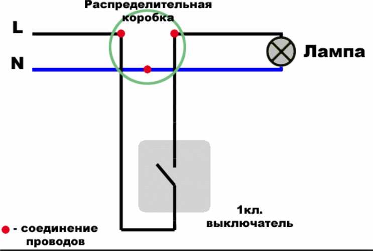
Let's start with a simple one: a diagram for connecting a single-gang switch to a light bulb
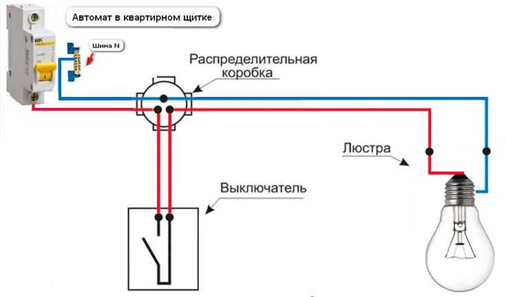
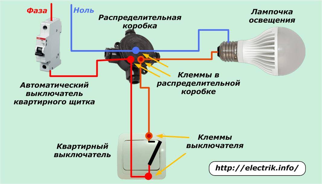
The simplest scheme for connecting a light switch with one key was passed by everyone in a school physics course. In order for the light bulb to light up and turn off, you just need to close and open the electrical circuit. This is what the switch does.


Before starting work, examine the supply wiring to the switch. You can do it the old fashioned way, as experienced electricians do, dividing the wires into “like this” and “your mother”, but it is better to use an indicator screwdriver. When there is contact with the phase line, a red eye lights up on it.
 When you have found the phase, make some kind of mark on the wire so that you do not confuse it with ground or zero in the future
And one more important point in preparation for work. Prepare electrical tape or self-clamping connections in advance.Screw caps are not the best choice; after a few months, such contacts will begin to weaken. Electrical tape is a time-tested material, but not eternal. Self-clamping terminals are a convenient and reliable connection method.
And now we will consider in stages how to connect the light switch correctly.
How does the separate power supply of the chandelier work?
To understand in what sequence to connect the wires in the switch, you need to understand how electricity runs through the chandelier, powering the lamps. In this chapter, we will deal with this issue.
Chandelier structure
No matter how complex the electrical part of the device is, it will always end with conclusions from two, three or four wires. The simplest can only be connected with 2 wires. The number of terminals tells us nothing about their purpose. Let's explore this topic in detail.
Terminal block at the base of the chandelier
In the photo above, you can see a classic terminal block with two colored wires coming out of it.
So, one wire is the working phase, indicated by the Latin letter L (black wire, although it can be any other), and the second is zero - the letter N (blue wires are used for it in all circuits). In fact, the lamp does not care which contact to apply the phase to, it is much more important which of the wires goes to the switch
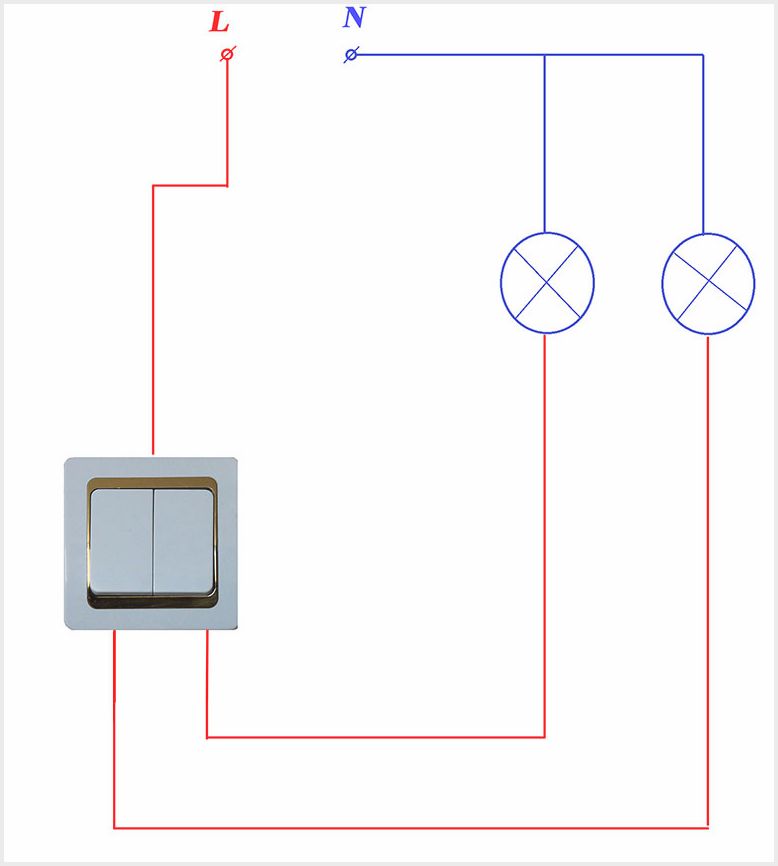
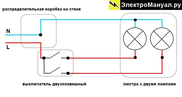
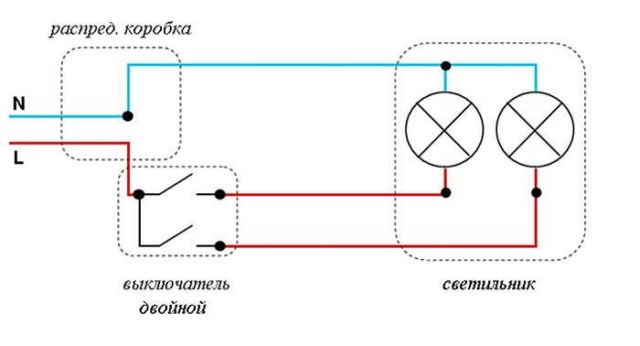
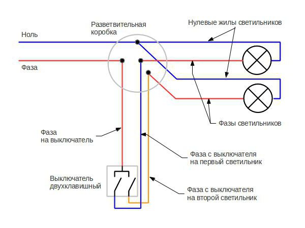
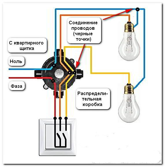
Scheme of connecting fixtures to two-gang switches
Carefully study the presented diagram - we are interested in the gray lines indicating the phase. It immediately becomes clear that they are drawn to the two-gang switch. This is a very important point, since some electricians do not follow this rule and let zero go there.
We return again to our chandelier with two wires. To connect it, you need a single-key switch that will break the phase wire coming from the junction box. At the same time, zero will stretch straight into the box - it does not need a switch, where it will connect to the common zero of the house network. Everything is extremely simple and clear.
Light fixture with 3 wires
The photo shows the base of the sconce, but this does not matter, the principle of operation and connection for other lamps with chandeliers is the same. Here we see that three wires come out of the device case. We already know blue is zero, everything is clear with black, but there was no yellow-green before.
We can connect grounding only if it is provided in the house electrical network. A common ground will be displayed in the junction box, to which yellow-green wires from all electrical points of the house will converge.
In fact, the wiring diagram for such a chandelier is no different from that described earlier, and it requires a single-gang switch.
Chandelier with 6 wires
The photo shows a chandelier with several candles. Since there are two wires from each base, all their leads will stretch to the base of the device, although in good chandeliers the manufacturer makes the entire power circuit himself and often hides it in a hidden part of the case.


Now look how the wires are twisted together - they are connected together by color. In fact, they form the same two wires that we wrote about above. That is, with this connection, you also need only a single-gang switch.
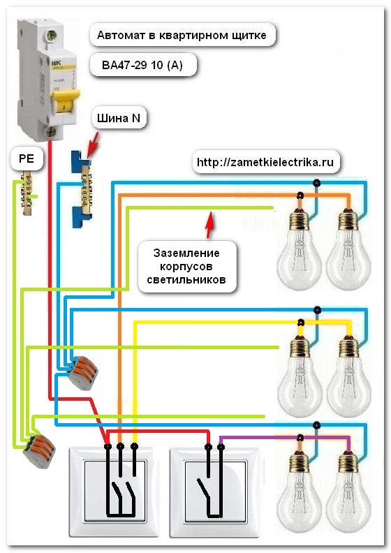
three wire diagram
The last option is when three wires come out of the chandelier, not counting the ground, or you do such a twist yourself - an example of it is shown in the photo above. Let's take a closer look at it. We see that all the neutral wires are connected together and connected to one Vago terminal. Here is a vivid example of how color coding is not respected. The phase wires are separated in a certain order, most likely through one, and connected to two terminals. Such a scheme tells us that two separate phases must be connected to the chandelier to light all the candles. This is exactly what can be done with a two-gang switch.
The final stage - we put the wires in the switch
 The switch is always installed on the phase wire, opening it or distributing it for each phase in the chandelier (when using multi-key switches). Ground wires, if any, are present in the apartment or house electrical wiring, bypass the switch, directly to the chandelier.
As a rule, one-, two- and three-gang switches are on sale. Their connection scheme will be slightly different, so you need to consider three options.
- Connecting a single-gang switch.
This scheme is the simplest and only allows you to turn on and off all the lamps in the chandelier at the same time. It is used in the presence of two lead wires on the ceiling, regardless of the number of wires coming out of the chandelier.
The direct connection of the switch will consist in mounting it on the wall and including the phase wire in the gap. You can determine this wire at the connection point by sequentially touching the input wires with an indicator screwdriver.Upon contact with the phase, the indicator glow will be noticeable on the screwdriver. If the indicator is off, then this means a connection to the neutral wire.
Connection to a two-gang switch.
Here the connection diagram will be complicated by the presence of two phases for two groups of lamps in the chandelier. Therefore, at the water point, the phase is connected to the switch in the manner discussed above. At the output of the switch, there will already be two conclusions. These will be the phases for each of the groups of lamps. They should be connected to the appropriate wires running along the ceiling to the chandelier.
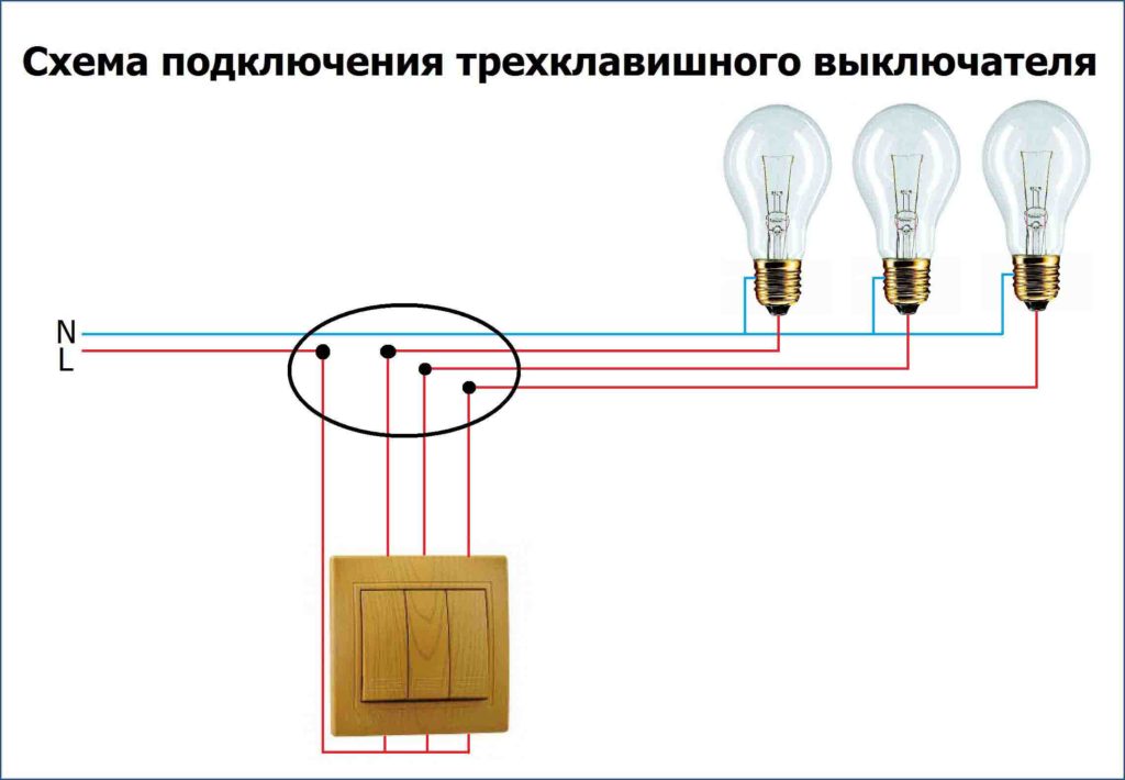
Connecting a chandelier to a three-gang switch.
Such switches are used to control multi-track chandeliers, in which it is possible to distribute the lamps into three independent groups. Accordingly, in the ceiling wiring, one more free core should be provided, if we compare the circuit with the connection of a two-gang switch. The rest of the steps will be similar: a phase is connected to the switch input, and phases are connected to the output for each of the three groups of lamps.
When installing the switch, it is necessary to carefully observe all safety regulations. Otherwise, repairs in the apartment can turn into a tragedy. Therefore, all work on laying wires, mounting switches on walls and connecting wires on the ceiling should be carried out only when the power is turned off. You can make sure that it is turned off with the same indicator screwdriver. At the input point, when it is connected to all of the available wires, the indicator should not light up.
In general, it is quite possible to connect a chandelier on your own even with minimal skills of an electrician. To do this, you should follow only a small list of rules:
- to carry out installation only with the power supply disconnected;
- even before starting to thoroughly study the connection diagram;
- try to use as few extensions and wire connections as possible, preferring solid cables.
The result will be safe and long-term operation of chandeliers with any number of arms in the most comfortable lighting conditions.


