- Expert advice
- How does a protective device function without "ground"?
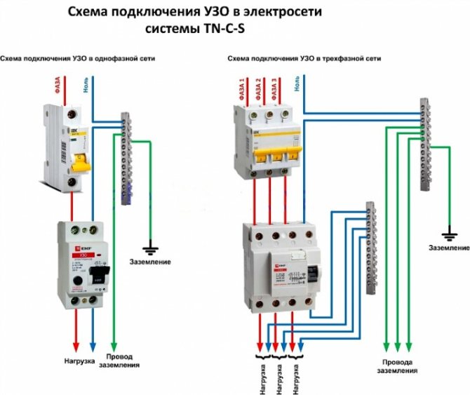
- Connection in the apartment and in a private house
- RCD in the apartment
- RCD in houses on earth
- Where to install?
- The process of installing automation in an electrical panel: step by step instructions
- What problems may arise during the connection
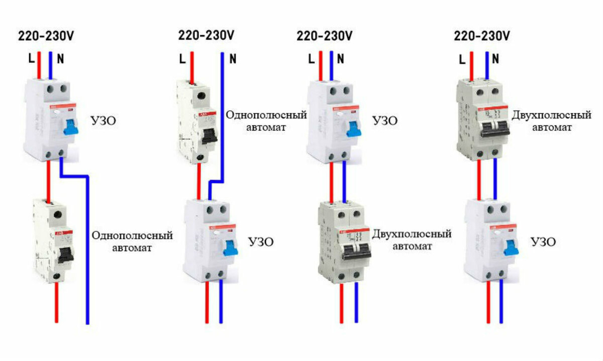
- RCD connection diagrams in a single-phase network
- Without grounding
- Grounded
- RCD selection by parameters
- Rated current
- Breaking current
- Type of monitored leakage current and selectivity
- Installation location
- RCD connection diagrams in a single-phase network
- Without grounding
- Grounded
- The principle of operation of the RCD
- Consider the principle of operation of the RCD in more detail.
- Checking the performance of the RCD
Expert advice
In conclusion, some tips from experts in this field are given that can help with the installation of RCDs:
- For the installation of this equipment in a residential area, it is best to abandon modern electronic models, since their operation depends on the built-in circuit.
- If a wiring diagram is used that does not provide for grounding, it is imperative to add a circuit breaker to it.It will provide protection against voltage overloads and short circuits, while the RCD will monitor the absence of current leakage, thus obtaining a combined protection.
- After the implementation of any circuit or the replacement of one of its elements, it is always necessary to run the protective device to test its performance in order to ensure the correct functioning of the entire system.
- Connecting such a protective device is often a rather difficult task, while this device performs important functions, therefore, if there is the slightest uncertainty in one's own abilities and knowledge, it is recommended to seek help from a professional electrician.
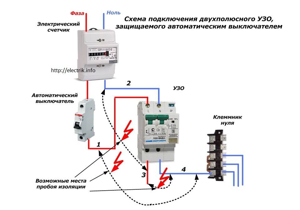
How does a protective device function without "ground"?
The connection option without grounding is a typical case for apartments and private houses of old buildings. The power supply of such buildings, as a rule, is organized without a ground bus. But how correct should we expect the operation of the RCD without turning on the "ground"?
 A wiring option that is widespread in relation to old-style real estate projects. The introduction of residual current devices into the old infrastructure has to be carried out in the absence of an earth bus
For example, during the operation of electrical equipment, a breakdown occurred on the case. In the absence of a ground bus, it is not necessary to count on the instantaneous operation of the installed RCD. If a person touches the body of the broken equipment, the leakage current will flow to the "ground" through the human body.
It will take some period of time (device setting threshold) until the RCD trips.During this period of time (rather short), the risk of injury from the effects of electric current remains quite acceptable. Meanwhile, the RCD would work immediately if there was a ground bus.
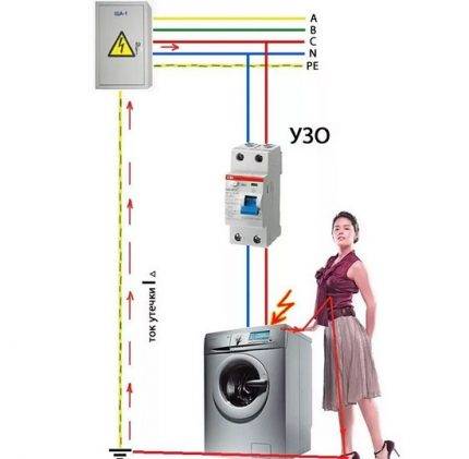 The wiring diagram without the presence of "ground", where the protective device is connected without an additional ground bus, still remains somewhat dangerous for the user. In such situations, you should carefully tune the RCD to the trip threshold
In this example, it is easy to conclude that RCDs and automata in an apartment shield or a private house shield should always be connected together with the connection to the ground bus. Another question is that there are a sufficient number of buildings where it is not possible to do this due to the lack of "land" in the project schemes.
For building options where the power supply is organized without grounding, the switching protection device by means of an RCD actually looks like the only effective means of protection that can be used in such conditions. Therefore, we will consider possible schemes applicable to the power supply of private housing.
Connection in the apartment and in a private house
It is recommended to connect a protection device in an apartment, cottage or country house according to one of the most common schemes:
- TN-C. This is an RCD installation in a network with phase and neutral wires without grounding.
- TN-C-S. It assumes, along with phase and zero, also a grounding PE conductor.
RCD in the apartment
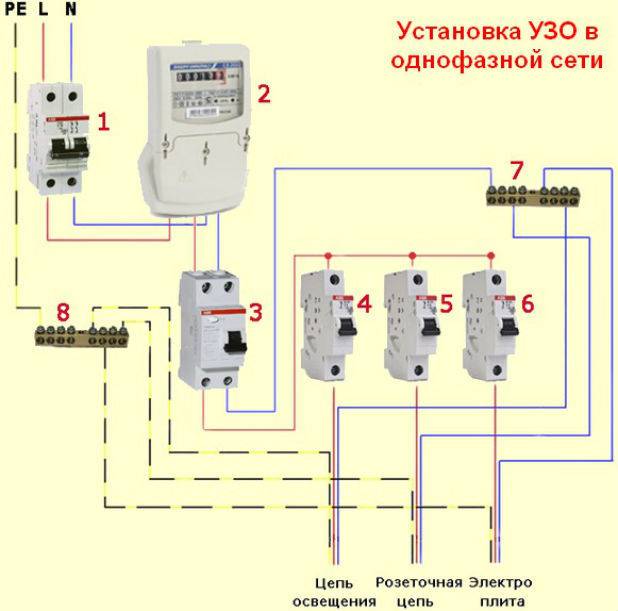
RCD connection in apartments is carried out only according to a single-phase scheme:
- introductory machine;
- electric meter;
- RCD 30 mA;
- electrical wiring throughout the apartment.
For “gluttonous” home devices, such as an electric stove or a washing machine, it is recommended to install additional individual RCDs.
RCD in houses on earth
Particular attention should be paid to protection in a private house and in the country. The connection scheme is as follows:. The connection diagram is as follows:
The connection diagram is as follows:
- introductory machine;
- electric meter;
- RCD from 100 to 300 mA, the choice is made depending on the amount of current consumed by all household appliances;
- RCD for individual current consumption. Typically, 10 to 30 mA is used.
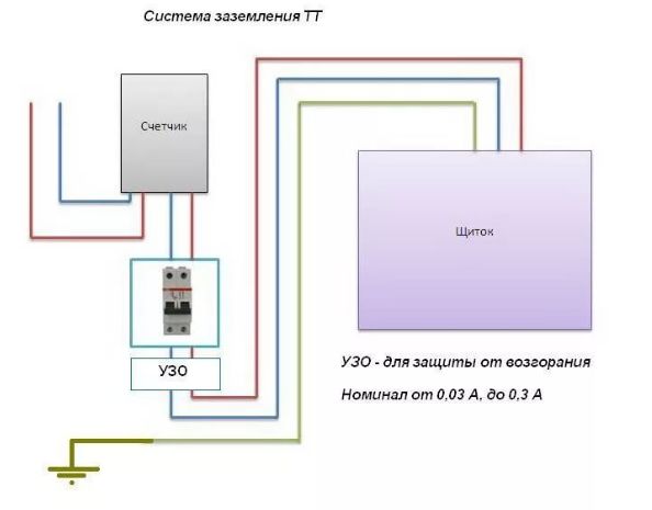
The fact is that, as a rule, houses on the ground have a high degree of energy autonomy and consume more electricity than apartments in high-rise buildings. In this regard, three-phase networks are often used. In addition, in private homes and cottages, it is highly desirable to use the TT grounding system in conjunction with circuit breakers and residual current devices. This is due to the fact that such buildings often use wood - a fire hazardous material, and metal - a good conductor.
Where to install?
As a rule, a protective device is installed in an electrical panel, which is located on the landing or in the apartment of residents. It contains many devices that are responsible for metering and distributing electricity up to a thousand watts. Therefore, in the same shield with the RCD there are automatic machines, an electric meter, clamping blocks and other devices.
If you already have a shield installed, then installing the RCD will be easy. To do this, you need only a minimal set of tools, which includes pliers, wire cutters, screwdrivers and a marker.


The process of installing automation in an electrical panel: step by step instructions
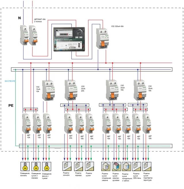
Consider the option of assembling an electrical panel for a one-room apartment, a knife switch, a protective multifunctional device will be used here, then an RCD group will be installed (type “A” for a washing machine and dishwasher, because such a device is recommended by the equipment manufacturer). After the protective device, all groups of automatic switches will go (for air conditioning, refrigerator, washing machine, dishwasher, stove, as well as for lighting). In addition, impulse relays will be used here, they are needed to control lighting fixtures. A special module for electrical wiring will still be installed in the shield, which resembles a junction box.
Step 1: first, you need to place all the automation on the DIN rail, in the way we will connect it.
This is how the devices will be located in the shield
In the panel, first there is a knife switch, then an UZM, four RCDs, a group of circuit breakers of 16 A, 20 A, 32 A. Next, there are 5 pulse relays, 3 lighting groups of 10 A each and a module for connecting wiring.
Step 2: Next, we need a two-pole comb (in order to power the RCD). If the comb is longer than the number of RCDs (in our case, four), then it should be shortened using a special machine.
We cut the comb to the desired size, and then set the limiters along the edges
Step 3: Now for all RCDs, power should be combined by installing a comb. Moreover, the screws of the first RCD should not be tightened.Next, you need to take cable segments of 10 square millimeters, remove the insulation from the ends, crimp with tips, and then connect the knife switch to the UZM, and the UZM to the first UZO.
This is what the connections will look like
Step 4: next, you need to supply power to the circuit breaker, and, accordingly, to the RCD with RCD. This can be done using a power cable that has a plug on one end and two crimped wires with lugs on the other. And first you need to insert the crimped wires into the switch, and only then make a connection to the network.
Next, it remains to connect the plug, then set the approximate range on the USM and press the "Test" button. So, it will turn out to check the performance of the device.
Here you can see that the RCD is functioning, now it is necessary to check each RCD (if connected correctly, it should turn off)
Step 5: now you need to turn off the power and continue the assembly - you should power the group of circuit breakers on the center rail with the comb. Here we will have 3 groups (the first is the hob / oven, the second is the dishwasher and washing machine, the third is the sockets).
We install the comb on the machines and transfer the rails to the shield
Step 6: Next you need to move on to zero tires. Four RCDs are installed here, but only two neutral tires are required, because they are not required for 2 groups. The reason for this is the presence of holes in the machines not only from above, but also from below, so we will connect the load to each of them, respectively, and the bus is not required here.
In this case, a cable of 6 square millimeters is required, which must be measured in place, stripped, clamped the ends and connected to the RCD with its groups.
By the same principle, it is necessary to power the devices with phase cables
Step 7: since we have already connected the automation, it remains to power the impulse relays. Connect them together with a cable of 1.5 square millimeters. In addition, the phase of the machine should be connected to the junction box.
This is what the shield will look like when assembled.
Next, you need to take a marker to put down the labels of the groups for which this or that equipment is intended. This is done in order not to get confused in case of further repairs.
Safety precautions when working with RCD and machine
What problems may arise during the connection
When connecting protection devices, errors can often be encountered that can further damage the network. Therefore, it is advisable to follow a number of guidelines:
- the input terminals of the RCD must be connected only after the corresponding machine, direct connection is not allowed, because the voltage can change dramatically;
- sometimes people confuse zero and phase, so you need to carefully study these values;
- when working with wiring, you must not deviate from the scheme, in particular, this applies to elements with branching, a large number of connected devices and several protection devices for them;
- if there is no grounding conductor in the room, then it is not allowed to replace it with a cable thrown over heating radiators or water pipes, grounding must be carried out in accordance with the instructions;
Principle of operation
when buying devices, it is necessary to study their characteristics and check whether they correspond to the desired network.
You will be interested in generator connection diagram
RCD connection diagrams in a single-phase network
Most household consumers are powered by a single-phase scheme, where one phase and neutral conductor is used for their power supply.
Depending on the individual characteristics of the network, single-phase power supply can be carried out according to the scheme:
- with solidly grounded neutral (TT), in which the fourth wire acts as a return line and is additionally grounded;
- with a combined neutral and protective conductor (TN-C);
- with a separated zero and protective earth (TN-S or TN-C-S, when connecting devices in the room, you will not find differences between these systems).
It should be noted that in the TN-C system, according to the requirements of clause 1.7.80 of the PUE, the use of differential automata is not allowed, except for the protection of individual devices with the obligatory alignment of zero and earth from the device to the RCD. In any situation, when connecting an RCD, the features of the supply network should be taken into account.
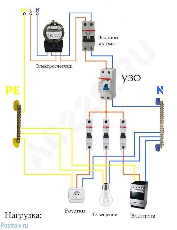
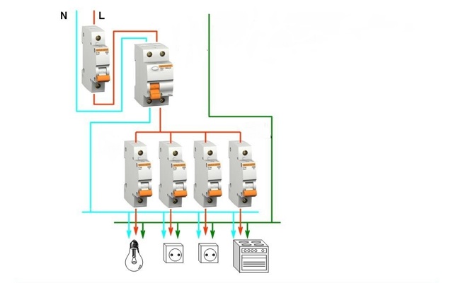
Without grounding
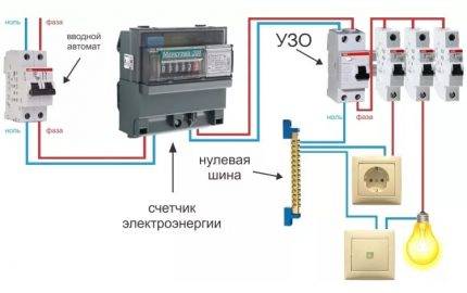
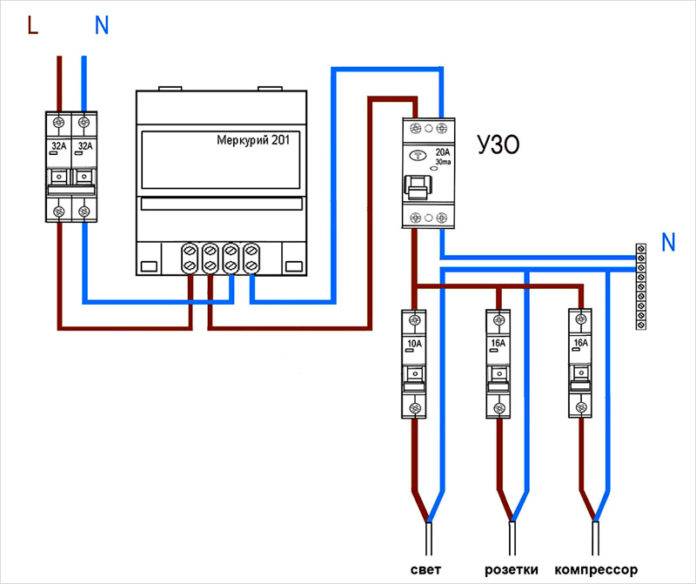
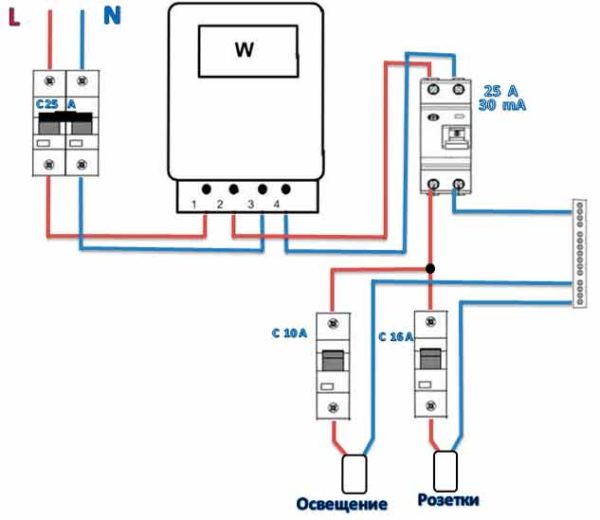
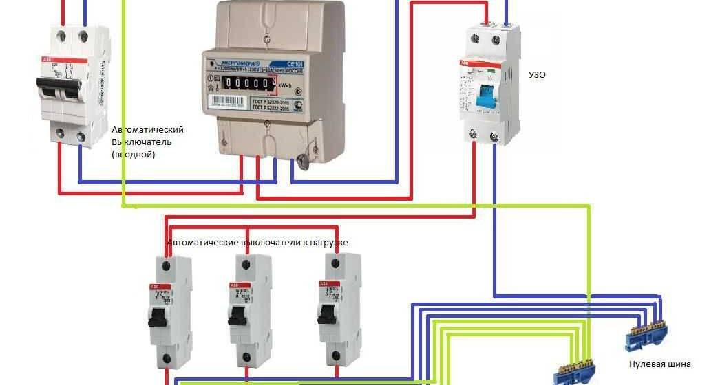
Since not all consumers can boast of having a third wire in their wiring, residents of such premises have to make do with what they have. The simplest scheme for connecting an RCD is to install a protective element after an introductory machine and an electric meter. After the RCD, it is important to connect circuit breakers for various loads with the corresponding tripping current. Note that the principle of operation of the RCD does not provide for the shutdown of current overloads and short circuits, so they must be installed together with circuit breakers.
 Rice. 1: Connecting an RCD in a single-phase two-wire system
This option is relevant for apartments with a small number of connected devices.Since in the event of a short circuit in any of them, turning off will not bring tangible inconvenience, and finding damage will not take much time.
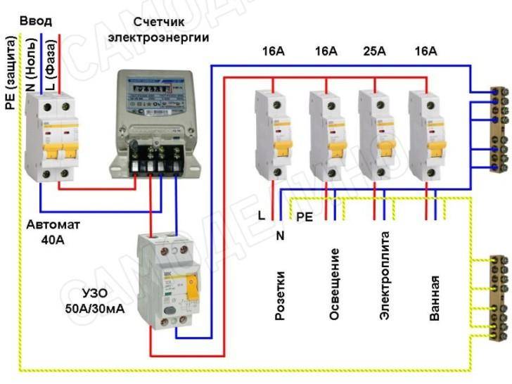
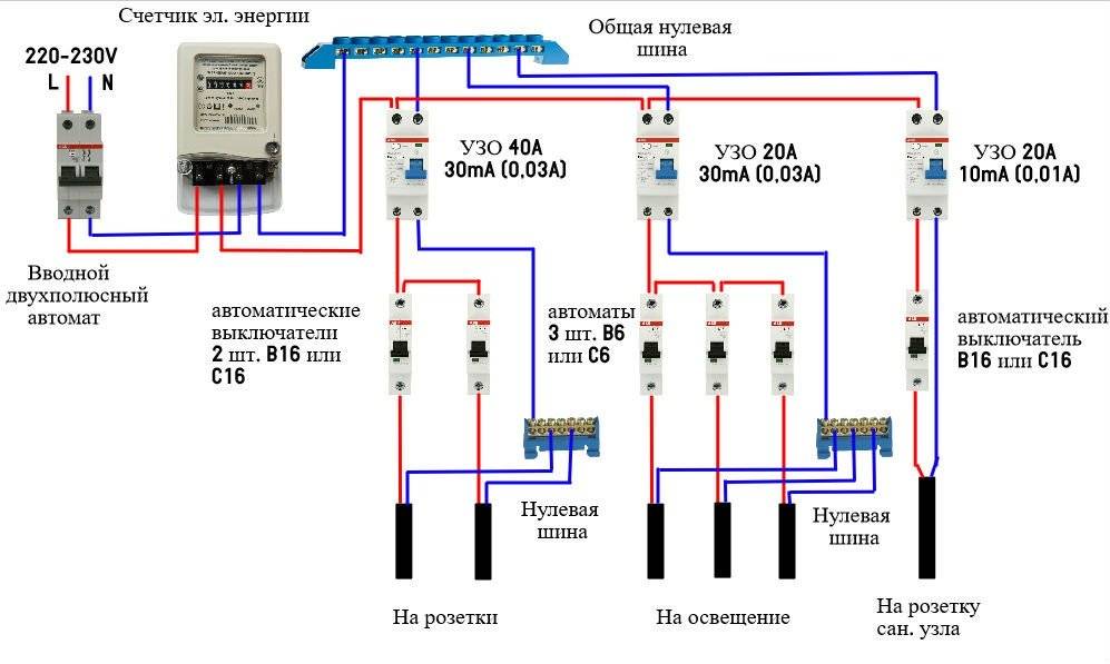
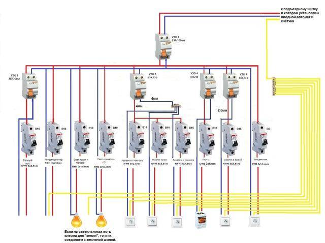
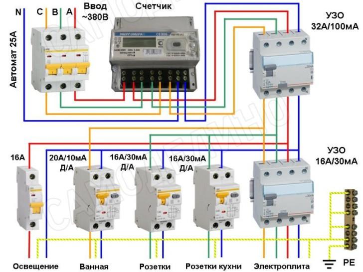
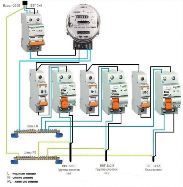
But, in cases where a sufficiently branched power supply circuit is used, several RCDs with different operating currents can be used in it.
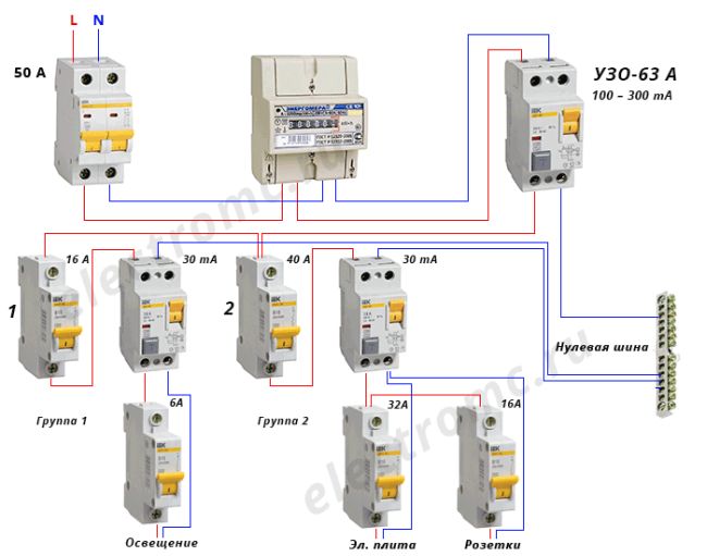
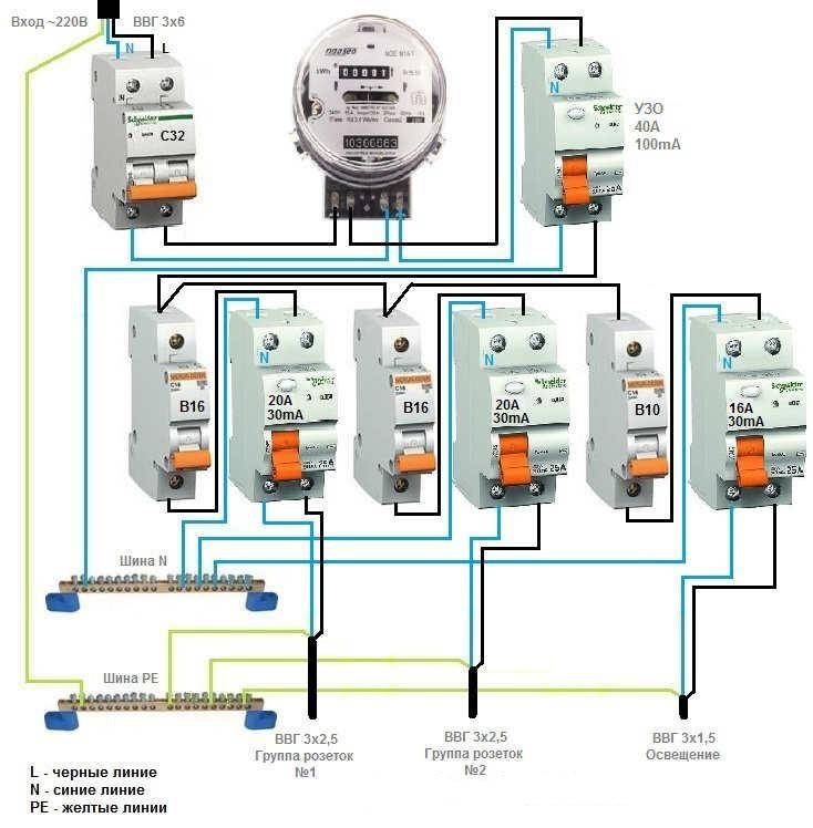
 Rice. 2: RCD connection in a branched single-phase two-wire system
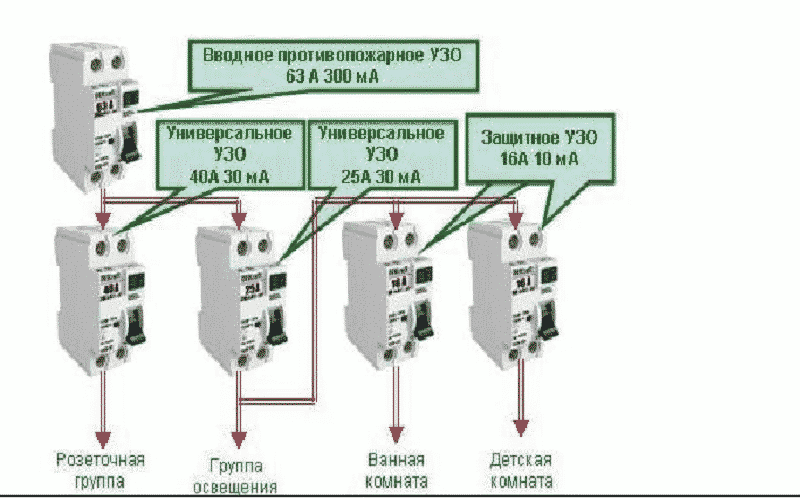
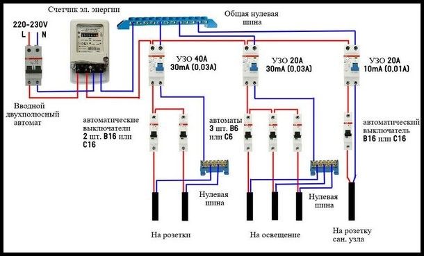
In this connection option, several protective elements are installed, which are selected according to the rated current and the operating current. As a general protection, an introductory fire RCD of 300 mA is connected here, followed by a zero and phase cable to the next 30 mA device, one for sockets, and the second for lighting, a pair of 10 mA units is installed for the bathroom and nursery. The lower the trip rating is used, the more sensitive the protection will be - such RCDs will operate at a much lower leakage current, which is especially true for two-wire circuits. However, it is also not worth installing sensitive automation on all elements, since it has a high percentage of false positives.
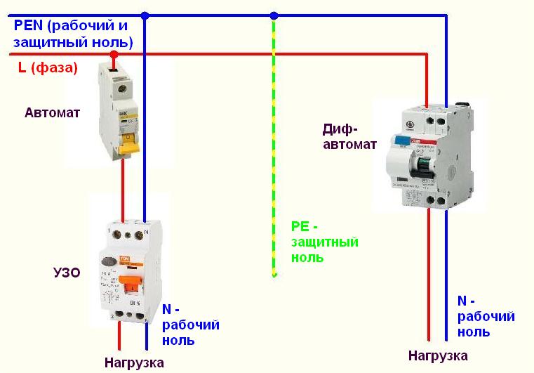
Grounded
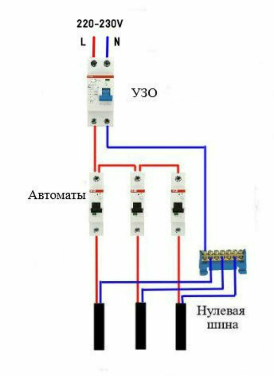
In the presence of a grounding conductor in a single-phase system, the use of an RCD is more appropriate. In such a scheme, connecting the protective wire to the instrument case creates a path for current to leak if the insulation of the wires is broken. Therefore, the protection operation will occur immediately upon damage, and not in the event of a human electric shock.
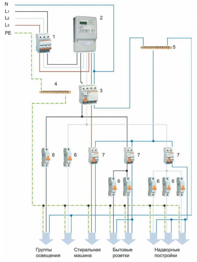
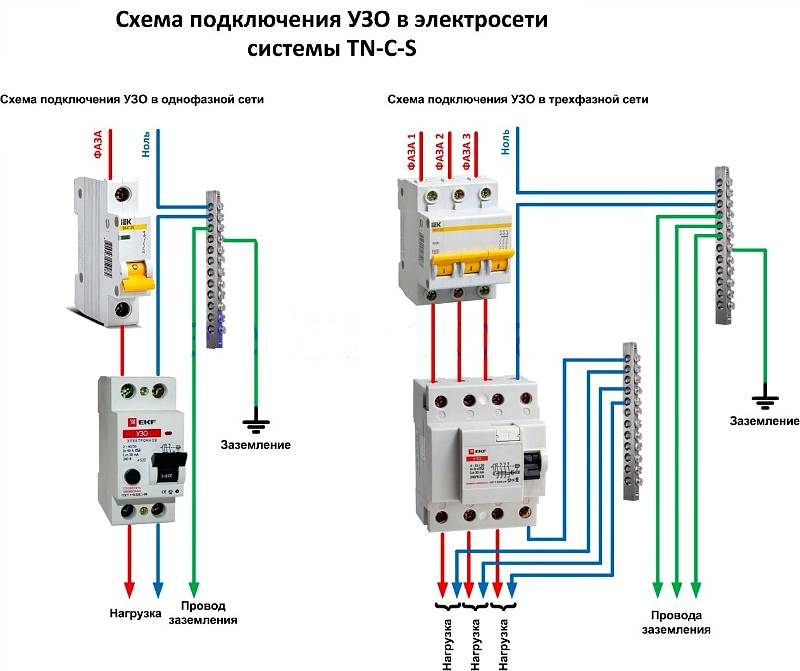
 Rice. 3: Connecting an RCD in a single-phase three-wire system
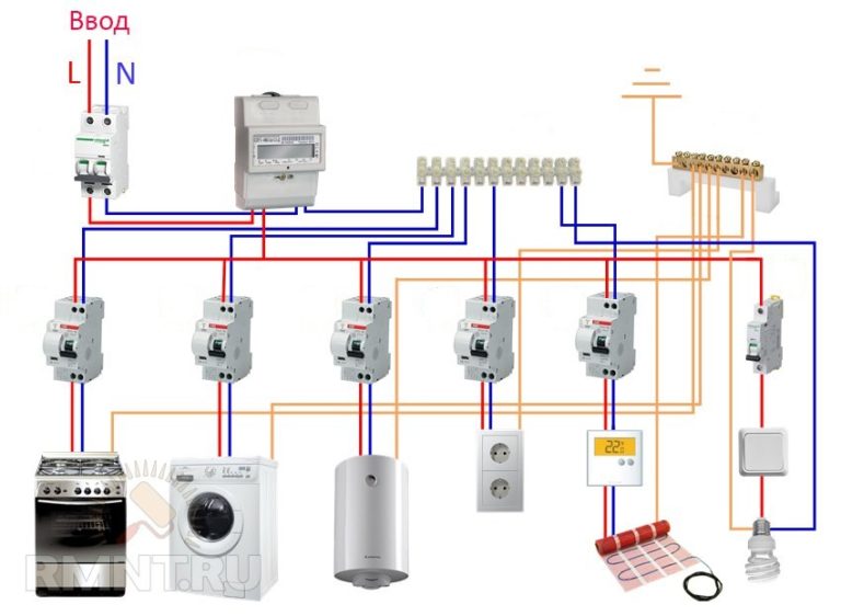
Look at the figure, the connection in a three-wire system is made similarly to a two-wire one, since only a neutral and phase conductor is required for the operation of the device.Grounding is connected only to protected objects through a separate ground bus. Zero can also be connected to a common zero bus, from zero contacts it is wired to the corresponding devices connected to the network.
As in a two-wire single-phase circuit, with a large number of consumers (air conditioner, washing machine, computer, refrigerator and other benefits of civilization), an extremely unpleasant option is the freezing of all of the above electronic circuits with data loss or disruption of their performance. Therefore, for individual devices or entire groups, you can install several RCDs. Of course, their connection will result in additional costs, but it will make finding damage a more convenient procedure.
RCD selection by parameters
After the RCD connection diagram is ready, it is necessary to determine the parameters of the RCD. As you know, it will not save the network from congestion. And short circuit too. These parameters are monitored by the automaton. To ensure the safety of all wiring, an introductory machine is placed at the entrance. After it there is a counter, and then they usually put a fire protection RCD. It is chosen specifically. The leakage current is 100 mA or 300 mA, and the rating is the same as that of the introductory machine or one step higher. That is, if the input machine is at 50 A, the RCD after the counter is set to either 50 A or 63 A.


Fire protection RCD is selected according to the nominal value of the introductory machine
Why a step up? Because the automatic safety switches are triggered with a delay. The current exceeding the nominal by no more than 25%, they can pass at least an hour.The RCD is not designed for long-term exposure to increased currents, and with a high probability it will burn out. The house will be left without electricity. But this concerns the determination of the value of the fire RCD. Others are chosen differently.
Rated current
How to choose the value of the RCD? It is selected according to the method for determining the nominal value of the machine - depending on the cross-section of the wire on which the device is installed. The rated current of the protective device cannot be greater than the maximum allowable current for a given wire. For ease of selection, there are special tables, one of them is below.
Table for selecting the rating of the circuit breaker and RCD
In the leftmost column we find the cross section of the wire, to the right there is the recommended rating of the circuit breaker. The same should be with the RCD. So it is not difficult to choose the value of the protective device against leakage current.
Breaking current
When determining this parameter, you will also need an RCD connection diagram. The rated breaking current of the RCD is the value of the leakage current at which the power is turned off on the protected line. This setting can be 6mA, 10mA, 30mA, 100mA, 500mA. The smallest current - 6 mA - is used in the USA, in European countries, and we don’t have them on sale either. Devices with a maximum leakage current of 100 mA or more are used as fire protection. They stand in front of the entrance machine.
For all other RCDs, this parameter is selected according to simple rules:
- Protection devices with a rated tripping current of 10 mA are installed on lines that go to rooms with high humidity. In a house and apartment, this is a bathroom; there may also be lighting or sockets in a bathhouse, pool, etc. The same tripping current is set if the line feeds one electrical appliance.For example, a washing machine, electric stove, etc. But if there are sockets in the same line, more leakage current is needed.
- An RCD with a leakage current of 30 mA is placed on group power lines. When more than one device is connected.
This is a simple algorithm based on experience. There is another method that takes into account not only the number of consumers, but also the rated current in the protection zone, or rather, the cross section of the wire, since the rated current of the power line depends on this parameter. This is more correct, as it explains how to choose the amount of leakage current for a general RCD, for example, and not just for devices that are put on consumers.
Table for selection of rated tripping current for RCD
It is also necessary to take into account the individual leakage currents of each of the devices. The fact is that on every more or less complex device, some small current “leaks”. Responsible manufacturers indicate it in the specifications. Suppose there is only one device on the line, but its own leakage current is more than 10 mA, an RCD with a leakage current of 30 mA is installed.
Type of monitored leakage current and selectivity
Different devices and devices use different forms of current, respectively, the RCD must control leakage currents of a different nature.
- AC - alternating current is monitored (sinusoidal form);
- A - variable + pulsating (pulses);
- B - constant, impulse, smoothed variable, variable;
- Selectivity. S and G - with a shutdown time delay (to exclude accidental trips), the G-type has a shorter shutter speed.
Selecting the type of leakage current to be monitored
RCD is selected depending on the type of protected load. If digital equipment is to be connected to the line, either type A is required. Lighting on the line is AC.Type B, of course, is good, but too expensive. It is usually placed in rooms with increased danger in production, and very rarely in the private sector or in apartments.
RCDs of class G and S are installed in complex circuits if there are RCDs of several levels. This class is chosen for the "highest" level, then when one of the "lower" ones is triggered, the input protective device will not turn off the power.
Installation location
Usually, the installation location of the RCD in the electrical panel. It contains various devices for accounting and distribution of electrical energy up to 1000 V. In the electrical panel, along with the RCD, automatic switches, an electric meter, distribution terminal blocks, and other electrical appliances are installed. If you have an electrical panel installed, then you will need a minimum set of electricians to install a residual current device. It will include pliers, side cutters, a set of screwdrivers, a marker.


In rare cases, a set of socket wrenches and an electrical tester may be required. The RCD is mounted on a DIN block. If there is no space on the existing block, then you will need to install an additional one.
RCD connection diagrams in a single-phase network
Most household consumers are powered by a single-phase scheme, where one phase and neutral conductor is used for their power supply.
Depending on the individual characteristics of the network, single-phase power supply can be carried out according to the scheme:
- with solidly grounded neutral (TT), in which the fourth wire acts as a return line and is additionally grounded;
- with a combined neutral and protective conductor (TN-C);
- with a separated zero and protective earth (TN-S or TN-C-S, when connecting devices in the room, you will not find differences between these systems).
It should be noted that in the TN-C system, according to the requirements of clause 1.7.80 of the PUE, the use of differential automata is not allowed, except for the protection of individual devices with the obligatory alignment of zero and earth from the device to the RCD. In any situation, when connecting an RCD, the features of the supply network should be taken into account.
Without grounding
Since not all consumers can boast of having a third wire in their wiring, residents of such premises have to make do with what they have. The simplest scheme for connecting an RCD is to install a protective element after an introductory machine and an electric meter. After the RCD, it is important to connect circuit breakers for various loads with the corresponding tripping current. Note that the principle of operation of the RCD does not provide for the shutdown of current overloads and short circuits, so they must be installed together with circuit breakers.
Rice. 1: Connecting an RCD in a single-phase two-wire system
This option is relevant for apartments with a small number of connected devices. Since in the event of a short circuit in any of them, turning off will not bring tangible inconvenience, and finding damage will not take much time.
But, in cases where a sufficiently branched power supply circuit is used, several RCDs with different operating currents can be used in it.
Rice. 2: RCD connection in a branched single-phase two-wire system
In this connection option, several protective elements are installed, which are selected according to the rated current and the operating current.As a general protection, an introductory fire RCD of 300 mA is connected here, followed by a zero and phase cable to the next 30 mA device, one for sockets, and the second for lighting, a pair of 10 mA units is installed for the bathroom and nursery. The lower the trip rating is used, the more sensitive the protection will be - such RCDs will operate at a much lower leakage current, which is especially true for two-wire circuits. However, it is also not worth installing sensitive automation on all elements, since it has a high percentage of false positives.
Grounded
In the presence of a grounding conductor in a single-phase system, the use of an RCD is more appropriate. In such a scheme, connecting the protective wire to the instrument case creates a path for current to leak if the insulation of the wires is broken. Therefore, the protection operation will occur immediately upon damage, and not in the event of a human electric shock.
Rice. 3: Connecting an RCD in a single-phase three-wire system
Look at the figure, the connection in a three-wire system is made similarly to a two-wire one, since only a neutral and phase conductor is required for the operation of the device. Grounding is connected only to protected objects through a separate ground bus. Zero can also be connected to a common zero bus, from zero contacts it is wired to the corresponding devices connected to the network.
As in a two-wire single-phase circuit, with a large number of consumers (air conditioner, washing machine, computer, refrigerator and other benefits of civilization), an extremely unpleasant option is the freezing of all of the above electronic circuits with data loss or disruption of their performance.Therefore, for individual devices or entire groups, you can install several RCDs. Of course, their connection will result in additional costs, but it will make finding damage a more convenient procedure.
The principle of operation of the RCD
The principle of operation of the RCD. - this question is asked by many.
As is known from the course of electrical engineering, electric current flows from the network through the phase wire through the load and returns back to the network through the neutral wire. This pattern formed the basis of the work of the RCD.
The principle of operation of the residual current device is based on comparing the magnitude of the current at the input and output of the protected object.
If these currents are equal, Iin = Iexit RCD does not respond. If Iin > Iexit The RCD senses a leak and trips.
That is, the currents flowing through the phase and neutral wires must be equal (this applies to a single-phase two-wire network, for a three-phase four-wire network, the current in the neutral is equal to the sum of the currents that flow in the phases). If the currents are not equal, then there is a leak, to which the RCD reacts.


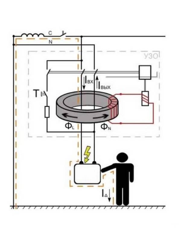
Consider the principle of operation of the RCD in more detail.
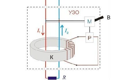
The main structural element of the residual current device is a differential current transformer. This is a toroidal core on which windings are wound.
During normal operation of the network, the electric current flowing in the phase and neutral wires creates alternating magnetic fluxes in these windings, which are equal in magnitude but opposite in direction. The resulting magnetic flux in the toroidal core will be equal to:
As can be seen from the formula, the magnetic flux in the toroidal core of the RCD will be equal to zero, therefore, there will be no EMF in the control winding, the current in it, respectively, too.The residual current device in this case does not work and is in sleep mode.
Now let's imagine that a person touched an electrical appliance, which, as a result of insulation damage, turned out to be under phase voltage. Now, in addition to the load current, an additional current will flow through the RCD - the leakage current.
In this case, the currents in the phase and neutral wires will not be equal. The resulting magnetic flux will also not be zero:
Under the influence of the resulting magnetic flux, an EMF is excited in the control winding, and under the action of the EMF, a current arises in it. The current that has arisen in the control winding activates the magnetoelectric relay, which disconnects the power contacts.
The maximum current in the control winding will appear when there is no current in one of the power windings. That is, this is a situation when a person touches a phase wire, for example, in a socket in this case, the current in the neutral wire will not flow.
Despite the fact that the leakage current is very small, RCDs are equipped with magnetoelectric relays with high sensitivity, the threshold element of which is able to respond to a leakage current of 10 mA.
Leakage current is one of the main parameters by which an RCD is selected. There is a scale of rated differential trip currents 10 mA, 30 mA, 100 mA, 300 mA, 500 mA.
It should be understood that the residual current device responds only to leakage currents and does not work with overloads and short circuits. The RCD will not work even if a person simultaneously grasps the phase and neutral wires. This is due to the fact that the human body in this case can be represented as a load through which an electric current passes.
Because of this, instead of the RCD, differential automata are installed, which, by their design, combine both the RCD and the circuit breaker.
Checking the performance of the RCD
In order to monitor the health (operability) of the RCD, a “Test” button is provided on its body. when pressed, a leakage current is artificially created (differential current). If the residual current device is working properly, then when you press the "Test" button, it will turn off.
Experts recommend that such control be carried out approximately once a month.
Related content on the site:


