- Helpful Tips
- What is needed to connect a three-phase 220 V motor
- Installation of additional equipment
- The device and features of the float
- Selecting the right unit
- How to connect a circulation pump to electricity - Construction and repair
- Connection methods
- What is a circulation pump and why is it needed
- Preparing to connect
- Connecting an electric motor: where to start
- Connecting a borehole pump to power supply with a control unit (automation unit)
- What is important to know?
- Further switching: we work with a working magnetic starter
- Why ELM327 won't connect to ECU?
- For which vehicles is the ELM327 suitable?
- Breakdowns and repair of the float switch
- carbureted engine
- Features of equipment installation
- Before the first start.
- Ways to automate water wells
- Connecting a borehole pump without auxiliary equipment
- Let's summarize the work done
Helpful Tips
Sometimes an electric motor from an old automatic washing machine cannot be started, and the reasons for this are both mechanical and electrical.
The reasons for the difficulties of starting an electric motor can manifest themselves as follows.
- When turned on, the motor heats up, but the shaft does not rotate.If you try to rotate the shaft by hand, you can hear the rattle of metal parts. This sound indicates that the bearing mechanism of the electric motor is damaged and needs to be removed and replaced.
- Sometimes the rotation of the electric motor shaft can be difficult if any foreign objects have accumulated in the gap between the stator and the rotor, which must be removed and the start should be tried again.
- Ringing the entire electrical circuit with a multimeter will help identify the presence of a break. For commutator-type electric motors, the starting problem may be that the brushes are worn out, as a result of which they cannot tightly adjoin the commutator and no energy is generated.
Sometimes, when starting an electric motor from modern models of washing machines, they try to determine the starting winding, but new generations of electric motors do not have it, and such a motor is started without using a capacitor.
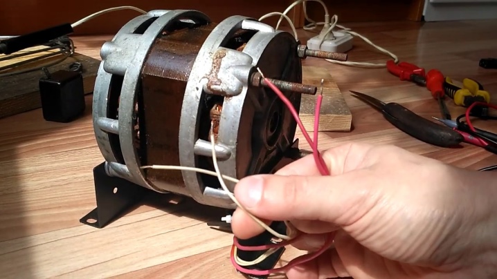
You can find out about a simple way to connect a washing machine motor without appliances below.
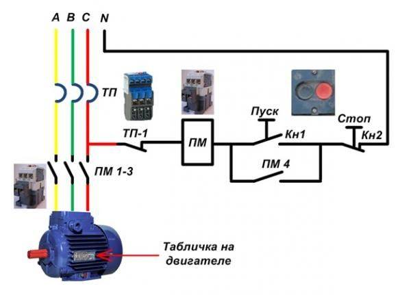
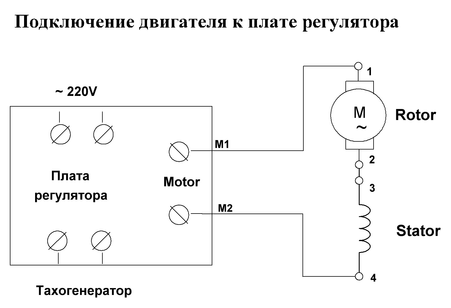
What is needed to connect a three-phase 220 V motor
Interestingly, in the presence of many different magnetic starters that I found in the garage, an unexpected problem was discovered. It consisted in the absence of normal start buttons - only fairly old samples were at hand. But first things first.
For work you will need:
- The electric motor itself.
- Two capacitors (starting and working).
- Magnetic starter of the appropriate rating.
- A second starter to supply power to one of the capacitors (if there was a newer push-button post with two constantly open contacts, it would not be needed).
- Wires of the appropriate section.
- Button post for 2 control points.
- Pliers, screwdrivers, wrenches.
Having prepared everything you need, let's get to work.
Installation of additional equipment
Regardless of the type of heating circuit used, where one boiler serves as a heat producer, it will be enough to install a single pumping device.
If the system is structurally more complex, it is possible to use additional devices that provide forced circulation of the liquid.
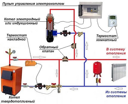
An example of a joint piping scheme for a solid fuel boiler paired with an electric one. This heating system has two pumping devices
The need for this appears in the following cases:
- when heating a house, more than one boiler unit is involved;
- if there is a buffer capacity in the strapping scheme;
- the heating system diverges into several branches, for example, maintenance of an indirect boiler, several floors, etc.;
- when using a hydraulic separator;
- when the length of the pipeline is more than 80 meters;
- when organizing the movement of water in the floor heating circuits.
To perform the correct piping of several boilers operating on different fuels, it is necessary to install backup pumps.
For a circuit with a heat accumulator, it is also necessary to install an additional circulation pump. In this case, the line consists of two circuits - heating and boiler.
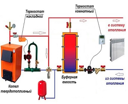
The buffer tank separates the system into two circuits, although in practice there may be more.
A more complex heating scheme is implemented in large houses on 2-3 floors. Due to the branching of the system into several lines, pumps for pumping coolant are used from 2 or more. They are responsible for supplying the coolant to each of the floors to various heating devices.
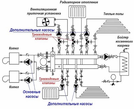
Regardless of the number of pumping devices, they are installed on the bypass. In the off-season, the heating system can work without a pump, which is closed using ball valves
If it is planned to organize heated floors in the house, then it is advisable to install two circulation pumps. In the complex, the pumping and mixing unit is responsible for the preparation of the coolant, i.e. keeping the temperature at 30-40 ° C.
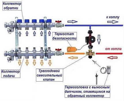
So that the power of the main pumping device is enough to overcome local hydraulic resistance contours of the floor, the length of the line should not exceed 50 m. Otherwise, the heating of the floors will become uneven, respectively, and the premises
In some cases, the installation of pumping units is not required at all. Many models of wall-mounted electric and gas generators already have built-in circulation devices.


The device and features of the float
The floats on the market have almost the same design. They consist of:
- factory switch;
- lever for connecting switch contacts;
- metal ball;
- three wires placed in a cable.
The internal parts of the float are protected by a sealed plastic case. It prevents electrical wiring from coming into contact with water.
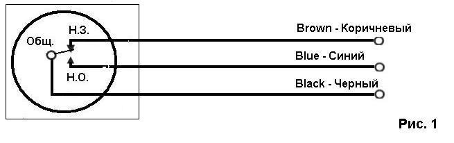
Each float for the pump is equipped with three wires. The first is connected to a regular open contact, and the second to a closed one. The third wire remains common to all.
Sometimes on the market you can find a pump with a float equipped with two thin wires. When the pump is turned off, they break the electrical circuit and reconnect it when the user turns on the pumping equipment.
A float with three wires is universal.It is suitable not only for monitoring dry running, but also for shutting down the unit in case of overflow. Switching modes in it occurs between two connected and one common wires.
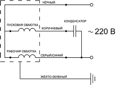
The float pump can be equipped with wires of different colors. As a rule, the black wire is common. Thanks to the blue wire, the equipment is turned off if the water level reaches a critical level. The brown wire is responsible for pump regulation if the unit is used to fill a tank.
You can prevent accidental overflow or equipment from going dry by adjusting the wires inside the float. In this case, it should be borne in mind that the pump should be turned off when it is still under the water column.
The steel ball is responsible for the position of the float. A lever built into the design is required to switch contacts that turn equipment on and off.
Magnets help to fix the ball in the desired position. In this case, the inclination that allows the ball to move freely is 70°. This parameter may vary depending on the modification of the equipment.
Selecting the right unit
When choosing a pump, attention is paid to two main parameters: the force of the coolant flow and the hydraulic resistance that it overcomes when creating pressure. At the same time, the characteristics of the purchased circulation pump should be 10-15% lower than the calculated values. If you install a powerful pump in the heating system, you may encounter the problem of increasing power consumption, excessive noise, and rapid wear of equipment parts.
A low-power pump will not be able to provide the pumping of the coolant in the required volume.Many models of modern circulation pumps are equipped with electronic or manual motor shaft speed controllers. The highest efficiency value is achieved at maximum shaft speed
If you install a powerful pump in the heating system, you may encounter the problem of increasing power consumption, excessive noise, and rapid wear of equipment parts. A low-power pump will not be able to provide the pumping of the coolant in the required volume. Many models of modern circulation pumps are equipped with electronic or manual motor shaft speed controllers. The highest efficiency value is achieved at maximum shaft speed.
Thermal valves, installed in many heating systems, regulate the temperature in the room in accordance with the set parameters. The valve closes when the temperature rises. This increases the hydraulic resistance and, accordingly, increases the pressure. These processes are accompanied by the appearance of noise, which can be eliminated by switching the pump to low speeds. Pumps with built-in electronics that can smoothly regulate pressure drops depending on changes in the amount of water cope with this task more efficiently.
How to connect a circulation pump to electricity - Construction and repair

The circulation pump is an important element of modern heating systems. It is needed for forced circulation of water in the heating system, which allows you to save up to 30% on heating private houses and cottages.
The savings lies in the fact that the coolant quickly passes through the pipes, as a result of which the water does not cool down so quickly and, accordingly, there is no need to heat it up much. This article will discuss the correct connection of the circulation pump to the mains.
Diagrams and video instructions will help you to carry out wiring without errors!
Connection methods
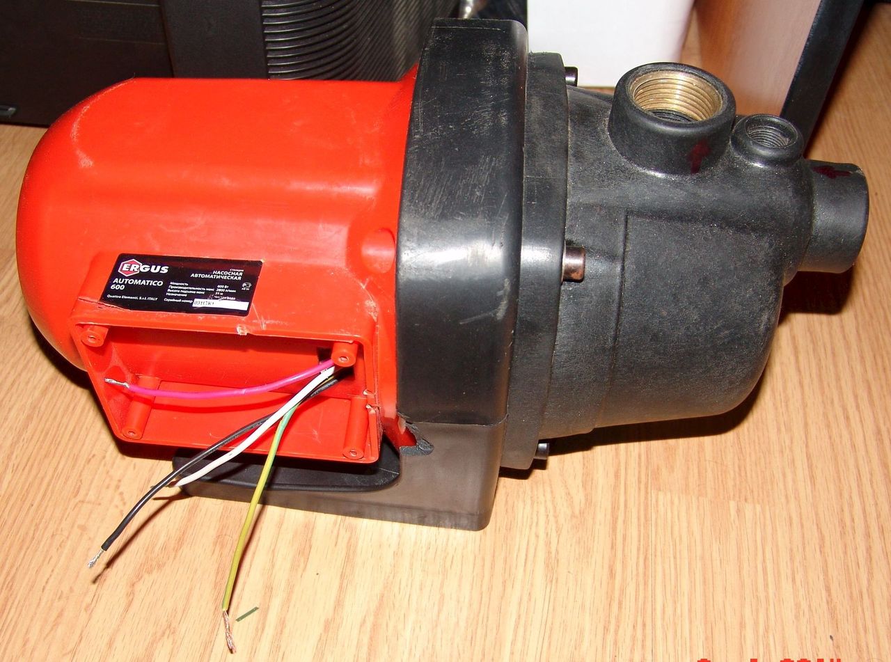
Connection to the mains using a plug and socket. This method involves installing an electrical outlet in close proximity to the place where the circulation pump is mounted. Sometimes they can be supplied with a cable connected and a plug included, as in the photo:
In this case, you can simply plug the device into the mains using the socket located within the reach of the cable. You just need to make sure that there is a third, grounding contact in the outlet.
In the absence of a cord with a plug, they must be purchased in addition, or removed from an unused electrical appliance
You should pay attention to the cross-section of the conductors of the cord. It should be in the range from 1.5 mm 2 to 2.5 mm 2
The wires must be stranded copper, providing resistance to repeated bending. A cord with a plug for connecting electrical appliances to the network is shown in the photo below:
Before connecting the circulation pump, it is necessary to find out which of the three wires of the cord is connected to the grounding contact of the plug. This can be done with an ohmmeter, at the same time checking the integrity of the remaining wires.


![The network cable is not properly connected or may be damaged [Solved]](https://fix.housecope.com/wp-content/uploads/a/1/9/a1934d49429207ce4d7d7df629243aaa.jpeg)
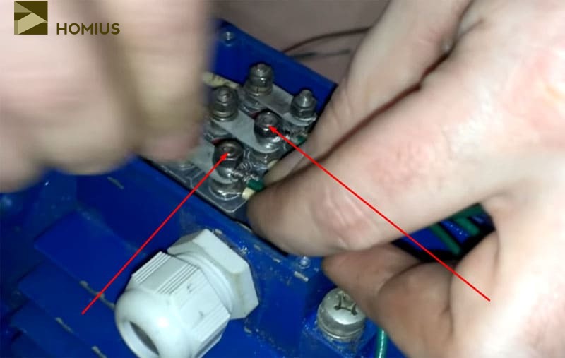
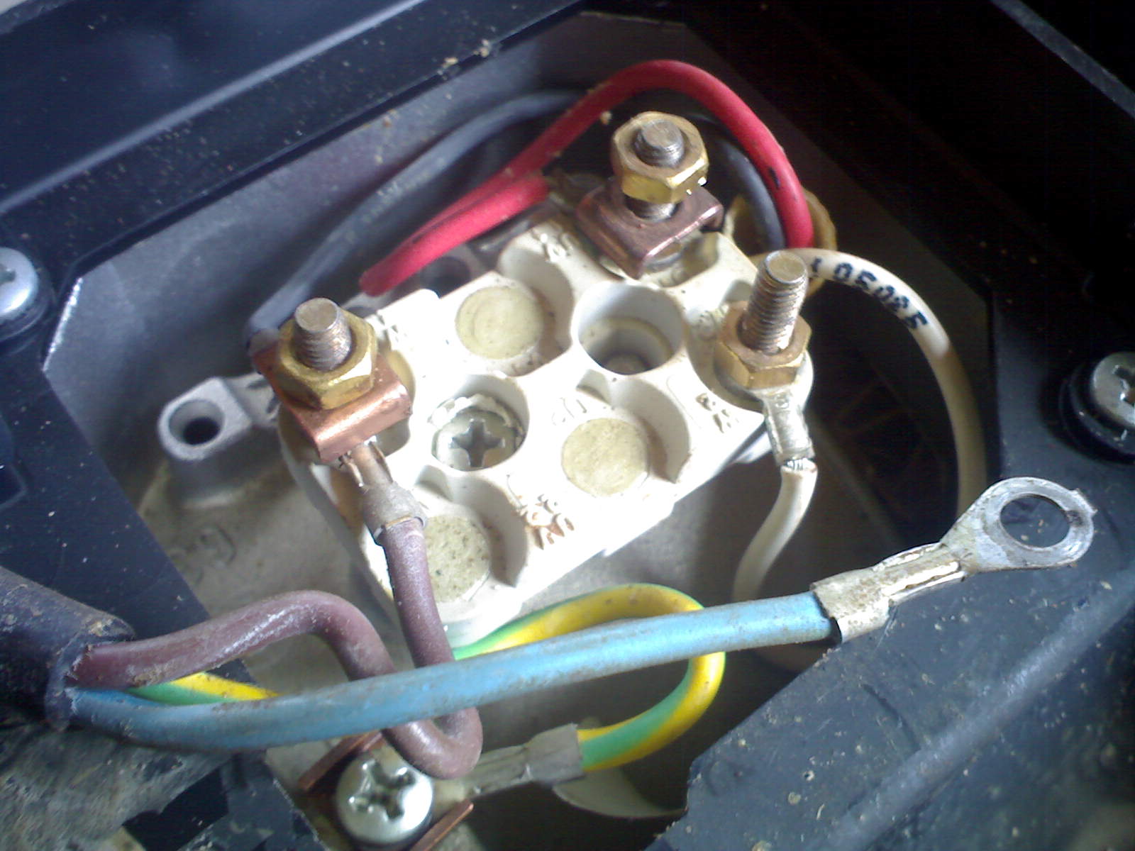
We unscrew the clamp of the cable sleeve (in the first photo it is a plastic nut into which the cable is inserted), we put it on our cord, we put the cord into the sleeve. If there is a cable tie inside the box, we pass the cord through it.We connect the ends of the cord wires, previously stripped of insulation, to the terminals.
To the terminals L and N you need to connect the wires connected to the plugs of the plug (do not be afraid to mix them up, this is not critical), to the terminal PE you should connect the wire of the ground contact of the plug (but you can’t make a mistake here).
The instruction attached to the product prohibits its operation without protective grounding. Next, tighten the clamp (if any), tighten the clamp of the cable gland tightly, bury terminal box cover.
The pump is ready to be connected to the mains.
Fixed connection. The connection diagram of the circulation pump to the mains with grounding is provided below:
The requirements for the wire cross section are the same as in the previous version. The cable for this installation can be used both flexible and inflexible, copper, brand VVG. or aluminum, AVVG. If the cable is inflexible, the installation must ensure its immobility. To do this, the cable along the entire route is fixed with clamps.
In this embodiment, a residual current device (differential circuit breaker) is used. Instead, you can use a conventional single-pole machine, passing only the phase wire through it.
If the machine is installed in a panel where there is a PE bus, then the cable from the pump to the machine must be three-core. In the absence of such a bus, the PE terminal should be connected to a grounding device.
Such a connection can be made with a separate wire.
Separately, I would like to consider such an installation option as connecting the pump to the UPS. It is most preferable and ensures the independence of the functioning of the heating system from interruptions in the supply of electricity. Scheme of connecting the circulation pump to uninterruptible power supply provided below:
The power of the UPS should be selected based on the power of the pump motor.
The battery capacity is determined by the estimated autonomous power supply time of the circulation pump, that is, the time when the power supply is turned off.
Finally, we recommend watching video instructions for connecting various models of pumps to the electrical network:
Scheme for connecting the circulation pump to the thermostat
So we examined how the circulation pump is connected to the mains correctly. The diagram and video examples helped to consolidate the material and clearly see the nuances of the installation!
It will be useful to read:
Scheme for connecting the circulation pump to the thermostat
What is a circulation pump and why is it needed
A circulation pump is a device that changes the speed of movement of a liquid medium without changing the pressure. In heating systems, it is placed for more efficient heating. In systems with forced circulation, it is an indispensable element, in gravitational systems it can be set if it is necessary to increase the thermal power. Installing a circulation pump with several speeds makes it possible to change the amount of heat transferred depending on the temperature outside, thus maintaining a stable temperature in the room.
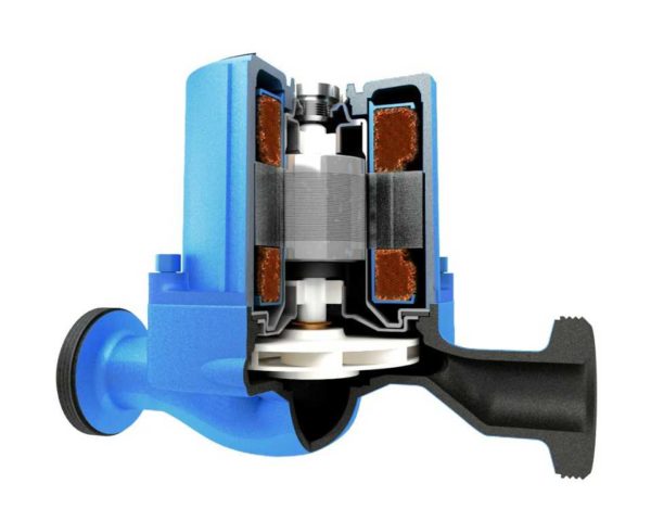
Glandless circulation pump cutaway
There are two types of such units - with a dry and wet rotor. Devices with a dry rotor have a high efficiency (about 80%), but they are very noisy and require regular maintenance. Wet rotor units operate almost silently, with normal coolant quality, they can pump water without failures for more than 10 years.They have a lower efficiency (about 50%), but their characteristics are more than enough to heat any private house.


Preparing to connect
Before connecting, you must make sure that the converter model corresponds to the design one, and all the characteristics of the frequency controller match the parameters of the electric motor. Also, the voltage in the supply network should not be lower or higher than the rated voltage of the frequency converter. Next, choose a place to place the converter. It must satisfy the following conditions:
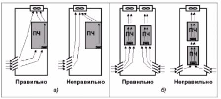
- The class of protection of the housing against moisture and dust must correspond to the location of the frequency controller. Most of the devices are IP20 rated and designed for installation in rooms with low humidity, ventilated electrical cabinets, in drive control panels. Chastotniki IP54 and IP65 can be installed in open areas near the motors. This rule also applies to external control panels, which are equipped with frequency converters from many manufacturers.
- When mounting in cabinets, it is required to provide the necessary distance from the walls and between other frequency converters and automation devices that heat up during operation. The distance depends on the power of electrical devices. The power of the fans must correspond to the number of frequency converters and other electrical devices and devices placed in one cabinet in order to ensure sufficient heat dissipation.
- The frequency regulator is installed at a sufficient distance from sources of a powerful electromagnetic field, strong vibrations. If this condition cannot be met, the devices are installed in shielding cabinets on vibration-damping supports.The device is mounted on a flat surface made of non-combustible material, in a place where exposure to direct sunlight is excluded.
- The climatic version of the frequency converter must also correspond to the temperature range, altitude, humidity and other operating conditions.
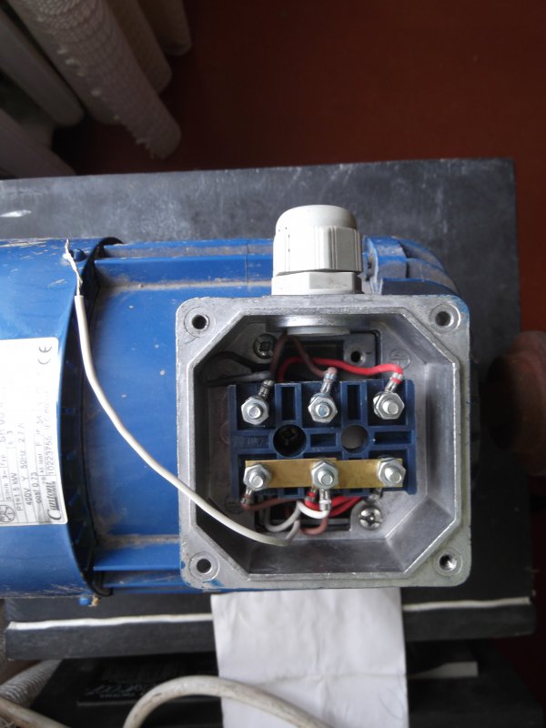
Connecting an electric motor: where to start
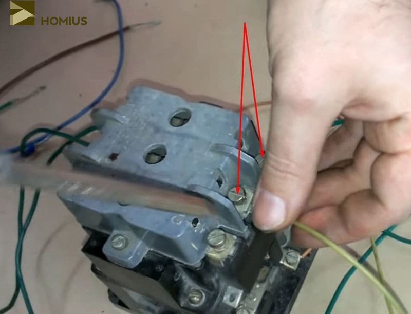
This stage will not be difficult. The first two contacts of the electric motor are connected to the terminals "C1" and "C2" using a wire (in my case, wires with a cross section of 4 mm² were used). However, if the first contact of the engine is immediately tightened tightly, then the second nut should not be screwed on yet.
 Start of connection - the first two wires are in place
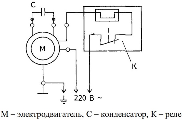
Due to the fact that this motor requires a voltage of 380 V, we need to provide a phase shift. This is achieved by connecting a run capacitor. In my case, its capacity is 20 microfarads, which is quite enough. It is connected to the second and third contact of the electric motor. Thus, the voltage to the third winding will pass through the capacitor, which will create the necessary phase shift. Also, one of the wires of the starting capacitor is connected to the third contact (phase C).
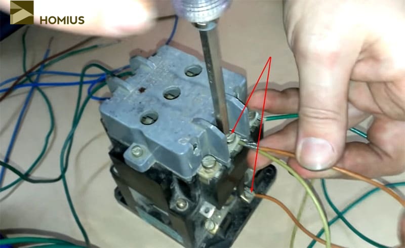
 Contacts of the motor windings of phases B and C. No more connections will be made here
We do not connect the second wire from the starting capacitor, the capacity of which is 50 uF, yet - it will be switched through another magnetic starter of lower power.
Capacitor Precautions
When performing such work, you should be careful. The fact is that capacitors can be charged.This will lead to a harmless, but very unpleasant electric shock. In our case, elements with a voltage of 400 V are used - just such a short-term discharge can be obtained. To avoid such troubles, it is necessary to connect the contacts of the capacitors together. If voltage remains in them, a spark will slip, a click will be heard, after which you can work with the element without fear of an electric shock.
Connecting a borehole pump to power supply with a control unit (automation unit)
Direct connection of the pump is fraught with a quick failure of the pump. The main cause of the malfunction is the idle operation of the pump when the water level drops.
For simple water supply systems, the best option is to include ready-made (factory) automation units in the water supply scheme (example in the photo). Sometimes, such units are called submersible pump control stations. Sometimes a hydraulic controller. They are needed:
- For soft start and soft stop of the pump;
- For automatic pressure maintenance;
- Protection of the pump from "dry pumping", without water;
- Protection of the pump from power surges;
- Protection against lack of water intake;
- Network overload protection.
Block models are different and the set of listed functions may change. The automatic control unit for a borehole pump is a necessary device, and for this reason, reputable companies include it in the pump package, often with limited functionality.
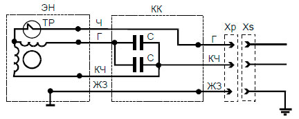
In appearance, the automation unit (hydraulic controller) is quite compact. The connection is also simple, and a simple electrical circuit of a borehole pump with a control unit can be represented as follows.
However, for a longer operation of the automation unit, it is better to consider the scheme for connecting it through a contactor.The controller will ensure the simultaneous activation of the automation unit with the submersible pump.
What is important to know?
The wiring diagram and methods of connecting a device such as a circulation pump to electricity can have different versions. The choice of a particular option is determined by the features heated object, as well as the place where the device is located. There are two possibilities to connect it:
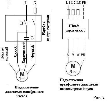
- direct connection to the mains 220 V;
- connection to an uninterruptible power supply, which, in turn, is connected to a 220 V or 220/380 V network (in the case of a three-phase UPS).
Choosing the first method, the consumer runs the risk of being left without heating in the event of a long power outage. This option can be considered justified only with a high degree of reliability of power supply, which reduces the likelihood of a long power outage to a minimum, and also if there is a backup source of electrical energy at the facility. The second method is preferable, although it requires additional costs.
This is interesting: Proper connection of the generator to the house - connection steps
Further switching: we work with a working magnetic starter
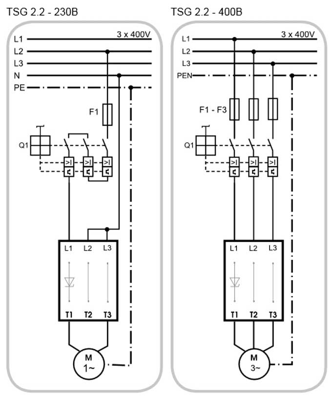
Here we also connect the supply wires - they come from the introductory machine. In this case, the phase wire is connected to the contact "L1" of the working starter, and the zero (neutral) wire to "L2". "L3" will not be activated due to the lack of a three-phase system.
 Connecting the supply wires to the magnetic starter
Immediately connect one of the sides of the electromagnet coil, without which the starter cannot work
When choosing equipment, you should pay special attention to its operating voltage. It can be 220 or 380 V
In the latter case, the starter will not work. Here the connection is made by installing a jumper from the neutral wire contact to the coil terminal.


![The network cable is not properly connected or may be damaged [Solved]](https://fix.housecope.com/wp-content/uploads/c/2/e/c2e87c5d482c29a73a76abb1823cfddd.jpeg)

 Setting the jumper from the supply terminal to the coil
Why ELM327 won't connect to ECU?
The main reasons why the user cannot connect the ELM327 Bluetooth Mini autoscanner with a car (OBD2):
- A poor quality or defective adapter is being used. If the device does not work and does not find a smartphone, the problem may be a faulty board or damage during operation.
- To connect via USB, a defective or damaged cable is used that does not connect and does not communicate with the Android device. If Mini Elm Bluetooth "does not see" the OBD 2 diagnostic output, you need to check the integrity of the cable and make sure that there is no damage to the insulation.
- The firmware is "lost" or outdated. If the software version does not match the firmware of the program used for verification, then the equipment not only does not see the old ones, but also does not look for new devices.
For which vehicles is the ELM327 suitable?
The operation of car adapters EML327 YUSB is possible on certain car models:
- Chevrolet Niva;
- VAZ 2105, 2107, 2110, 2114, 111740, Kalina;
- UAZ Patriot;
- Lada Granta, Priora;
- TAGAZ;
- GAZ 31105, 2217;
- Acura Integra, RSX, 2.3 DCI;
- Alfa Romeo 166, 147, Spider;
- Audi A4, A6, TT;
- BMW 316, 318, E46, 325, 328, E90, 520, 540, 740, 760, X3, X5, Z3, 320, 530, X6;
- Buick LeSabre, Rendezvous;
- BYD F3;
- Chevrolet Astro, Avalans, Camaro, Cavalier, Captiva, Colorado, Corsica, Impala, Lacetti, C10, Silverado, TrailBlazer, Ventur, Starcraft;
- Cherie Amulet, A13;
- Chrysler Cirrus, Cruiser, Grand Voyager, Interpid, Sebring;
- Citroen C2, C3, C5, Cxo, Xsara, Picasso;
- Daihatsu;
- Daewoo Lanos, Matiz, Nexia;
- Dodge Caravan, Dakota, Interpid, Neon, Ram;
- Fiat Doblo, Punto, Marea, Stilo;
- Ford Crown, E350, Escape, Escort, Explorer, Fiesta, Focus, Fusion, Maverick, Mondeo, Mustang, Prob, Ranger, S-Mac, Scorpio, Taurus, Windstar, Galaxy, T280, Transit, Tourneo;
- GMC;
- Honda Accord, Civic, CR-v, R-v, Fit, Element, Odyssey, Passport, Prelude;
- Hyundai Accent, Elantra, Getz, Matrix, I20, Tiburon, Solaris, Santa Fe, Grand Stareh;
- Infiniti;
- Isuzu;
- Jaguar;
- Jeep Cherokee, Grand Cherokee, Wrangler;
- Kia cerate, Rio, Spectra, Sedona, Sorento, Soul, Carnival, Bongo;
- Lexus;
- Mazda Demio, 3, 323, 6, CX7, MX-5, RX-8, Xedos;
- Mercedes;
- Mitsubishi Montero Sport, Carisma, Galant, Diamond, Colt, Eclipse, Lancer, Outlander, Space, Pajero;
- Nissan Altima, Almera, Beetle, Maxima, Murano, Pathfinder, Primera, Sentra, Vingroad, Tiida, Note, Navarra;
- Opel Astra, Corsa, Zafira, Vectra, Omega, Vivaro;
- Peugeot 206, 307, 308, 406;
- Pontiac;
- Porsche;
- Renault Logan, Duster, Megan, Safran, Sandero, Twingo, Clio, Espace, Laguna, Scenic, Traffic, RX-4;
- Saab 9-5, 900;
- Saturn;
- Seat Toledo, Leon, Ibiza, Cordoba, Toledo;
- Skoda Felicia, Octavia, Fabia;
- Smart;
- Ssang Yong;
- Subaru Forester, Impreza, Legacy, Outback;
- Suzuki Igniz, Vitara, Wagon;
- Toyota Auris, Avensis, Avalon, Camry, Karina, Crown, Corolla, Matrix, Land Cruiser, Rav4, Vista;
- Volkswagen Golf, Jetta, Passat, Polo, Santana, Rabbit, Tuareg, Caddy, Tuaran, Tiguan, Transporter;
- Volvo 960, S40, S60, S70, S90, V40, V70, XC70, XC90.
Breakdowns and repair of the float switch
There are some of the most common float failures.They can be eliminated with your own hands, but for this you must act strictly in the specified order.
Float switch works on the principle of leverage. He is responsible for connecting the terminals, due to which the pump motor receives power, and their separation. In some cases, rust and dirt accumulate inside the plane where the terminals touch. Because of this, the float works first with drops, and then completely stops functioning. To eliminate the breakdown, you will need to disassemble and thoroughly clean it without touching the wires.
To avoid clogging in the future, you need to study the purpose of the pump and its float. Equipment for pumping clean drinking water must not be used to handle contaminated liquids.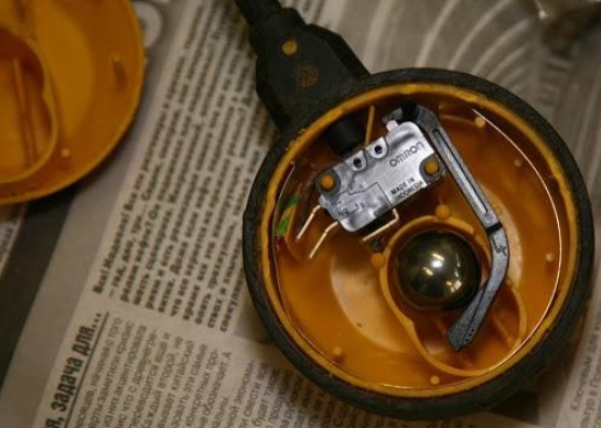
Sometimes the device stops functioning due to a break in the wire connecting it to the pump itself. You can check this by connecting a second wire in parallel. If after that the equipment began to work, then the old wire will need to be removed, installing a new one instead.
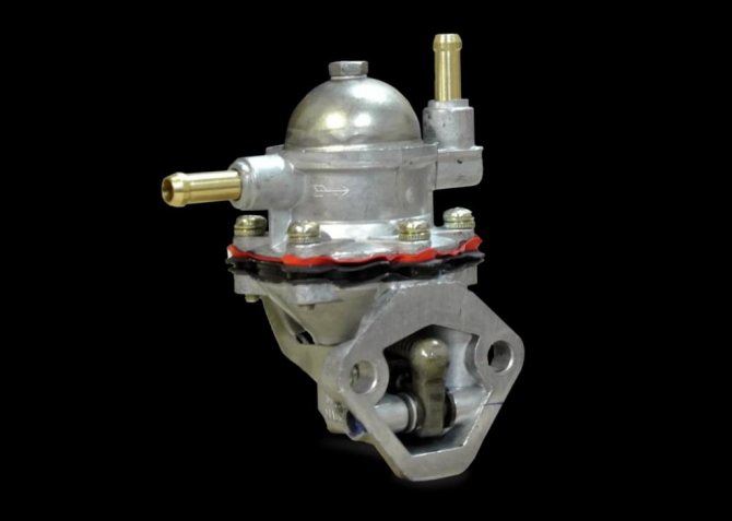
carbureted engine
First, a few words about the well-known mechanical fuel pump. It pumps fuel in cars with a carburetor. The key element is the diaphragm, which moves up and down to deliver fuel from the tank to the carburetor. The design provides for a system of valves, thanks to which the injection of gasoline is ensured and its return to the fuel line is prevented.
The movement of mechanical parts is carried out directly from the engine itself, for this, where the gasoline pump is located, its drive is provided in the cylinder block. Fuel injection can be carried out manually, using the provided lever. The pump does not require an independent lubrication system, as it is included in the line common with the engine.
Features of equipment installation
There are two pump mounting options:
- The self-priming device is mounted next to the water source. A special submersible hose is lowered into the water at one end, and attached to the pump with the other.
- The submersible device is attached to the pipe. If it is a flexible hose, then an addition to the fasteners can be a cable, which is attached at one end to the pump, the second to any stable element with a well. A flexible mounting option is preferable, as it allows you to adjust the immersion depth of the unit. The pump is completely immersed in water. Most of these devices do not tolerate dry operation. Therefore, it is always worth monitoring the level in the well or purchasing a pump with a float switch that will protect the device in the event of a lack or critically low water level.
It is recommended to install a check valve on the pipe itself, which will keep water in the system.
The submersible equipment installation algorithm includes how many points:
- All pipes are installed. If the pump will be installed on a rigid pipe, then it is recommended to put a small piece of flexible hose between it and the main channel for moving water into the house, which will dampen engine vibrations.
- The following are connected to the device: - a cable, - an electric wire, - a hose.
- The pump is smoothly lowered to the bottom of the well.
- When the unit touches the bottom, the entire structure should be raised to a height of half a meter to a meter from the point of contact.
- The cable must be firmly fixed, the wire connected to the network, the hose connected to the rest of the system and laid in the attachment channels.
- It is recommended to provide the upper hole of the well with a cover to prevent foreign objects and dirt from entering the system.
Electrical connection should be made only to a grounded source using a circuit breaker according to the following scheme:
Borehole pump electrical connection diagram
During the installation of the pump, you may need metal-fluoroplastic bushings, their options can be viewed here
Before the first start.
Before turning on for the first time, you must either immerse the motor in water if it is submersible, or fill it with water if it is surface. This information is not related to the topic of the current article. Perhaps I will write about it in another article.
If we have checked and prepared everything, then we flip the switch and the motor starts to work. This means that we have connected everything correctly!.
We run to the pump and watch with bated breath as the pressure rises. We have a manometer for this. Suppose it has grown to 1.5 atmospheres and the pump has turned off. Hooray! Everything is working. It remains only to set the relay to the desired pressure. But before that, we turn on the water in the toilet (we shout to someone from our relatives, or call if the house is big) and watch how the pressure starts to drop. Suppose it dropped to 1 atmosphere and the pump turned on. Yes! Everything really works.
Ways to automate water wells
The simplest and most inexpensive way to automate wells is to install them on a mechanical pressure regulator.If the pressure created by the water is too low, then the contacts of the pumping equipment are closed, and then it is turned on. After shutting off the water supply, the tap must be closed and the pressure level increased.
The installation of a pressure switch equipped with a pressure gauge is carried out at any point in the pumping system, the disadvantage of which is the lack of protection against "dry running". The pressure switch supplies electricity to the equipment if the pressure starts to drop. The pump will continue to run until the entire system fails. Its operation must be regulated, therefore, a hydraulic accumulator is built into the system, which performs the following functions:


- prevention of frequent switching on of the pump;
- taking over the water hammer that occurs in the event of a sharp closing of the crane.
A hydraulic accumulator is a tank, for the manufacture of which ferrous metal or stainless steel is used. The device can be painted blue. The capacity of the device is 5-500 liters. The number of switching on of the pumping system depends on the volume of the tank.
Installing a well automation unit is another way to control the functioning of the pump. These systems are advanced, so their cost is 10-15 times higher than the price of a simple relay. The automation system should include the following items:
- LCD display;
- dry running protection;
- pump jamming protection;
- automatic start;
- hydraulic accumulator.
The most expensive type downhole automation pumps is considered a frequency converter. It outputs the frequency needed to maintain pressure in the pumping system. It becomes operational only after opening the 2nd tap and increasing the water flow.
When using frequency converters, the minimum motor speed is used. It is 20-30% of the nominal, which is indicated in the technical documentation for the device. If the requirement is not met, the device may fail.
Connecting a borehole pump without auxiliary equipment
Without a control unit, an automation unit and other auxiliary equipment, the pump power cable is connected to a pre-installed electrical outlet with a grounding contact.
Grounding of the borehole (submersible) pump is mandatory. For a direct ground connection, the GZSH (main ground bus) of the house is used, which in turn is connected to the existing ground loop of the house.
An electrical cable with a grounding conductor is used to supply power to the pump socket. The supply voltage of the submersible pump is 220 volts.
To power the pump, you need to select a separate electrical group and protect this group with a circuit breaker. The rating of the circuit breaker is calculated from the electric power of the pump. So for pumps up to 3000 W you need a 10 Amp circuit breaker, for higher power pumps you will need a 16 Amp circuit breaker.
Important! This connection cannot be considered as correct. It only shows the general principle of connecting a well pump
The lack of automation in controlling the operation of the pump will lead to malfunctions when water disappears (dry running) in the supply system.
This is interesting: Is a radiant heating system suitable for heating a one-story house: explain in detail
Let's summarize the work done
If you have the necessary components to assemble such a circuit, this connection option is worthy of attention. This applies even to those who will use the machine only for sharpening or straightening knives 2-3 times a year. After all, it does not require costs, and sometimes it may be simply necessary. I really hope that what I have told today will be useful to any of the readers of this resource.
The editors of Homius invite home craftsmen and craftsmen to become co-authors of the Stories section. Useful stories from the first person will be published on the pages of our online magazine.
Previous Stories How to make an extraordinary illuminated mirror: The Homius Reader Experience
Next STORIES do-it-yourself balloons Without Extra Investment: The Homius Reader Experience


