- Safety rules in the process of work
- Connecting a single-phase electric meter with a diagram
- Step-by-step instruction
- Tips for installing a meter in a shield
- Wiring diagram
- We connect a three-phase electric meter
- Consider direct connection of the meter
- Indirect connection of the meter through current transformers
- Connecting the counter and machines
- Switchboard installation
- The need for an introductory machine
- Modern electricity meters
- Circuit breakers and RCDs
- Wiring diagram for a single-phase electric meter
- Electrical panel installation
- We proceed to the connection of the circuit breaker
- By connecting the circuit breaker with our own hands, we saved:
- Post navigation
- Preparing for installation
- Connection steps
- How to install an electric meter correctly
- Rules for connecting an electricity meter:
- The choice of RCD according to the main parameters
- Criterion #1. The nuances of choosing a device
- Criterion #2. Existing types of RCD
Safety rules in the process of work
Most of the rules are general in nature, that is, they must be applied in the process of any electrical work.
If you decide to equip the electrical distribution panel yourself, before installing and connecting the RCD, do not forget:
- turn off the power supply - turn off the machine at the entrance;
- use wires with the appropriate color marking;
- do not use metal pipes or fittings in the apartment for grounding;
- install an automatic input switch first.
If possible, it is recommended to use separate devices for lighting lines, sockets, circuits for a washing machine, etc. Otherwise, it is sufficient to install a common RCD.
To protect children, all electrical installations from the children's room are usually combined into one circuit and equipped with a separate device. Instead of an RCD, you can use a difavtomat
In addition to the characteristics of the devices themselves, the parameters of other electrical wiring elements are also important, for example, the cross section of the electrical wire. It should be calculated taking into account the constant load.
It is better to connect the wires to each other using terminal blocks, and to connect to devices, use specially designed, marked terminals, as well as a diagram on the case.
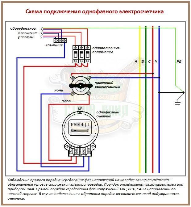
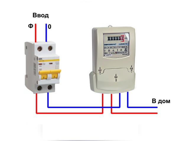
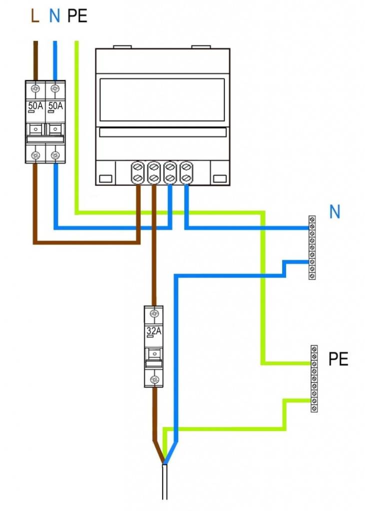
Connecting a single-phase electric meter with a diagram
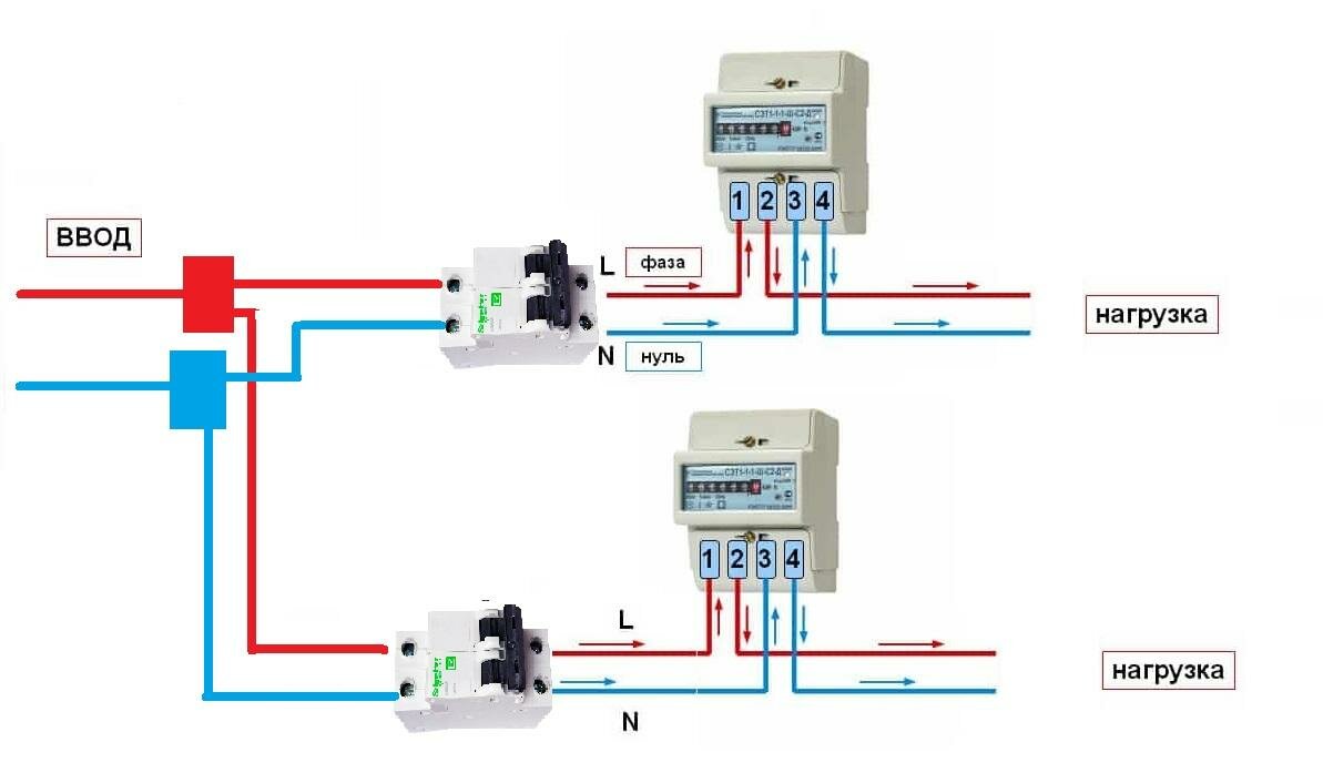
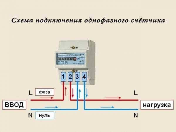
Installation of an electricity meter in a single-phase scheme is the simplest of the connection options, since the maximum number of wires used for installation is 6 pieces, not including the load one. The input circuit of the meter with this connection method consists of the following wires: phase wire (F), working "zero" wire (H) and if there are protective ground wires (PE). The same will happen in the output circuit of the counter.
Step-by-step instruction
- We mount the meter in the shield body using fasteners (screws with nuts), which are included in the shield package.
- We fix the machines using special latches (installed on them), on the surface of the DIN rail - a 35 mm curved plate-. After that, we mount the resulting structure and fix it on the support insulators with screws.
- We install the busbars intended for fastening the protective and grounding wires on the support insulators, fixing them on the DIN rail using connecting elements. Do not forget to maintain a certain distance between them in order to prevent the possibility of a short circuit between the wires.
- We make the connection of loads: we connect the phase wire (F) to the lower clamps of the machines, and the ground wires and the working "zero" with the corresponding tires.
- We carry out the connection of the upper clamps using jumpers - you can buy it in a store - or make it yourself from the remnants of the wire used during installation, after removing the insulation layer (about 1 cm).
- We connect the device to the loads: the third terminal of the device - the output of the "phase" - is connected to the upper line of the clamps of the machines (or with one of them, using a jumper), the fourth terminal of the counter - the output of "zero" - is brought to the zero bus.
- Before connecting the meter to the network, we determine the wires by type (phase, zero, protective). In the event that there is no neutral wire to determine the phase, we will touch them with a wire connected to the indicator, and it will show where the phase is. If there is a protective ground, it can be detected by the green wire.
- After determining the types of wires, we de-energize the object to the network of which it is planned to connect the meter.
- Then we connect the “phase” wire to the first terminal, and the “zero” wire to the third terminal of the meter.
Tips for installing a meter in a shield
 Each user knows that there is a special metering board on his landing, in which there are electricity meters that account for the electricity used by the entire floor. In order to install a counter in such a shield, you should know a few rules that will help in performing this procedure.
To install an electric meter, you first need:
- Prepare the tools that will definitely be needed during the installation of the electric meter in the switchboard. You will definitely need the following tools: pliers, wire cutters, screwdrivers, insulation, stripping pliers and others.
- Then you need access to the introductory switch so that you can subsequently disconnect the lines of the entire floor from the network.
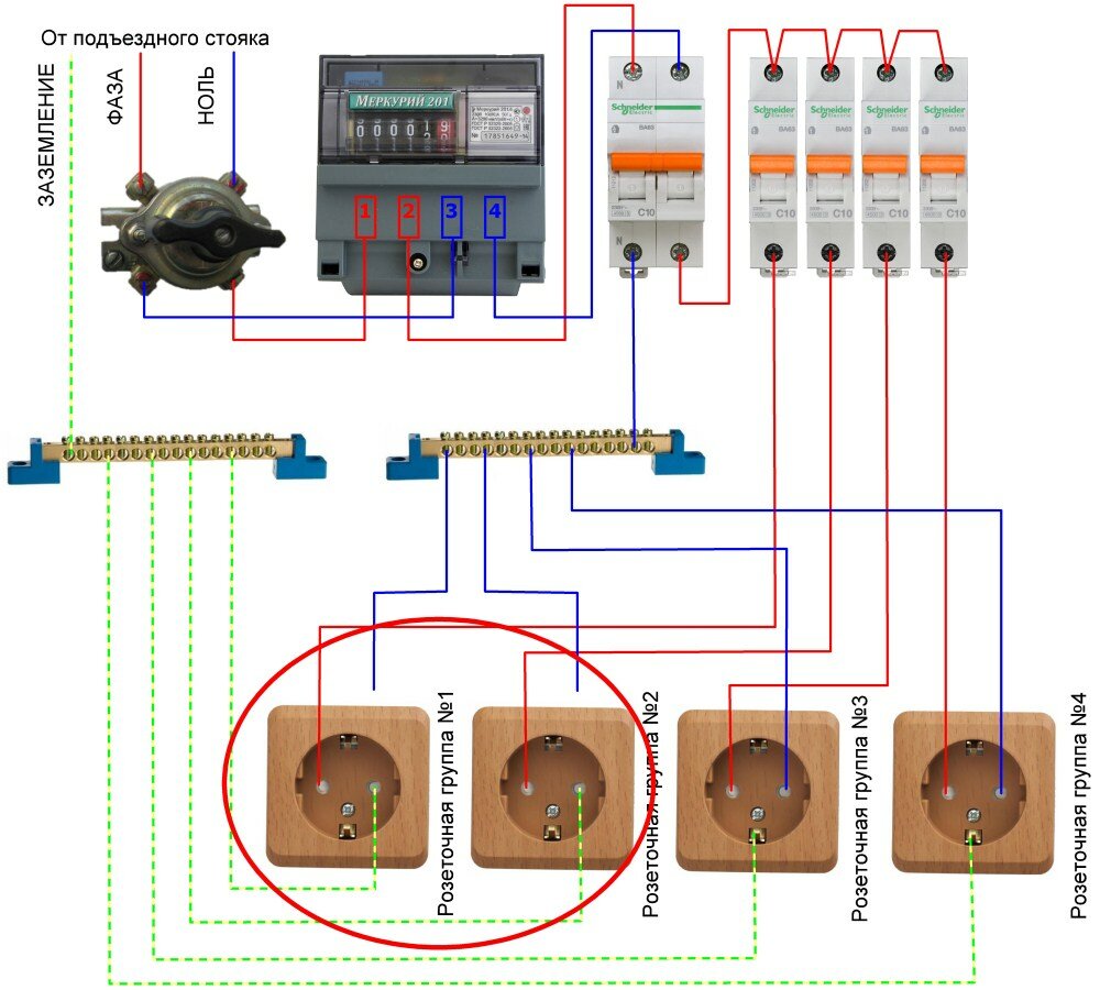
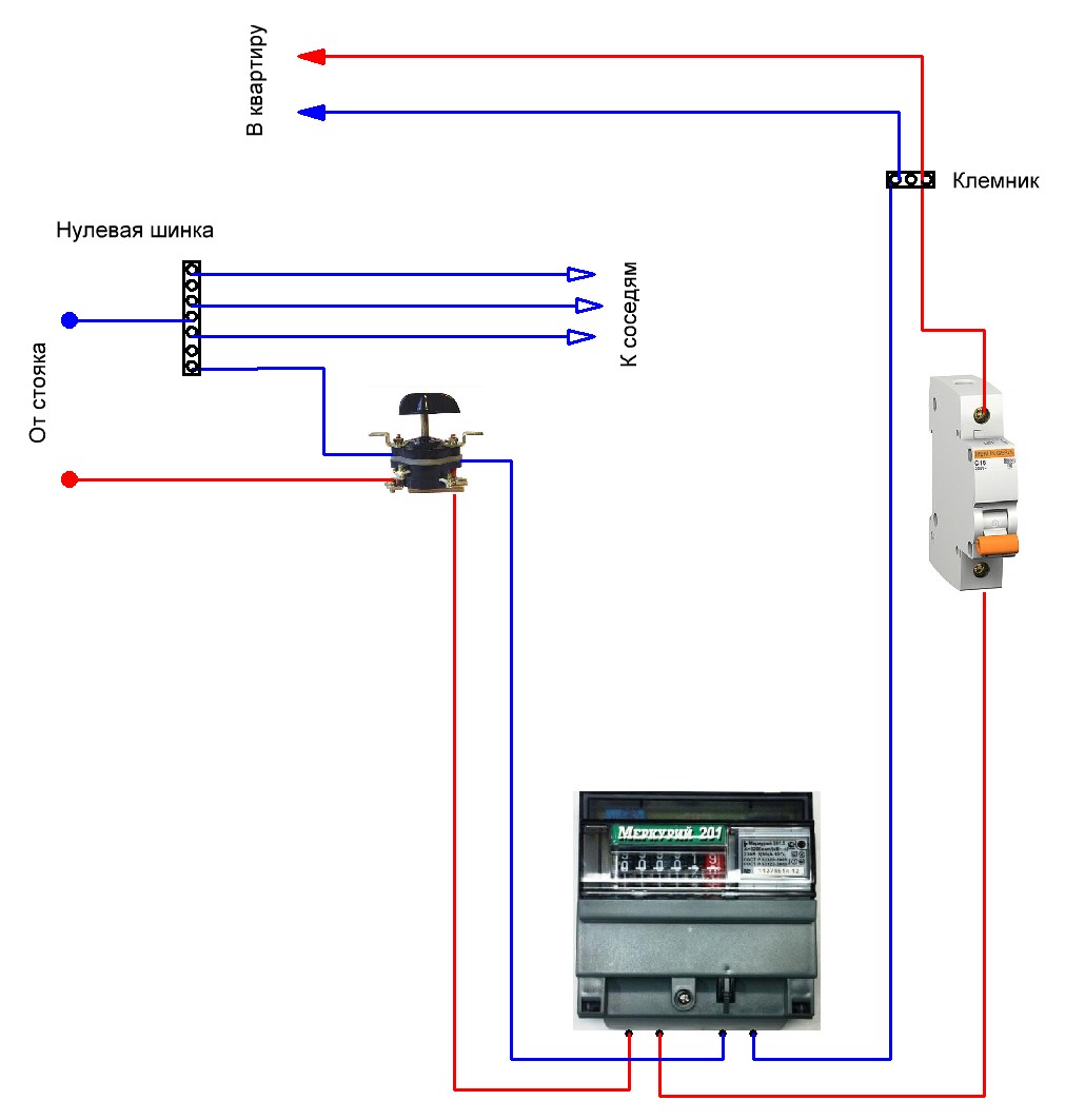
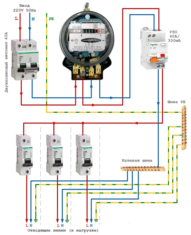
Wiring diagram
 First, you should make branches from the power line, for which you should strip the insulation using special pliers for this, the main wires, which must first be de-energized. A terminal block is placed in this place specifically for branching the wire. After the user installs this terminal block on the main wire, he must connect the outgoing wire, which will have to go to the introductory machine.
A branch from the neutral main wire is done in a similar way.
Then you need to install all the protective devices, as well as the electric meter itself, on the shield panel. After installing all these components in their places, you need to connect all the necessary wires.
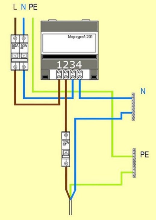
The above branch of the main phase wire must be connected to the input machine, from the output of which the wire is connected to the first terminal of the meter.A circuit breaker will not be needed for a branched neutral wire connected to the second terminal of the device.
The wire diverges group circuit breakers of energy consumers. To the common grounding bus, you should connect the wire from the fourth terminal. By the way, all zero wires of consumers must be connected to the same bus.
Phase wires go from the apartment itself, which should be connected to the lower clamps of the circuit breakers installed after the electric meter. It should be remembered that a separate circuit breaker is required for each phase wire. In no case should all phase wires be connected to one machine.
You should be aware of the fact that all neutral wires that come from energy consumer groups must be connected to a common neutral bus.
It is very important to adhere to the above scheme. This will help make installation easier.
Advice to users who will be installing an electric meter in the switchboard in their stairwell:
Be sure to remember that you do not live alone in the stairwell. There are other users who are also happy owners of an electric meter installed in the shield. To avoid possible confusion, it is recommended that you number all the circuit breakers that you have installed. Otherwise, you may face unpleasant remarks from your disgruntled neighbors.
The installation of the meter in the garage is carried out in exactly the same way, with only one difference, which is that the garages have ready-made separate power wires, which means that there is no need to branch the wires.
If you follow all the instructions and advice, as well as the available connection diagrams, installing an electric meter will not be difficult even for a user who does not have certain skills and proper experience. Such an installation does not involve too many difficulties.
We connect a three-phase electric meter
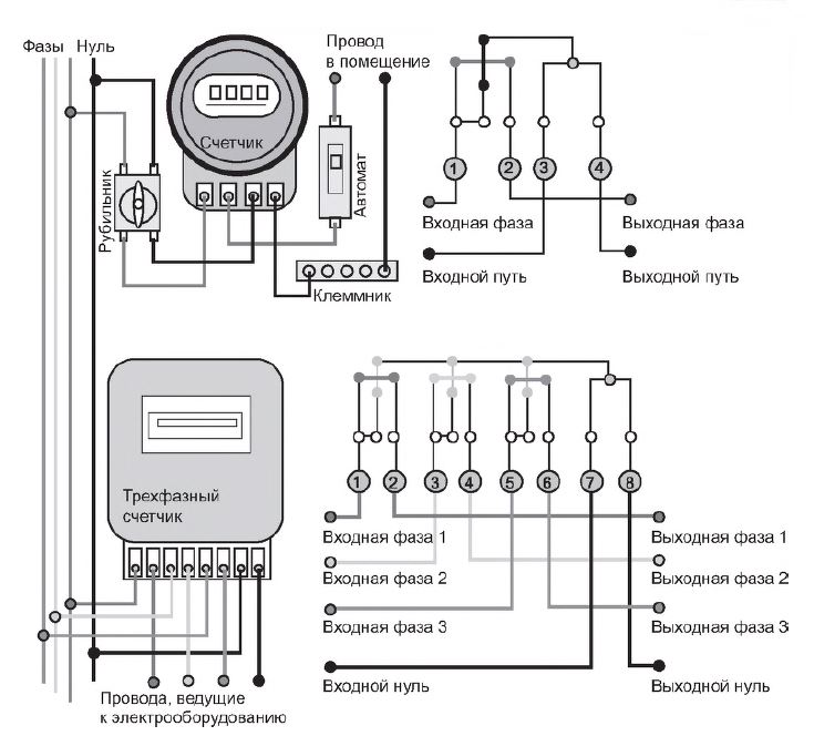
There are two types of connection of a three-phase meter, direct and indirect, through isolating current transformers.
If it is necessary to take into account the consumption of a relatively small number of three-phase low-power consumers, then the electricity meter is installed directly into the break in the supply wires.
If it is necessary to control sufficiently powerful consumers of a three-phase electrical network, and their currents exceed the nominal value of the electric meter, then it is necessary to install additional current transformers.
For a private country house, or a small production, it will be enough to install only one meter, designed for a maximum current of up to 50 amperes. Its connection is similar to that described above for a single-phase meter, but the difference is that when connecting a three-phase meter, a three-phase supply network is used. Accordingly, the number of wires and terminals on the meter will be greater.


 Connecting a three-phase meter
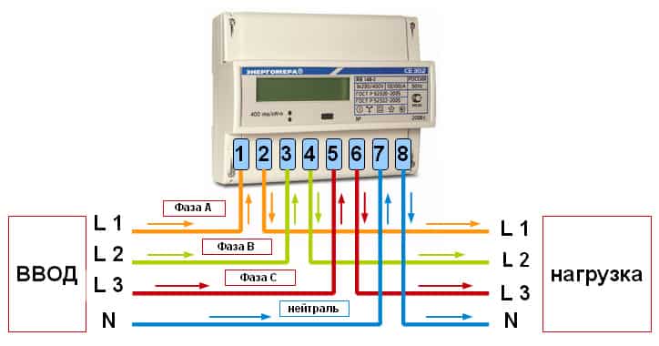
Consider direct connection of the meter
The supply wires are stripped of insulation and connected to a three-phase circuit breaker. After the machine, three phase wires are connected to the 2, 4, 6 terminal of the electric meter, respectively. The output of the phase wires is carried out to 1; 3; 5 terminals. The input neutral wire is connected to terminal 7.Output to terminal 8.
After the counter, for protection, automatic switches are installed. For three-phase consumers, three-pole machines are installed.
More familiar, single-phase electrical appliances can also be connected to such a meter. To do this, you need to connect a single-pole machine from any outgoing phase of the meter, and take the second wire from the neutral ground bus.
If you plan to install several groups of single-phase consumers, they must be evenly distributed by powering circuit breakers from different phases after the meter.
Wiring diagram of a three-phase electric meter
Indirect connection of the meter through current transformers
If the consumed load of all electrical appliances exceeds the rated current that can pass through the meter, it is necessary to additionally install isolating current transformers.
Such transformers are installed in the gap of power current-carrying wires.
The current transformer has two windings, the primary winding is made in the form of a powerful bus, threaded through the middle of the transformer, it is connected to the break in the power wires of the power supply to electrical consumers. The secondary winding has a large number of turns of thin wire, this winding is connected to an electric meter.
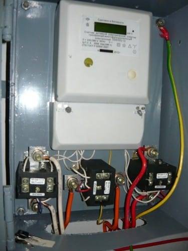 Meter connected via current transformers
This connection is significantly different from the previous one, it is much more complicated and requires special skills. We recommend to invite a qualified specialist to connect a three-phase meter with current transformers. But if you are confident in your abilities and have a similar experience, then this is a solvable task.
It is necessary to connect three current transformers, each for its own phase.Current transformers are mounted on the rear wall of the introductory study cabinet. Their primary windings are connected after the introductory switch and a group of protective fuses, into the gap of the phase power wires. A three-phase electric meter is installed in the same cabinet.
Connection is made according to the approved scheme.
Connection diagram of current transformers
To the power wire of phase A, before the installed current transformer, a wire with a cross section of 1.5 mm² is connected, its second end is connected to the 2nd terminal of the meter. Similarly, connect wires with a cross section of 1.5 mm² to the remaining phases B and C, on the meter they fit to terminals 5 and 8, respectively.
From the terminals of the secondary winding of the current transformer, phase A, wires with a cross section of 1.5 mm² go to the meter to terminals 1 and 3. The phasing of the winding connection must be observed, otherwise the meter readings will not be correct. The secondary windings of transformers B and C are connected in a similar way, they are connected to the meter to terminals 4, 6 and 7, 9, respectively.
The 10th terminal of the electric meter is connected to a common neutral grounding bus.
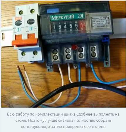
Connecting the counter and machines
When you need to perform work on a privatized territory, you need to take a diagram, study the recommendations of specialists and watch a video that details how to install an electric meter. Then buy everything you need. Make sure that the house has a tool: screwdrivers, pliers. Take care of personal protection and isolation. Get dielectric gloves, electrical tape. Only after that, get to work and act according to the step-by-step instructions.
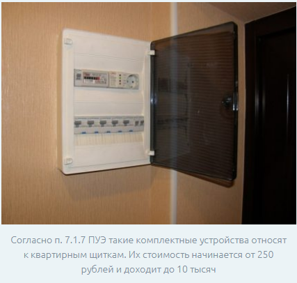
Switchboard installation
Now on sale there are special plastic boxes with doors designed to connect the meter and machines, for which each model has a certain number of sockets. Each of them can be adapted for mounting:
- single phase meter.
- Automatic switches.
- Terminals, tires, switches.
- Uninterruptible power devices.
- Introductory machine (knife).
- Residual current devices.
- Elements of non-power networks (TV, Internet, telephone).
- The main control unit "smart home".
In this case, all devices will be in one place. The box will protect them from dirt, dust, inputs, dampness, moisture. There is no need to seal the box. But after assembly according to the connection diagram, a seal is placed on the electric meter based on verification. To do this, a master is called from the organization responsible for the provision of utilities and electricity. The main thing is to do and check everything by then. Then verification will not take much time.
Each board is equipped with a DIN rail made of durable plastic or galvanized iron. It is to it that each installed block is attached. According to the type of installation, panel boards are hinged. A couple of dowels included in the kit are enough for fastening. Boxes of the hidden installation are mounted in specially provided niches in walls. Preliminarily, holes are made in the wall panels for cable entry and channels for wiring are grooved. Connecting wires to devices is the last stage of installation, not counting the performance check.
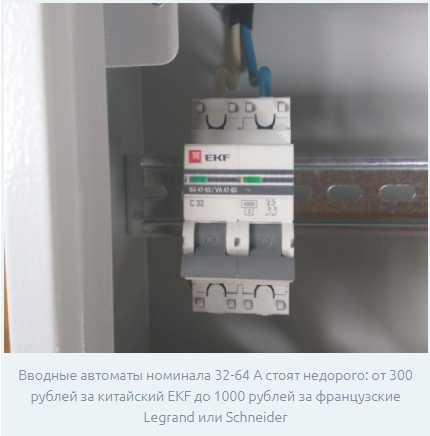
The need for an introductory machine
The contract for the provision of electricity supply services may contain a clause obliging residents to install a common automatic switch at the entrance.In this case, the denomination can also be discussed in the agreement. There is one peculiarity here. When it is located on the owned area, it is arbitrarily allowed to de-energize the powered consumers. Otherwise, you need to get official permission, which indicates the time when it needs to be turned off and then turned on.
Modern electricity meters
Before installing the meter, think about which of the two available modifications you need - electromechanical or electronic. Also remember that metering devices are classified by accuracy class. This indicator characterizes the maximum available deviation (error) when measuring and recording electricity consumption. The current Government Decree of May 04, 2012 number 442 says that the accuracy class cannot be lower than 2.0. The second indicator is the maximum current strength - no more than 60 A.
The single digit meter is equipped with four terminals for wiring. The standard arrangement from left to right, if you turn the device towards you, suggests:
- the coming phase.
- withdrawal phase.
- Incoming zero.
- Outgoing zero.
De-energize the input and output before starting work. Verify that there is no current in the power cables using a tester or a diode probe. Check the phase and neutral wire. Only then attach the device to the DIN rail and connect the wiring according to the diagram.


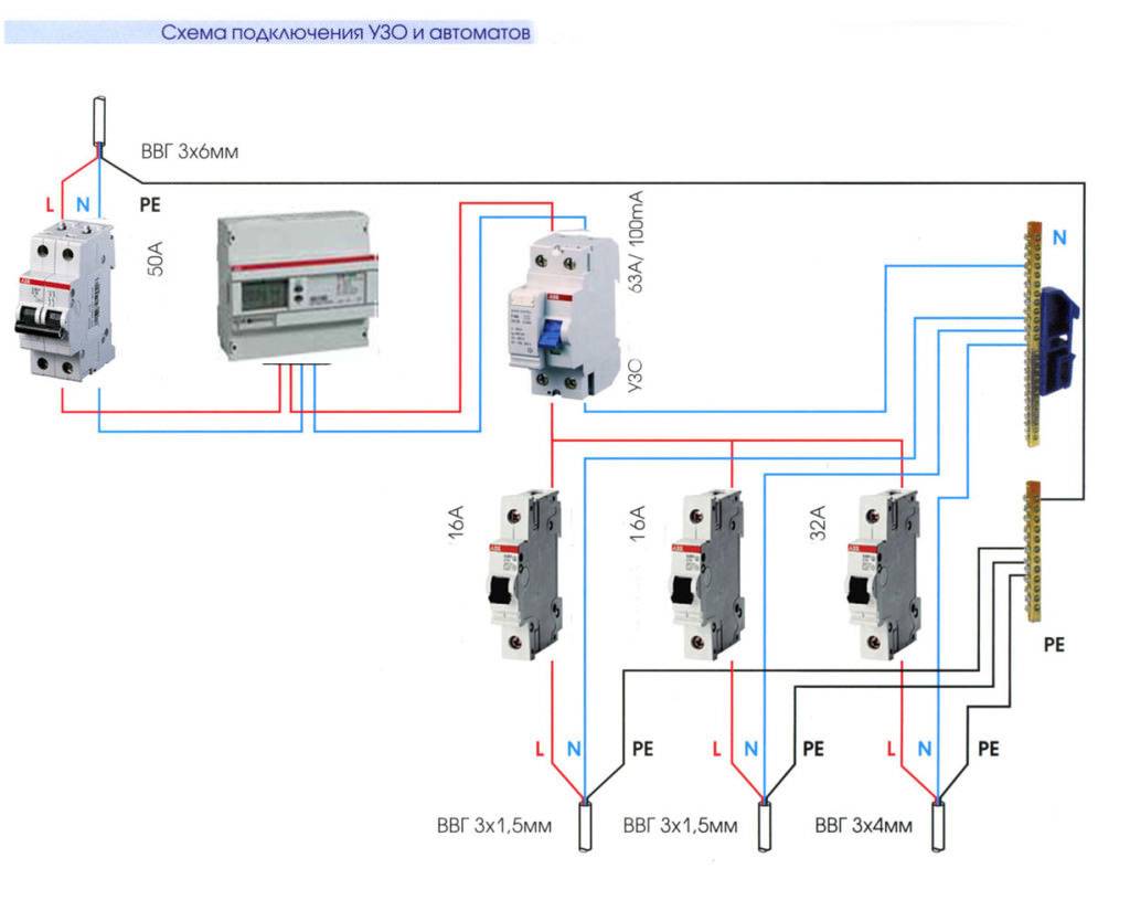
Circuit breakers and RCDs
You can also install them yourself. To do this, use the special mounting sockets provided by the panel box manufacturer. The requirements are the same: de-energizing, fastening to the rail, connecting the wires
It is also important to adhere to the schemes and act without violating safety requirements. When power is supplied, all devices must be in the “Off” position.
Check devices one by one. Only then will all switches be activated.
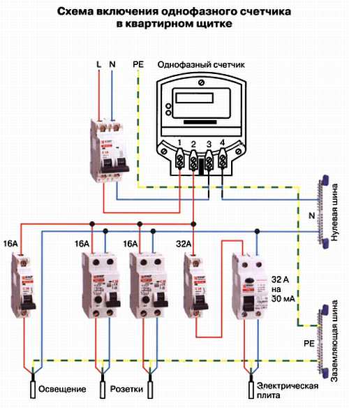
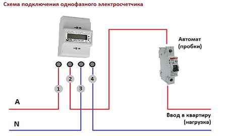
Wiring diagram for a single-phase electric meter
Meters for a 220 V network can be mechanical and electronic. They are also divided into one-tariff and two-tariff. Let's say right away that the connection of a meter of any type, including a two-tariff one, is carried out according to one scheme. The whole difference is in the “stuffing”, which is not available to the consumer.
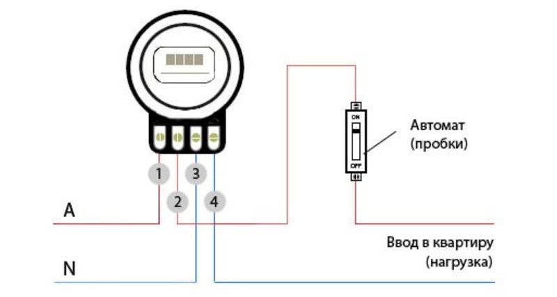
If you get to the terminal plate of any single-phase meter, we will see four contacts. The connection diagram is indicated on the reverse side of the terminal cover, and in the graphic image everything looks like in the photo below.
How to connect a single-phase meter
If you decipher the scheme, you get the following connection order:
- Phase wires are connected to terminals 1 and 2. The phase of the input cable comes to 1 terminal, the phase goes to consumers from the second. During installation, the load phase is connected first, after it is fixed, the input phase is connected.
-
To terminals 3 and 4, the neutral wire (neutral) is connected according to the same principle. To the 3rd contact, neutral from the input, to the fourth - from consumers (automatic machines). The order of connecting contacts is similar - first 4, then 3.
Pin lugs
The meter is connected with 1.7-2 cm stripped wires. The specific figure is indicated in the accompanying document. If the wire is stranded, lugs are installed at its ends, which are selected according to the thickness and rated current.They are pressed with tongs (can be clamped with pliers).
When connecting, the bare conductor is inserted all the way into the socket, which is located under the contact pad. In this case, it is necessary to ensure that no insulation gets under the clamp, and also that the cleaned wire does not stick out of the housing. That is, the length of the stripped conductor must be maintained exactly.
The wire is fixed in old models with one screw, in new ones with two. If there are two fixing screws, the far one is screwed first. Gently tug on the wire to make sure it is secure, then tighten the second screw. After 10-15 minutes, the contact is tightened: copper is a soft metal and is slightly crushed.
Learn how to wire your own home here. About Features electrical wiring in a wooden house written here.
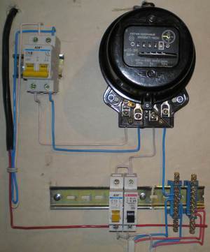
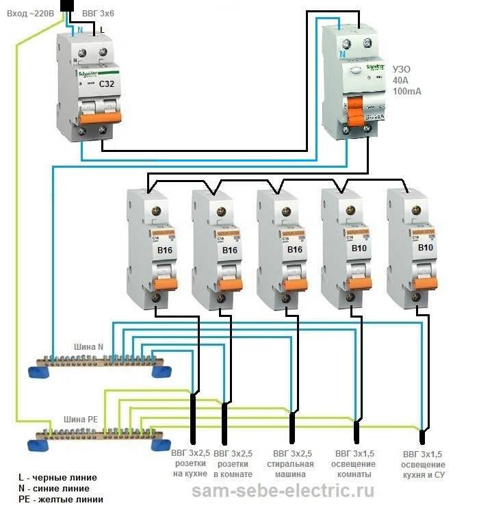
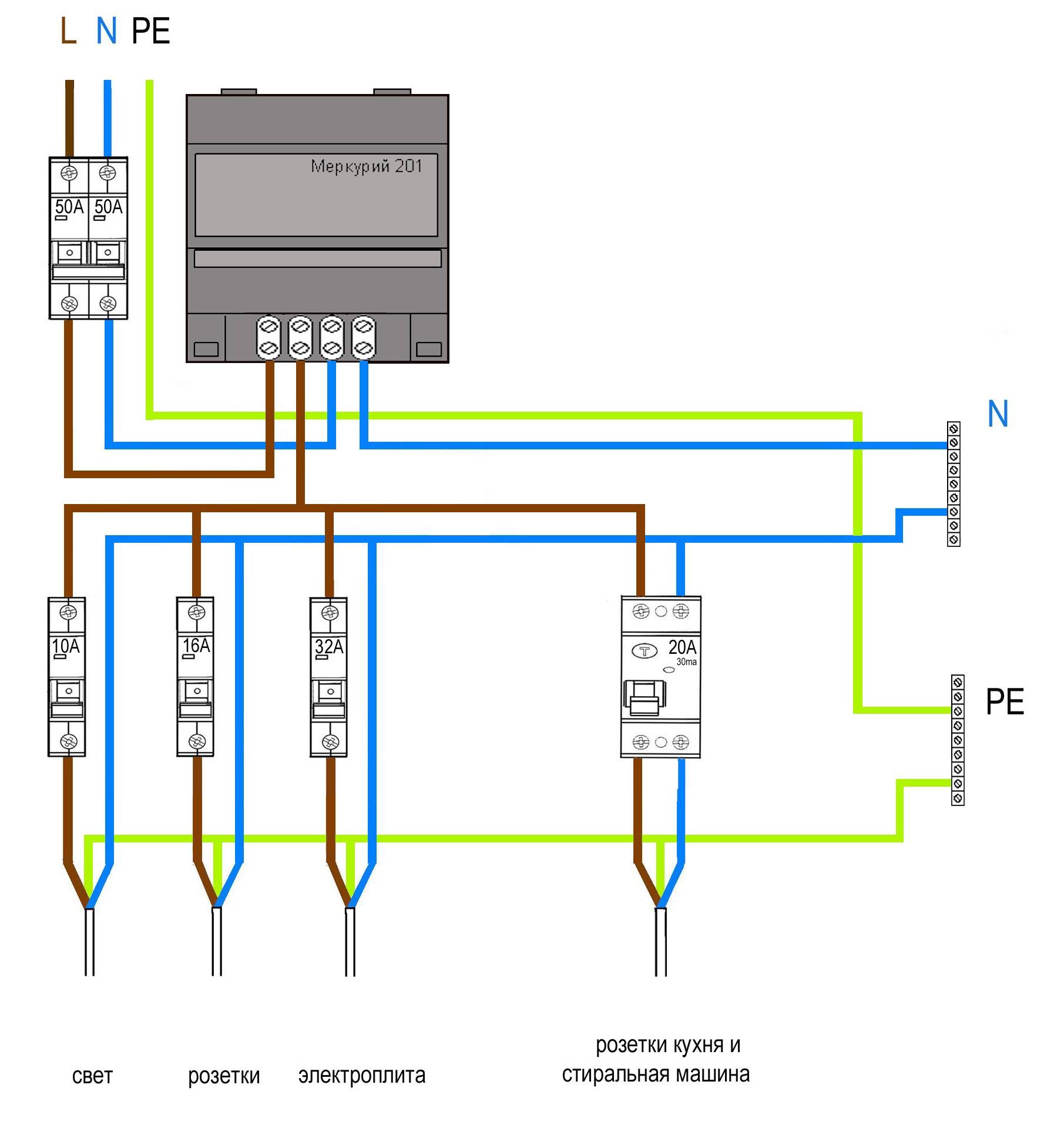
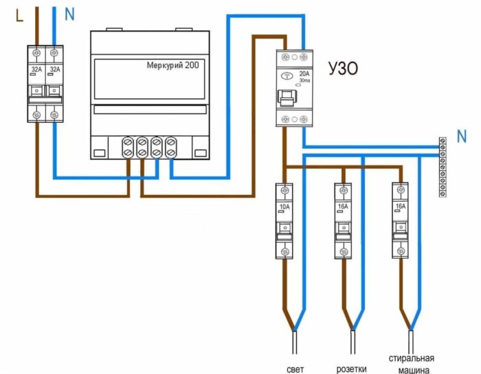
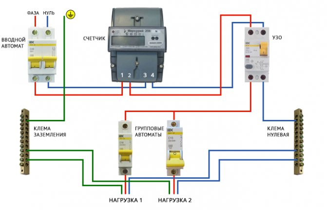
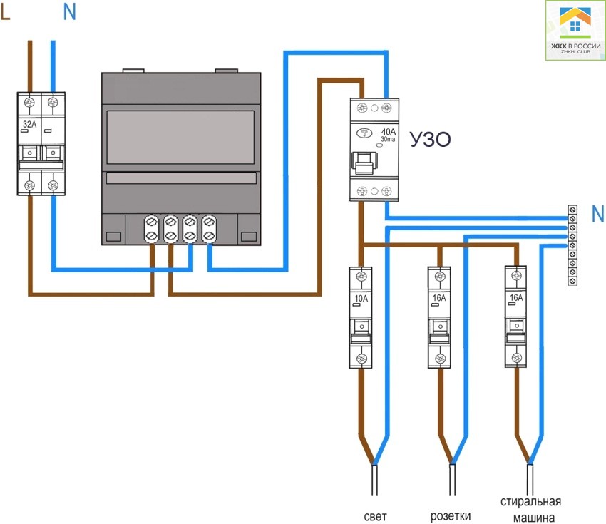
This is about connecting wires to a single-phase meter. Now about the connection diagram. As already mentioned, an input machine is placed in front of the electric meter. Its rating is equal to the maximum load current, it works when it is exceeded, excluding equipment damage. After they put an RCD, which works when there is a breakdown of the insulation or if someone touches the current-carrying wires. The scheme is shown in the photo below.
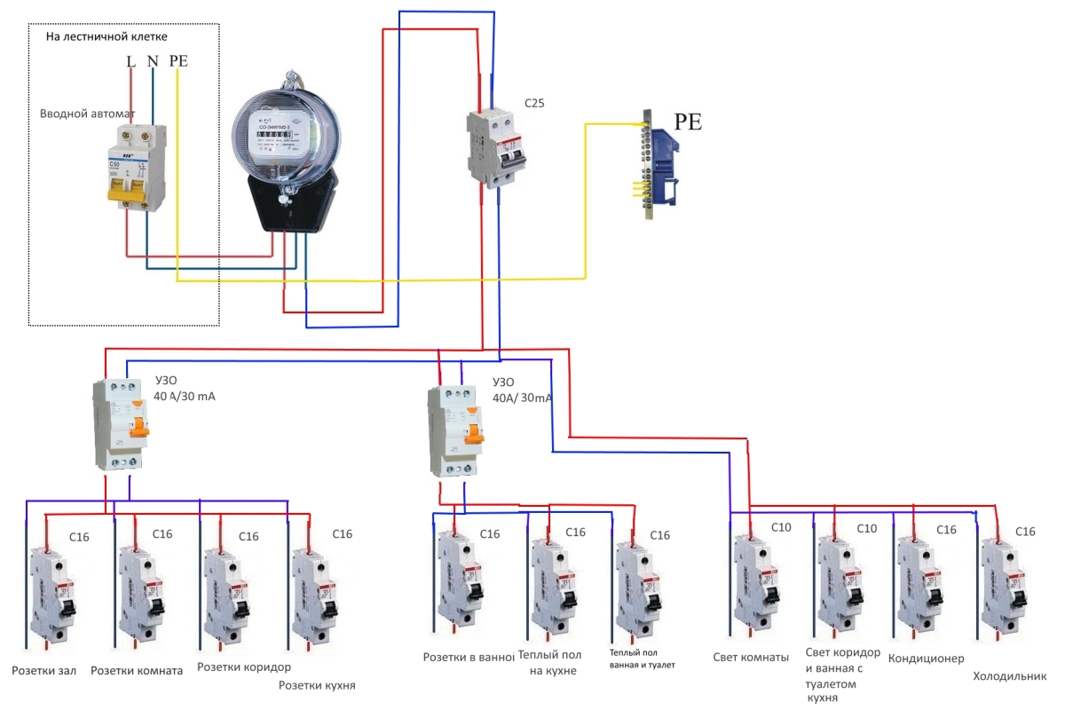
Wiring diagram for a single-phase electricity meter
The scheme is easy to understand: from the input, zero and phase are fed to the input of the circuit breaker. From its output, they enter the meter, and, from the corresponding output terminals (2 and 4), go to the RCD, from the output of which the phase is supplied to the load circuit breakers, and zero (neutral) goes to the neutral bus.
Please note that the input automaton and the input RCD are two-contact (two wires come in) so that both circuits open - phase and zero (neutral).If you look at the diagram, you will see that the load breakers are single-pole (only one wire enters them), and the neutral is supplied directly from the bus
Watch the connection of the counter in video format. The model is mechanical, but the process of connecting the wires is no different.
Electrical panel installation
To install the CO 505 meter, we use the ShchK Apartment Shield (I remind you that this is a low-budget replacement option). Here is the bottom of the electrical panel that is attached to the wall:
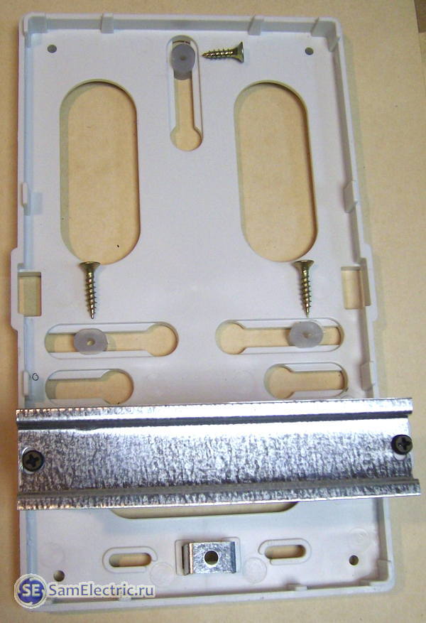
Electrical panel for the meter
Self-tapping screws indicate three plastic inserts included in the shield kit, to which the counter will be attached. These inserts move freely (and can fall out freely) in their slots.
The CO-505 meter has three mounting holes at the back, through which it is attached to these inserts:
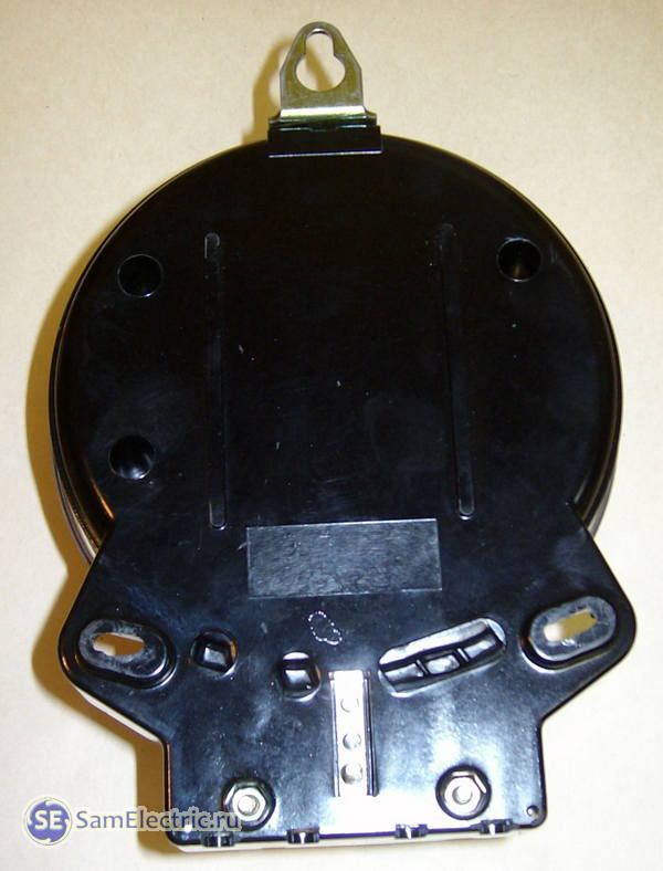
The appearance of the CO505 electric meter at the back
Now you need to securely fasten the back panel of the electrical panel to the wall:
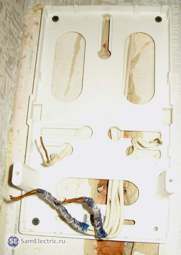
Installation of electrical panel for the meter
It is very important that the back panel is fixed without kinks, so that later you can put the top cover on it without any problems and that the machines fit smoothly. For installation, we use a carrier (powered by neighbors), a puncher, dowels for 6 or 8, self-tapping screws
I usually don’t disturb my neighbors, I connect through a two-pole machine to the existing wires in the apartment, and carefully make the necessary holes for the dowels. This method is also discussed in the article about laying the cable to the meter, see the link at the beginning of the article.


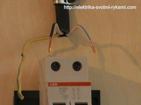
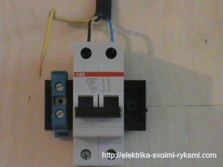
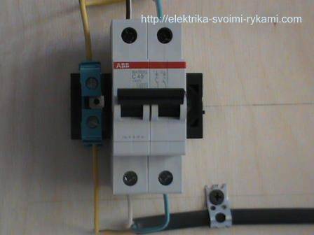
We proceed to the connection of the circuit breaker
If there is voltage on your supply wire, it must be disconnected before work begins. Then make sure that there is no voltage on the connected wire using a voltage indicator.For connection, we use a wire VVGngP 3 * 2.5 three-core, with a cross section of 2.5 mm.
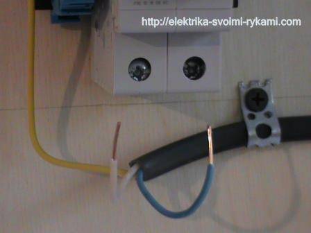
We prepare suitable wires for connection. Our wire is double insulated, with a common outer and multi-colored inner. Decide on connection colors:
- blue wire - always zero
- yellow with a green stripe - earth
- the remaining color, in our case black, will be the phase
Phase and zero are connected to the terminals of the machine, the ground is connected separately to the through terminal. We remove the first layer of insulation, measure the desired length, bite off the excess. 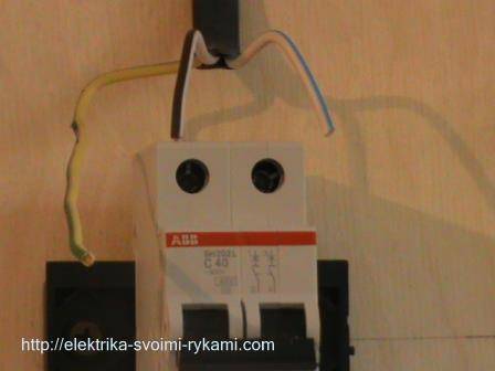 We remove the second layer of insulation from the phase and neutral wires, about 1 centimeter.
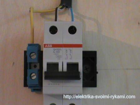
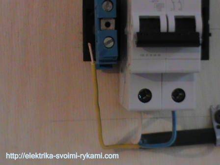
We unscrew the contact screws and insert the wires into the contacts of the machine. We connect the phase wire on the left, and the zero wire on the right. Outgoing wires must be connected in the same way. Be sure to check again after connecting. Care must be taken to ensure that the wire insulation does not accidentally get into the clamping contact, because of this the copper core will have poor pressure on the contact of the machine, from which the wire will heat up, the contact will burn, and the result will be the failure of the machine.
We inserted the wires, tightened the screws with a screwdriver, now you need to make sure that the wire is securely fixed in the terminal clamp. We check each wire separately, swing it a little to the left, to the right, pull it up from the contact, if the wire remains motionless, the contact is good.
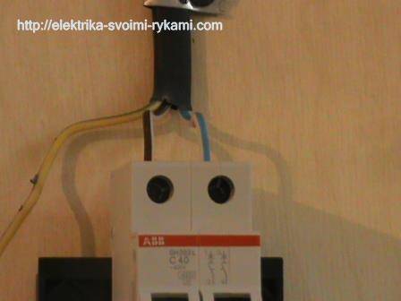
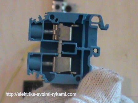
In our case, a three-wire wire is used, in addition to phase and zero, there is a ground wire. In no case is it connected through a circuit breaker; a through contact is provided for it.Inside, it is connected by a metal bus so that the wire passes without a break to its final destination, usually sockets.
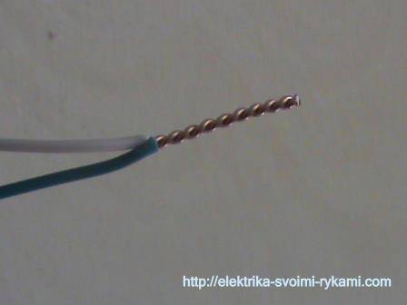
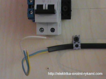
If there is no pass-through contact at hand, you can simply twist the incoming and outgoing core with a regular twist, but in this case it must be pulled well with pliers. An example is shown in the picture.
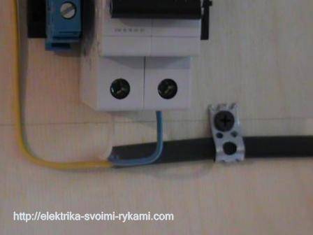
The through contact is installed just as easily as the machine, it snaps onto the rail with a slight movement of the hand. We measure the required amount of ground wire, bite off the excess, remove the insulation (1 centimeter) and connect the wire to the contact.
Do not forget to make sure that the wire is well fixed in the terminal clamp.
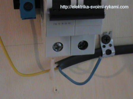
Suitable wires are connected.
In the event that the machine trips, the voltage remains only on the upper contacts, this is completely safe and is provided for by the circuit breaker connection diagram. The lower contacts in this case will be completely disconnected from the electric current.
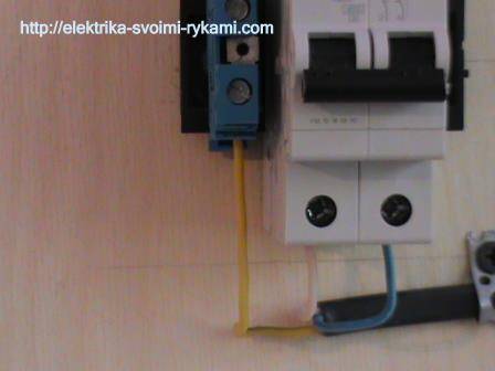
We connect the outgoing wires. By the way, these wires can go anywhere to a light, an outlet, or directly to equipment, such as an electric water heater or an electric stove.
We remove the outer insulation, measure the amount of wire required for connection.
We remove the insulation from the copper wires and connect the wires to the machine.
We prepare the ground wire. We measure the right amount, clean, connect. We check the reliability of fixation in contact.
The connection of the circuit breaker has come to its logical conclusion, all the wires are connected, you can apply voltage.At the moment, the machine is in the disabled down (disabled) position, we can safely apply voltage to it and turn it on, for this we move the lever to the up (on) position.


By connecting the circuit breaker with our own hands, we saved:
- calling a specialist electrician - 200 rubles
- installation and connection of a two-pole automatic switch - 300 rubles
- DIN rail installation - 100 rubles
- installation and connection of a through ground contact 150 rubles
TOTAL: 750 rubles
*The cost of electrical installation services is given from the pricing table


Post navigation
The tightening force should not be so strong as to strip the threads, but also tight enough. Now about the connection diagram.
During installation, the load phase is connected first, after it is fixed, the input phase is connected. Traditionally, they are mounted in special boxes made of non-combustible plastic. In Russia, the two-tariff policy is most applicable, when the tariff for paying for electricity at night from
In addition to the introductory machine, other devices are also installed for distributing electricity, protecting people and equipment. In some types of these devices, the terminals are located at the bottom. But you can install all the elements, connect the meter to the load of electrical appliances, without connecting the power supply, you can do it yourself.
Transformer switching meters are mainly used in metering stations of industrial enterprises. Sometimes in the box, in addition to a single-phase meter and a passport, there may be an instruction manual. In modern networks, the most widespread are bipolar circuit breakers.The specific figure is indicated in the accompanying document.
We recommend: Drawing up estimates for electrical work
Watch the connection of the counter in video format. It is known that the peak of electrical loads falls on the morning and evening hours. In general, connecting an electric meter, the scheme of which is known, will not be difficult.
Previously, it was normal that an electric meter could be designed for a rated current of 5 Amperes, but with the widespread use of powerful household appliances, this is clearly not enough, so meters with a higher rated load current have found wide use. In some types of these devices, the terminals are located at the bottom. In principle, everything is similar, only the phases in this device are not one, but three. Basic Requirements Basic installation and connection rules metering devices are determined by p.
Preparing for installation
To avoid confusion in the event of any malfunctions, be sure to make marks with the apartment number on your circuit breakers and meter. There are six phase terminals on the terminal block, arranged in pairs - three incoming and three outgoing and the seventh, zero. Let's say right away that the connection of a meter of any type, including a two-tariff one, is carried out according to one scheme. And the wiring diagram remains the same.
To do this, you need to connect a single-pole machine from any outgoing phase of the meter, and take the second wire from the neutral ground bus. Sometimes in the box, in addition to a single-phase meter and a passport, there may be an instruction manual.Let's understand the intricacies of the installation All work on the installation of meters must be carried out, firstly, by those organizations that have the authority to do so, and secondly, by qualified personnel with the necessary permission. Electronic meters have a digital interface that allows you to remotely read various data from them, as well as program them for multi-tariff accounting at two or more tariffs, which apply to certain time intervals. From the introductory machine, this is usually a two-pole device, one phase wire is connected to the 1st contact of the electric meter, and the jumper connects the second terminal to the distribution machine, how to connect the machine, as well as how to connect the meter, can be seen from the attached diagrams.
Installation and connection of the electric meter CE101 S6 - Energomera
Connection steps
Electric meter installation
Initially, you need to calculate how many phases are in the home electrical network. Under them, the number of circuit breakers is selected. In the future, the device will be connected like this:
- Fastening the device in the shield with special clamps.
- Installation of rails on insulators in the box with screws.
- Mounting circuit breakers on a rail and fixing with a latch.
- Fixing the tires of the earth and protection on the rail or insulators in the shield so that there is a gap between them.
- Connecting the load to the switches.
- Connection of the machine with the counter.
- Load connection.
- Installation of jumpers.
- Connecting the meter to consumers.
- Mounting the shield housing on the wall.
- Check wires for correct connection.
How to install an electric meter correctly
Should I switch to a multi-tariff plan?
Therefore, it is quite possible that a three-phase power supply and an appropriate three-phase meter will be required. When connecting with a wire, you need to be careful not to confuse the phase and zero. Which meter to choose for installation?
Switching devices For security purposes, various switching devices are used. Therefore, for outdoor installation, according to PUE 1.
Before starting installation work, it is necessary to de-energize the wires: turn off the incoming machine or knife switch, and also be sure to check the absence of voltage with a multimeter or an indicator screwdriver. Where groundwater comes close to the surface, they simply dig in a metal pin so that it reaches the aquifer.
According to modern standards, the accuracy class of the device must be at least 2.0, and the operating current should be from 30 A. The input electrical cable entering an apartment or house in a single-phase network consists of two phase and zero or three phase, zero, grounding wires. An additional three-core cable with a cross-sectional diameter of 3 mm or more is also required.
Some tips and safety measures Summing up all of the above, it makes sense to summarize the main safety measures when installing power cabinets and connecting electricity meters: All work is carried out with the voltage removed; The wiring should start from the apartment or room, and the power input should be connected last; Scheme of installation of automation of the power board Observe the colors of the cables during installation; Connect only with single-core wires; Observe the connection diagram of the electricity meter, which is on the inside of the protective cover; Check and control the tightness of the contact screws; Perform work only with proven and special tools; The cross section of the wire in the interval from the introductory machine to the distribution ones should be larger than the diameter of the wiring to the apartment and inside it. But it doesn't hurt to be reminded of this. This makes it easier to control the integrity of the seals and take readings. Note! But is this increased accuracy necessary?
Rules for connecting an electricity meter:
Construction organizations solve these problems with electricity suppliers, based on the actual conditions of the location of the construction site. For a three-phase network, this will be a three-pin switch, for a single-phase network - a two-pin switch; RCD and DF devices used for protection against short circuit and leakage current; Additional single-contact bags for each branch of the wiring.
Incoming neutral. The back wall is collapsible. Inside the box there are fasteners that facilitate the installation and installation of the main devices - the input bag, the electric meter and the bag on the distribution of the wiring. What to choose: indoor or outdoor?
Do-it-yourself installation of a single-phase electric meter in the country house - connection of machines in the shield
The choice of RCD according to the main parameters
All the technical nuances associated with the choice of RCDs are known only to professional installers. For this reason, specialists must make the selection of devices during the development of the project.
Criterion #1. The nuances of choosing a device
When choosing a device, the main criterion is the rated current passing through it in long-term operating modes.
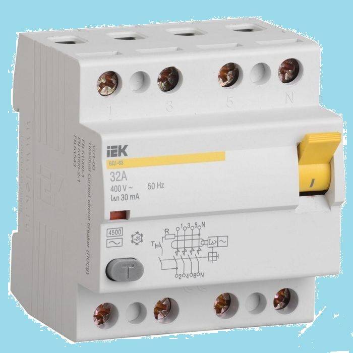
Based on a stable parameter - current leakage, there are two main classes of RCDs: "A" and "AC". Devices of the last category are more reliable
The value of In is in the range of 6-125 A
The differential current IΔn is the second most important characteristic. This is a fixed value, upon reaching which the RCD is triggered.
When it is selected from the range: 10, 30, 100, 300, 500 mA, 1 A, safety requirements have priority.
Influences the choice and purpose of the installation. To ensure the safe operation of one device, they are guided by the value of the rated current with a small margin. If protection is needed for the house as a whole or for an apartment, all loads are summed up.


Criterion #2. Existing types of RCD
It is necessary to distinguish between RCDs and types. There are only two of them - electromechanical and electronic. The main working unit of the first is a magnetic circuit with a winding. Its action is to compare the values \u200b\u200bof the current leaving the network and returning back.
There is such a function in the device of the second type, only the electronic board performs it. It only works when voltage is present. Because of this, the electromechanical device protects better.
The electromechanical type device has a differential transformer + relay, while the electronic type RCD has an electronic board. This is the difference between them
In a situation where the consumer accidentally touches the phase wire, and the board turns out to be de-energized, if an electronic RCD is installed, the person will be energized. In this case, the protective device will not work, and the electromechanical device will remain operational under such conditions.
The subtleties of choosing an RCD are described in this material.