- Chandelier LED with remote control
- Necessary accessories and tools for work
- What tools and materials will be needed to install a double switch
- Connection diagram and features
- Switch installation
- Selecting a connection scheme
- 2 point wiring
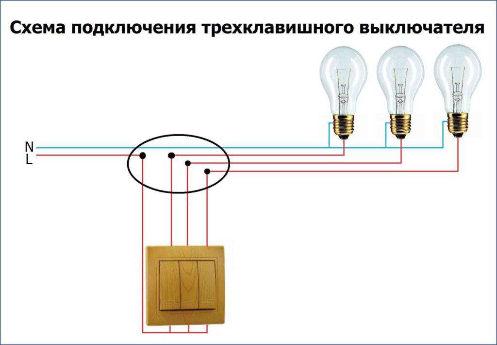
- Three-point connection
- Varieties of switching devices
- Video - Feed-through switch or impulse relay?
- Designations on the device case
- Two-gang switch and its connection, diagram and photo
- Let's get started mounting the switch on 2 keys
- Connection
- Illuminated two-gang switch
- Options and Selection Tips
- Scheme of using two pass-through switches
- The principle of operation of the pass switch
- Preparatory work
- Connection via socket
Chandelier LED with remote control
In the age of electronics, pulling stranded cables along the walls in order to command the chandelier from different points in the room? Not worth it.
The market is filled with modern fixtures with main and illuminating lamps, which are controlled from the remote control: basic, portable.
When installing such a chandelier, the switch will only perform the function of supplying voltage to the controller, which is hidden behind the decorative cup of the lighting fixture. The most common type of its connection with the remote control is a radio channel.
Before connecting an LED chandelier, you need to understand its device. The electrical part includes the following.
- Receiver-switch (controller) signal and turn on the Wireless Switch lamps (in one case, with a wiring diagram and outgoing antenna).
- Transformers, drivers, power supplies (when using low-voltage lamps and LEDs).
- Sources of light.
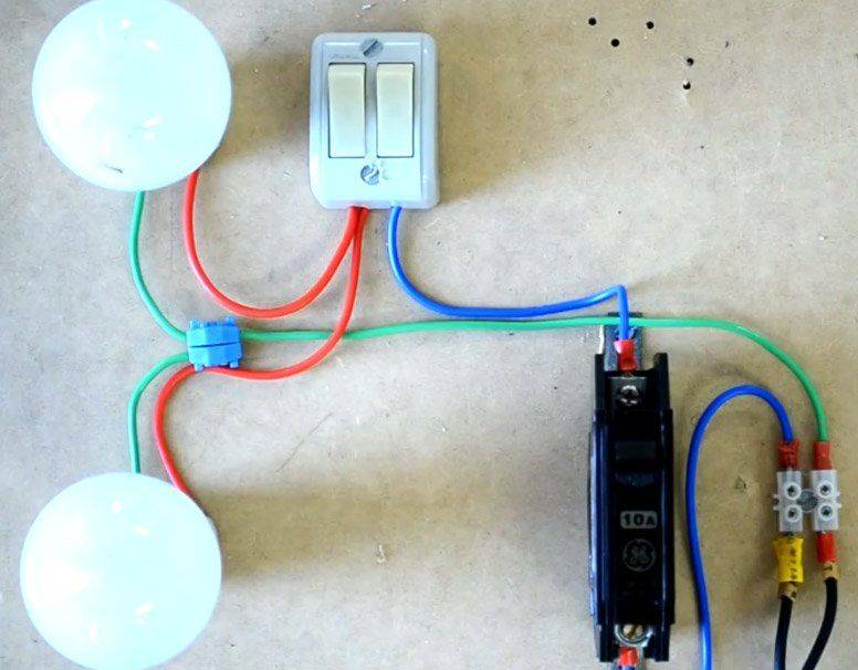
As a rule, in the purchased chandelier, the internal wiring is done. The user only needs to connect zero and phase to the controller. The last one comes from the switch.
Here they are in the photo, in the lower left corner.
The scheme looks like this. There are three users here. Two are halogen bulbs, one is LED.
By pressing the buttons (usually 4) from the remote control, the lamps are turned on / off according to the instructions. If the remote control cannot be used, the switch will act as its role. The chandelier reacts to quick on-off from one to 4 times in the same way as to commands from the remote control.
To attach such a chandelier to the ceiling, a special DIN rail is used.
For a detailed story on how to connect a chandelier with a remote control, see the video:
Necessary accessories and tools for work
To install the switch and connect the consumer to it, you will need the following materials and tools:
- switch - depending on the number of consumers, one-, two- or three-gang switch can be used;
- wire - you need to choose the right wiring, based on the expected load on the network and the presence or absence of grounding among consumers;
- junction boxes are needed for ease of connection, as well as the ability, if necessary, to extend another branch not from the meter, but directly in the room;
- a screwdriver with an indicator, a multimeter - to control the correct connection, as well as to check the absence or presence of power in the network;
- wire cutters and pliers - for the convenience of working with wire;
- electrical tape, terminals - to ensure the safety of connecting and insulating wires;
- glass and fasteners - for reliable installation of the switch in the wall;
- a drill with a blow or a puncher - will be needed when installing hidden wiring.

What tools and materials will be needed to install a double switch
You will need the following tool to complete the installation. Considered for models of two standard versions.
switch for open wiring:
- Electric drill.
- Drill with a diameter of 6 mm (for wood) or a drill with a diameter of 6 mm (for concrete, brick walls).
- Phillips screwdriver for clamping the wire in the terminal contacts and fastening the switch housing.
- A screwdriver is an indicator for determining the presence of voltage in the network.
- Knife for stripping the insulating layer of the wire. (in the absence of a special tool for stripping insulation from cable and wire products). And also a knife is needed to prepare the inlet and outlet holes in the switch body for wires (cable).
- Pliers for crimping flexible wire. If the wire is monolithic, pliers may not be needed. But it is also possible to use crimp lugs that match the cross section of the wire (for flexible wire).
- Dowel with plug 6x40 (standard size is indicated, it may vary depending on local conditions).
- Marker or felt-tip pen for marking "phase / zero" on wires (for safety reasons).
 Screwdriver set with insulated handles + voltage indicator
Switch for concealed wiring.
To install the switch in a network with hidden wiring, you will need the same set of tools as in the previous example, but with a significant addition. You will need a hammer drill with special equipment - a crown for drilling standard holes in concrete and brick walls. Since the working part is recessed into the wall, a perforator is indispensable.
 Drill bit for socket, switch
And you will also need a special mortar to fix the plastic switch case in the drilled hole. For this purpose, building gypsum, plaster, etc.
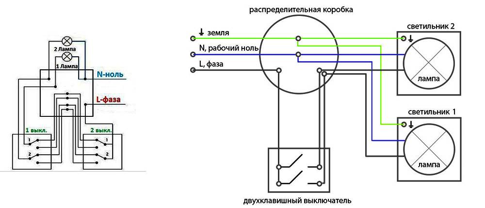
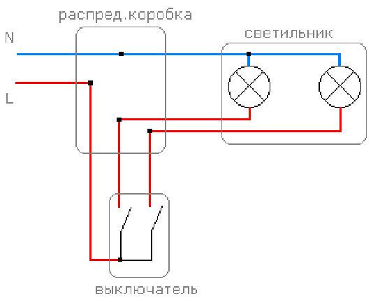
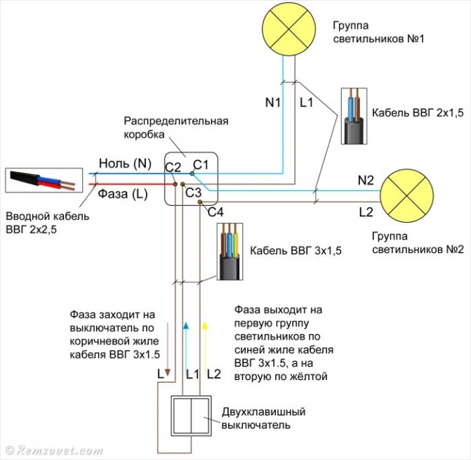
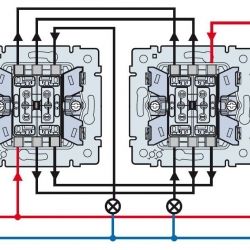
Connection diagram and features

connection diagram
Due to the great similarity with the single-key version, the connection diagram has no fundamental differences.

The process itself will look like this:
- Initially, it is necessary to study the location and purpose of the contacts, sometimes additional information about this is available on the back of the device. However, if it is absent, then it will not be difficult to figure it out: there should be 2 contacts with an output in this variety and traditionally they are located on the opposite side of the only input.
- A phase extending from the distributor is connected to the input contact, and contacts with outputs are designed to control light sources, their number is equal to the number of keys, in this case there will be 2 of them.
- It is advisable to connect the switch in such a way that the central contact is located at the bottom.
- It is necessary to connect 3 neutral wires: from the distributor and from each of the lighting sources.
- The phase wire leaving the distributor is connected to a single input contact in the switch.
- The switch has 2 phase wires, each of them is connected to a similar conductor coming from the lamp.
- Inside the distributor, these phase conductors must be connected to the groups of lamps or separate light sources that are planned to be controlled. After that, both conductors will be switched phases of two groups of lamps.
- In the distributor, it is necessary to identify the neutral wire, which is connected to a similar conductor that goes to the lighting sources. The mechanism can only switch the phases of different groups of devices.
- After all connections are completed, you can start soldering and equipping the twist with an insulating layer, but before that it is recommended to check all connections made.
 The process of connecting a double switch has a number of different nuances, the main features include:
- The installation of a double version of the switch should be carried out exclusively in the socket, the diagonal of which is 67 mm. It not only fits perfectly with the dimensions of the device, but also provides a wide range of different types of mounting. The old-style sockets have a diagonal of 70 mm, since the old devices were larger and do not fit well with modern models. In addition, in the old days they were made of metal, not plastic.
- The preparation of wires depends not only on the type of switch, but also on the type of lamp. This process is carried out in the factory, so if their location does not suit you, you will have to dismantle the device to change these parameters.
- Inside the installation box there are traditionally 3 conductors, the recommended length for them should not exceed 10 cm.
- Some modern models of double switches are of a modular type, that is, they actually consist of 2 single devices. In this case, you will need to supply power to each part of the mechanism, this is done using a jumper, which can be made independently from an ordinary wire. With its help, both mechanisms are connected.


Switch installation
Finally, let's talk about how to mount switches. It doesn't matter how many keys they have. The sequence of work is the same:
- From the junction box, a strobe is lowered vertically down (or up with the bottom wiring).
- At the selected height, a hole is made in the wall for the socket. Usually use a nozzle on a drill - a crown.
- A socket is installed in the hole. The voids between the socket box and the wall are filled with mortar, preferably with good adhesion to concrete and plastic.
- A corrugated hose of small diameter is laid from the junction box to the entrance to the socket. Wires are then passed into it. With this method of laying, it is always possible to replace damaged wiring.
- The switch is disassembled (keys, decorative frame are removed), wires are connected.
- They are installed in the socket, fixed with spacer petals by tightening the fixing bolts.
- Set the frame, then the keys.
This completes the installation and connection of the double switch. You can check your work.
Selecting a connection scheme
We will analyze in detail how to connect correctly.We must not forget that when installing a pass-through switch, it is necessary to pull a three-wire wire.
2 point wiring
List of materials:
- copper cable with three cores;
- a pair of pass-through type switches;
- junction box.
The phase wire must be connected to the common input contact of the first switch. The two output pins are connected to the wires from the input two. The common contact of the second switch is twisted with the wire that comes from the light source. In this case, the second wire from the source must be connected to the zero of the box.
The cross section of 3-core wires is selected based on the power of the light source that is supposed to be controlled.
Three-point connection
List of materials:
- copper cable with three and four cores;
- a pair of pass-through type switches;
- cross switch;
- junction box.
The cross contacts have 4 contacts, 2 for each direction. They are pairs of simultaneous switching. A cable with four cores must be used for this circuit.

At the first and last switching point, conventional through switches are used, and cross switches are used between them. The number of possible points through which the lamps will be controlled is not limited. However, the more there are, the more the complexity of the connection increases.
The connection is as follows:
The 2 pins per output from 1 pass switch must be connected to the wires of the input pair of the next cross switch. This continues until the circuit closes at the extreme switch. The common contact is connected to the wire directed to the light source.
The phase wire is connected to the input contact 1 of the switch, 2 wire to zero of the box. A three-wire wire is pulled to each pass-through switch, while a four-wire wire is pulled to the cross switches.
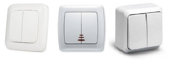
Varieties of switching devices
Switches differ from each other in several ways. In order to choose a suitable option, you need to familiarize yourself with them in more detail - we will present the necessary information in the form of a table.
Table number 1. Switch types.
| View | Description |
|---|---|
| push-button | As a rule, such a device is suitable for call control, so it is installed near the entrance. However, it is not used to control luminaires. |
| Keyboards | This is the standard option that is used to open and close circuits in household electrical networks. |
| Swivel | Such switches are also sometimes installed in residential premises, but most often they can be found in production. After all, they do not have such an aesthetic appearance as the previous options. |
As we have already said, there are single-key devices, as well as two-key, three-key devices. They, in turn, are divided into standard, combined type devices and intermediate ones.
In the first case, we are talking about three-pin switches, in the second, the number of clamps differs in the number of keys. The third option is intended for complex circuits where more than two switching points are required.
In private houses or apartments in multi-storey buildings, devices with keys are often installed.
Sometimes they mount devices on touch control or from the remote control. The third option has gained popularity in recent years.
According to the method of laying electrical wiring, switches are divided into the following types:
- external (overhead switches);
- built-in (hidden).
In the first case, you will need to attach the device directly to the ceiling with screws. The second option involves a method of fastening with the help of special ears that are located along the edges.
Video - Feed-through switch or impulse relay?
If you want to choose the best switch option in the presence of a pass-through device circuit, then you should correctly determine the number of keys (each group of devices should have one key). If you are going to organize only two points to control the lamp, then purchase a standard switch with three contacts. If more points are required, then additional devices will have to be purchased in order to connect to a common chain.


Most often, devices with a key have only two positions - on and off. However, equipment is commercially available with an additional center position (zero) that is intended to open these two circuits.
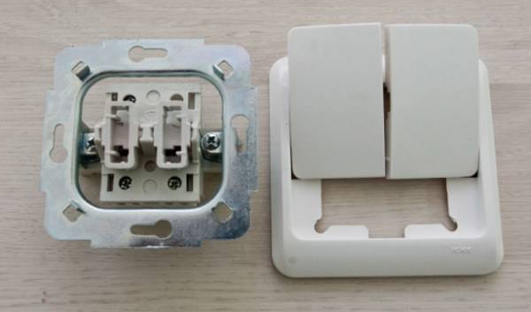
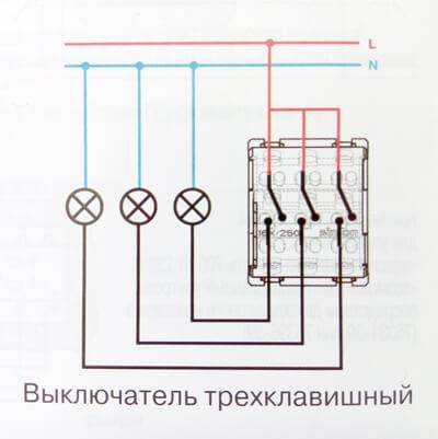
Designations on the device case
On the body of the switching device, where the contacts are located, as a rule, there is a marking with the characteristics of the device. Here the voltage, rated current and degree of protection of the product are indicated.
switches
For standard light bulbs, you must choose a fixture marked - "A". If you plan to install gas lamps, then you should choose a switch marked - "AX".
When the light is turned on in gas lighting fixtures, there is a sharp fluctuation in starting currents. When installing standard bulbs and LEDs, the fluctuation will not be so pronounced.It turns out that the switch must be designed for such a load, otherwise the possibility of melting of the contacts in the terminals is not excluded. Therefore, in the case of gas-light lamps, an appropriate device is required.
The terminals for fixing the electrical wiring also differ from each other:
- on screws with a pressure plate;
- without spring screws.
The first fixation option is considered durable, and the second one is easy to install, so switches with screws and a pressure plate are popular - when fixed, they do not violate the integrity of the conductor core.
If the wire has a diameter of one and a half millimeters, then a switch with screws is not used to connect it.
In addition, on the body of the device are the designations of the clamps:
- "N" - for a neutral wire;
- "L" - for a phase wire;
- "ground" - for the ground conductor.
In addition, there are other markings on the device - this may be the value of opening and closing the circuit, the manufacturer's logo.
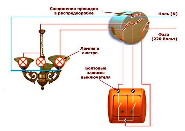
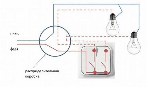
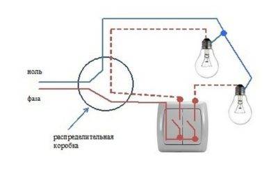
Two-gang switch and its connection, diagram and photo
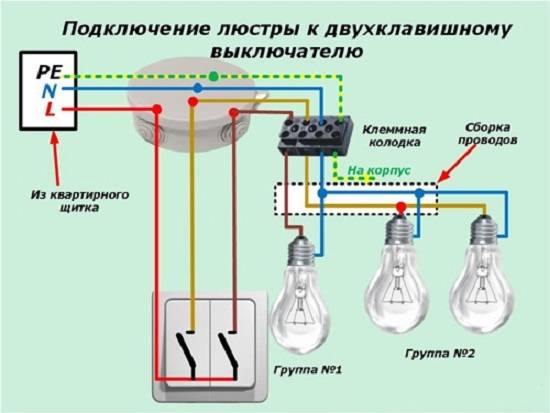
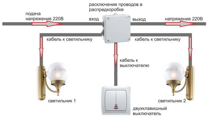
In a room with several lighting fixtures or with a chandelier for several light bulbs, you simply cannot do without a two-gang switch that allows you to adjust the level of lighting in a certain way: one or more light bulbs can be connected to each key. We will consider the connection diagrams of two-gang switches for two or more light bulbs.
In addition, this is a more compact solution than installing several conventional switches.By pressing one key, we turn on one light bulb (lamp) or a conditioned group of light bulbs (lamps); the second key is "responsible" for other lamps or fixtures; pressing both buttons turns on all lighting. As you can see, everything is simple.
However, the installation of a double switch can cause quite understandable difficulty. More precisely, its connection to the network. Therefore, now we will analyze the whole process in more detail.
The principle of operation of a switch with two keys is simple: a phase wire that is energized is connected alternately or simultaneously to both wires leading to consumers of electricity by closing the terminals, providing the result described above. Prepared (bare to a sufficient length) ends of the wires are attached to the terminals using screws or special clamps.
Let's get started mounting the switch on 2 keys
Connection of electrical appliances, including switches, must be carried out in conditions of good daylight and always with a previously de-energized network.
We draw your attention: first, be sure to turn off the mains voltage!
In addition, the necessary tools - Phillips and flat screwdrivers, pliers - must be with insulated handles. You will also need a sharp knife and good quality electrical tape.
First you need to draw a wiring and connection diagram and lay the wiring, after which you can take on the switches themselves. 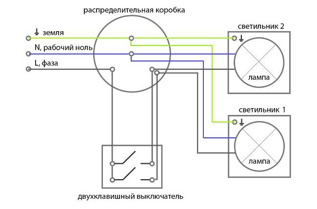
Wiring is laid in an open way (over the wall) in special corrugated pipes or in a closed way (internal wiring) in grooves specially made in the wall, which are then plastered. Wire connections are made in special junction boxes.
Three wires should go directly to the switch:
- one incoming, phase, which is energized - it is determined using a special probe screwdriver, for which you need to turn on the electricity, and after the phase wire is determined and marked in a convenient way, the network needs to be de-energized again;
- two outgoing leads to consumers (lamp holders in lamps). 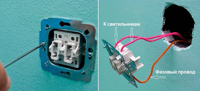
Connection
Strip the ends of the wires well from the insulation, by about 1 cm. If the wires are stranded, press the bare part with a special crimp.


Carefully inspect the terminal block: the input terminal near the hole where the wire is inserted is marked either with an arrow or with the Latin letter “L”. If the input terminal is marked with a letter, then the output terminal, in turn, is marked with arrows.
Connect the output wires to the appropriate terminals - as a rule, the end of the wire inserted into the hole is pressed with a screw using a screwdriver. At this stage, you can decide which lamps (light bulbs) will be turned on / off with which key by connecting the corresponding wires to the right and left terminals. 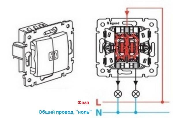
Then, in the same way, we connect the phase wire to the inlet and insert the switch into place in a special socket box, evenly tightening the right and left screws of the side stops. Then we put the keys in place and check the operation of the assembled circuit.
Illuminated two-gang switch
Two-key switches with dimmers (backlight) are very convenient for searching in a dark room, especially if the switch is located not immediately near the door, but elsewhere in the room.In order for the backlight to turn off, it is enough to connect one of the two wires leading from the indicators mounted in the keys on top to the phase contact, and going from below to one of the contacts that go to the consumers. As you can see, there is nothing complicated in this matter either.
By following our instructions and with the utmost care, you can connect several lighting fixtures and other electrical devices through a two-gang switch.
Options and Selection Tips
Before connecting a two-gang light switch, it would not be superfluous to familiarize yourself with the main characteristics of this switching device. In the modern market of electrical goods, their choice is so huge that you can get confused.
Any model is created for a certain amount of operating current, as a rule, these are 4A, 6A and 10A. If you need to connect a chandelier with a large number of lamps, for reliability it is better to choose a device with a rated operating current of 10A.
To connect the switching device to the mains, wires with a cross section of 1.5 to 2.5 mm2 are usually used. In most switches, wires are connected to its terminals using screw clamps. Now there are more modern models with spring-loaded terminal blocks, in which the installation of the wire is much easier, just insert the stripped tip into the clamping device. We advise you to opt for this option when buying switches.
You can ask the seller what mechanism the keys work on - cam or rocking.And also what the base of the switch is made of, it can be metal or ceramic, the second option is preferable and safer due to the low thermal conductivity of ceramics.
Now it is easy to choose a model that is suitable for your interior, the market offers a huge selection of switches in any color.
When buying, be sure to click the keys, they should work clearly, be well fixed, and make a characteristic click when turned on / off.
Modern models are often made with backlight. This is very convenient, you can safely opt for this option. In the dark, entering the room, you can easily determine the location of the device by the luminous elements.
Choosing a switch from the point of view of an interior designer (video):
Advice! Try to buy switches and materials for connecting it in electrical stores. There is not only a huge selection, but also sales consultants who can explain all the parameters, characteristics and technical capabilities of the selected model.
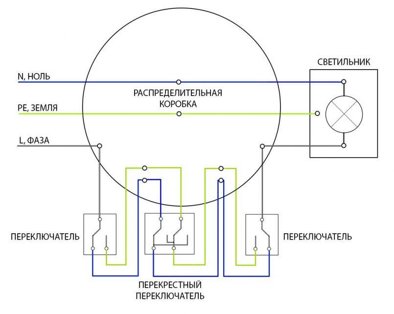
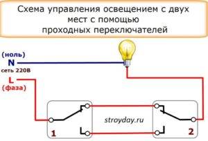
Scheme of using two pass-through switches
With the help of walk-through switches, independent lighting control from several selected points is organized. This method is considered the most practical, contributing to the reduction of energy consumption. Passage switches are usually used in large private houses, long corridors, flights of stairs and platforms. These devices are inherently switches, since contacts are transferred from one to another during operation.
In order to connect devices from two selected points, a three-core cable must be laid to the connection point in advance, two switches and one junction box must be purchased. In the simplest scheme, the neutral wire is brought from the shield to the junction box, where it is connected to the zero going to the lamp.
The switches are connected to each other using a three-core cable passed through the box. A single-core wire is used to connect the phase to the switches and from them to the lamp. If more than two control devices are connected, the number of cores in the cable increases according to the number of switches. Despite the ease of installation, you need to carefully monitor the sequence of connecting wires to a double pass switch.
The principle of operation of the pass switch
On the key of the pass-through switch there are two arrows (not large), directed up and down.
This type has a one-button switch. There may be double arrows on the key.
The connection diagram is not much more complicated than the connection diagram of a classic switch. The difference is only in a larger number of contacts: a conventional switch has two contacts, and a pass-through switch has three contacts. Two out of three contacts are considered common. In the lighting switching circuit, two or more similar switches are used.
Differences - in the number of contacts
The switch works as follows: when switching with the key, the input is connected to one of the outputs. In other words, the feed-through switch is designed for two operating states:
- Input connected to output 1;
- Input connected to output 2.
It has no intermediate positions, therefore, the circuit works as it should. Since there is a simple connection of contacts, according to many experts, they should have been called "switches". Therefore, the transitional switch can be safely attributed to such devices.


In order not to be mistaken what kind of switch, you should familiarize yourself with the switching circuit, which is present on the switch body. Basically, the circuit is available on branded products, but you will not see it on inexpensive, primitive models. As a rule, the circuit can be found on switches from Lezard, Legrand, Viko, etc. As for cheap Chinese switches, there is basically no such circuit, so you have to call the ends with the device.
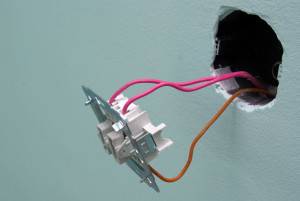
This is the switch on the back.
As mentioned above, in the absence of a circuit, it is better to call contacts at different key positions. This is also necessary in order not to mix up the ends, since irresponsible manufacturers often confuse the terminals during the production process, which means that it will not work correctly.
To ring the contacts, you must have either a digital or pointer device. The digital device should be switched to dialing mode with the switch. In this mode, short-circuited sections of electrical wiring or other radio components are determined. When the ends of the probes are closed, the device emits a sound signal, which is very convenient, since there is no need to look at the device display. If there is a pointer device, then when the ends of the probes are closed, the arrow deviates to the right until it stops.
In this case, it is important to find a common wire.For those who have the skills to work with the device, there will be no particular problems, but for those who picked up the device for the first time, the task may not be solvable, despite the fact that you need to figure out only three contacts
In this case, it is better to first watch the video, which clearly explains, and most importantly shows how to do it.
Pass-through switch - how to find a common terminal?
Watch this video on YouTube
Preparatory work
When working with an electrician, extreme accuracy and caution must be observed, therefore, all materials and tools needed for work must be prepared and purchased in advance:
- screwdriver flat and Phillips;
- pliers;
- side cutters;
- insulating tape;
- a good construction knife with a sharp blade (for stripping the ends of wires);
- for crimping, it is more convenient to use a special tool - a crimping tool (it is not required if the wires are not stranded);
- switch;
- wires.
Switch connection tools
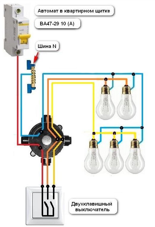
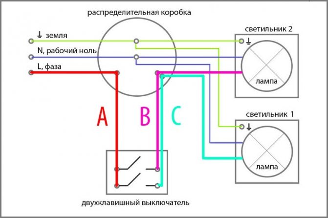
It is extremely important to draw a diagram for connection and lay the wiring in advance and correctly. Wiring diagram for a two-button switch
Wiring diagram for a two-button switch
The circuit should include the following three wires:
- Ground wire (output to the light source, indicated on the diagram as "0" or with an arrow pointing down).
- Neutral wire (also output to the light source, denoted by the letter "N").
- Phase - a wire that is energized, which, when turned on, must provide light bulbs with power (terminals for a phase wire are indicated by the Latin letter "L").
Wire connection sequence
Carry out the wiring in one of two possible ways: open or closed. For the first, additional materials will be needed - corrugated pipes or strobes, for the second - you need to hollow out grooves in the walls.
Please note that wiring is done before plastering the walls and ceiling. To install a socket under the switch, you will have to hollow out a recess in the wall, you can use a chisel and a hammer, but it is better to use a puncher with a special crown
To install a socket under the switch, you will have to gouge a recess in the wall, you can use a chisel and a hammer, but it is better to use a puncher with a special crown.
How to connect a pass-through switch, read here.
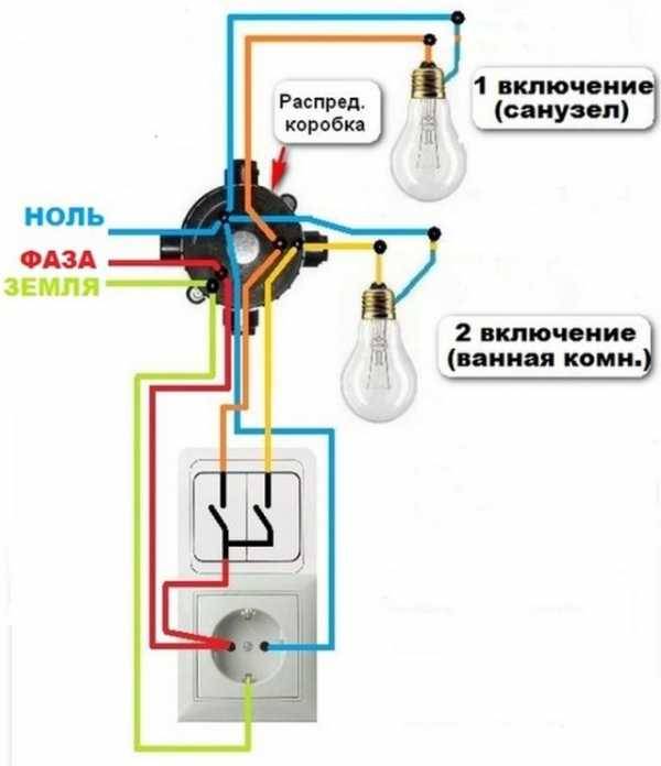
Connection via socket
If there is an outlet near the planned installation site for turning off the light, then you can power the phase and zero from it.
In order for the connection of the switch from the outlet to be successful, you must follow the following sequence of actions:
Initially, you need to remove the power supply from the outlet. Similar actions can be performed by relieving stress from the whole house.


You need to open the outlet and check the voltage.
A wire is connected to the socket phase, the second side of which is attached to the input of the switch. A wire directly connected to the lamp is attached to the output of the unit to turn off the light.
A wire is attached to the zero contact of the socket, the second end of which is connected to the output of the lamp. In the same way, the protective wire is connected, only to the corresponding contact of the lamp.
Illuminated switches have begun to be especially popular at this stage of time; when installing them, it is advisable to turn to a professional, since improper connection of such switches can refuse an increased load on the wiring, as a result of which it will undergo combustion.
In the absence of basic skills in electrics, it is worth refusing even to independently install switches containing one key.
Some photos of the switch can be found below.


