- System description
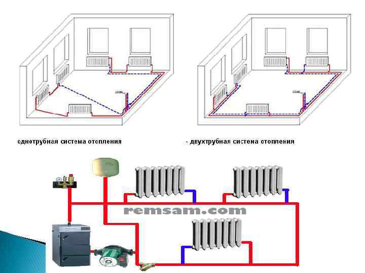
- Single pipe horizontal
- Advantages and disadvantages of the scheme
- Features of the installation of a single-pipe horizontal system
- Automatic make-up
- The device and principle of distribution of the coolant
- How to calculate pipe diameter
- Beam wiring connection diagram
- Preparatory work
- System installation
- Main structural elements
- Selection and installation of a circular pump
- The choice and role of the distribution manifold
- Principle of operation and types of node control
System description
There are many opinions about the origin of the name of the Leningradka heating system. Some believe that the system was first used by the Leningrad construction organizations. However, due to the ease of installation, it could well be used in any region. Others say that technical regulations for the system were developed in this city, which subsequently became used throughout the country. In any case, during the mass construction of barrack-type houses and social buildings, the Leningradka system was very popular. This was explained by the low cost of the system and the ease of its installation.
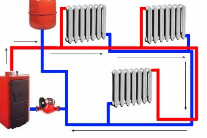
Scheme of the Leningradka heating system in a private house is a looped system on which heat exchangers are installed in series.As a result, hot water moves from the boiler or central heating input and passes through all the batteries. However, with distance from the boiler, the coolant cools down, as a result, the first radiators heat up more than those located at the end of the line. The last batteries are especially deprived of thermal energy.
In such systems, the coolant can move naturally or with the use of a pump, without much effect on the location of the radiators.
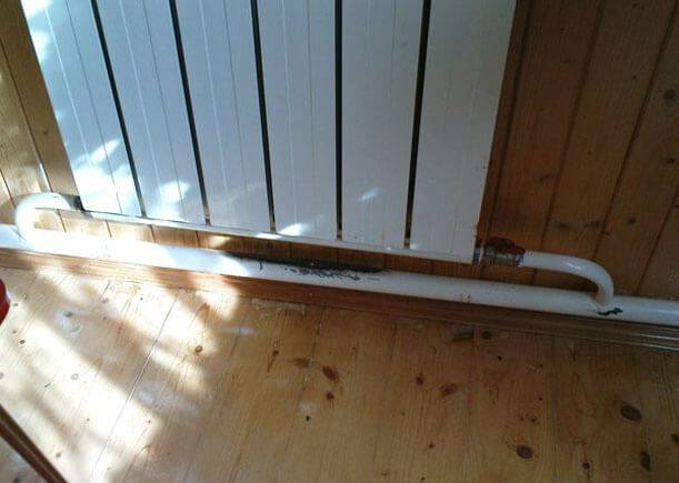
The Leningradka single-pipe heating system with natural circulation is the best option for one-story buildings, where radiators are placed on the same level. In addition, the Leningrad heating system involves the passage of the main pipe, which closes the heating system circuit, close enough to the floor. In this case, it becomes possible to hide it as much as possible under the floor covering.
At arrangement of heating according to the system scheme heating Leningradka in multi-storey buildings, an additional installation of a circulation pump is required, since it is almost impossible to raise the coolant to a great height in a natural way. In this case, it will be necessary to install a high-capacity boiler and perform accurate calculations of the vertical and horizontal sections of the system. However, this option will call into question the profitability of operating the system. In other words, installing a circulation pump will require additional costs, but it will save you unnecessary problems and hassle.
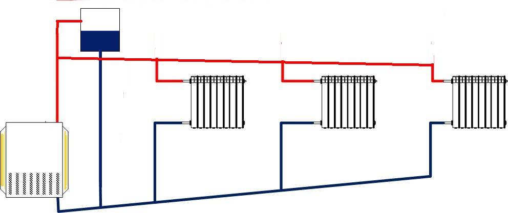
Single pipe horizontal
The easiest option one-pipe horizontal system heating with bottom connection.
When creating a heating system for a private house with your own hands, a single-pipe wiring scheme can be the most profitable and cheapest. It is equally well suited for both single-story houses and two-story houses. In the case of a one-story house, it looks very simple - the radiators are connected in series - in order to ensure the consistent flow of the coolant. After the last radiator, the coolant is sent through a solid return pipe to the boiler.
Advantages and disadvantages of the scheme
To begin with, we will consider the main advantages of the scheme:
- ease of implementation;
- great option for small houses;
- saving materials.
A single-pipe horizontal heating scheme is an excellent option for small rooms with a minimum number of rooms.
The scheme is really very simple and understandable, so even a beginner can handle its implementation. It provides for a serial connection of all installed radiators. This is an ideal heating layout for a small private house. For example, if this is a one-room or two-room house, then “fencing” a more complex two-pipe system does not make much sense.
Looking at the photo of such a scheme, we can note that the return pipe here is solid, it does not pass through the radiators. Therefore, such a scheme is more economical in terms of material consumption. If you do not have extra money, such a wiring will be the most optimal for you - it will save money and allow you to provide the house with heat.
As for the shortcomings, they are few. The main disadvantage is that the last battery in the house will be colder than the very first one.This is due to the sequential passage of the coolant through the batteries, where it gives off the accumulated heat to the atmosphere. Another disadvantage of a single-pipe horizontal circuit is that if one battery fails, the entire system will have to be turned off at once.


Despite certain disadvantages, this heating scheme continues to be used in many private houses of a small area.
Features of the installation of a single-pipe horizontal system
Creating water heating of a private house with your own hands, a scheme with a single-pipe horizontal wiring will be the easiest to implement. During the installation process, it is necessary to mount the radiators, and then connect them with pipe sections. After connecting the last radiator, it is necessary to turn the system in the opposite direction - it is desirable that the outlet pipe runs along the opposite wall.
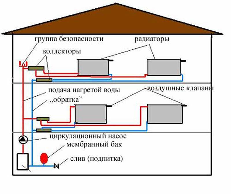
A single-pipe horizontal heating scheme can also be used in two-story houses, each floor is connected in parallel here.
The larger your home, the more windows it has and the more radiators it has. Accordingly, heat losses also increase, as a result of which it becomes noticeably cooler in the last rooms. You can compensate for the drop in temperature by increasing the number of sections on the last radiators. But it is best to mount a system with bypasses or with forced circulation of the coolant - we will talk about this a little later.
A similar heating scheme can be used to heat two-story houses. To do this, two chains of radiators are created (on the first and second floors), which are connected in parallel to each other.There is only one return pipe in this battery connection scheme; it starts from the last radiator on the first floor. A return pipe is also connected there, descending from the second floor.
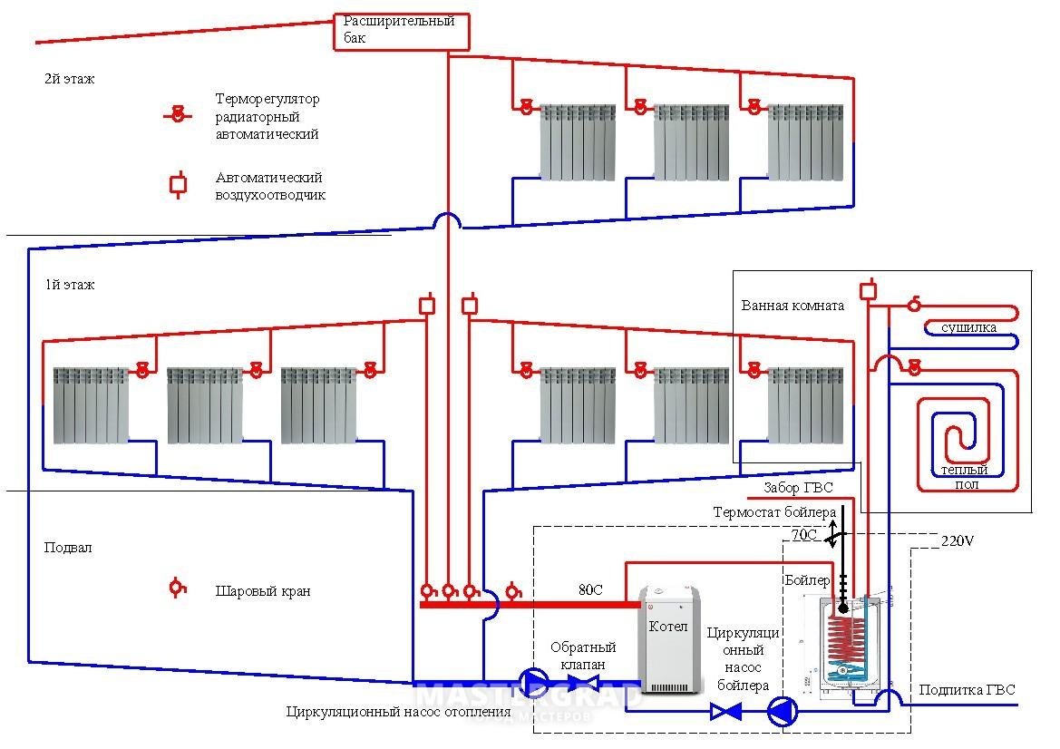
Automatic make-up
For a heating system with a closed circuit, it is most advisable to equip an automatic make-up unit. Despite its high cost, the use of such equipment is economically justified. Solid fuel boilers, which are used in closed heating systems, have high performance. A decrease in the coolant level can lead to a critical overheating of the heat exchanger, furnace and the boiler itself. In this case, the intensive movement of the coolant along the circuit can lead to a rapid decrease in its amount. And the absence of a safety device directly on the boiler will not make it possible to quickly monitor the amount of water in pipelines and radiators.
For the device of the automatic feeding unit, various types are used devices and valves. It is most expedient to purchase a specialized device - a make-up reducer. It combines in one case all the necessary functional elements:
- check valve;
- Filter;
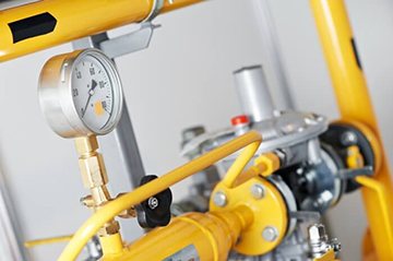
- Manometer with valve;
- Pressure control device.
On the gearbox cover there is a screw that controls the operating pressure of the device. It is recommended to set it to two bars - the optimal pressure in an autonomous closed heating system.
An autonomous system of automatic feeding is one of the most complex, technically and expensive.Its use is economically justified for servicing large heating systems for several cottages using solid fuel boilers. Such a system, most often, has a commercial application, and is installed at tourist sites, ski resorts and recreation centers, remote from centralized infrastructures. It consists of the following elements:
- Water tank with a volume of 50-100 l;
- Submersible pump;
- Pressure switch;
- Suction hose;
- Air valve;
- Level sensor;
- Fitting with a coarse filter;
- Liquid level sensor.
If not water is used as a heat carrier, but glycol-containing solutions, the system is additionally equipped with a mixing device to prevent the heat carrier from separating into different density fractions.
The principle of operation of the automatic heating make-up system for large thermal units is as follows:
- The coolant is fed into the container through a fitting with a filter. This will eliminate the possibility of contamination entering the heating pipelines;
- A volumetric pump with limited capacity is used to fill the heating system. This will make it possible to evenly fill pipelines and heat engineering devices with coolant at the first start-up;
- When the set pressure is reached, the relay turns off the pump and stops the supply of coolant. When the operating pressure decreases, the relay automatically switches on the pump;
- The signal from the liquid level sensor located in the tank is connected to the light alarm in an open circuit;
- The air valve is installed in the lid of the tank to equalize the pressure during the selection of the coolant;
- All volatile control devices are connected via an uninterruptible power supply, which will ensure constant control of the coolant pressure in the heating system.
The simplest situation is with gas boilers that are used in autonomous heating systems for apartments. Almost all modern models, especially double-circuit gas boilers, already have a built-in make-up gearbox. It connects to the DHW supply pipe. And when the pressure drops, it automatically adds coolant to the pipeline. The installation wizard does not need to perform special operations and additional connections. All necessary controls and controls are already included as standard.
Read also:
The device and principle of distribution of the coolant
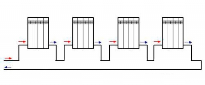
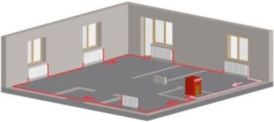
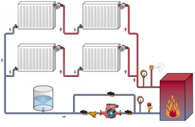
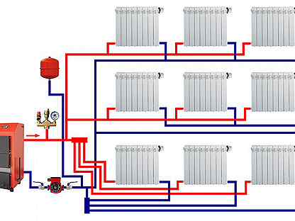
The system is called single-pipe, since heated water is supplied to and leaves the heating radiators through a single collector. The pipeline is common to all batteries connected to the main branch. That is, the input and output connections of each heater are connected to one pipe, as shown in the example of a one-story building heat supply scheme.
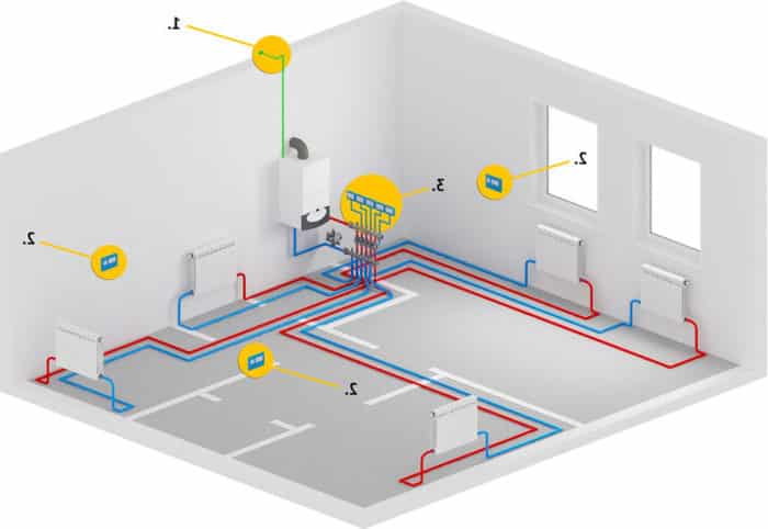


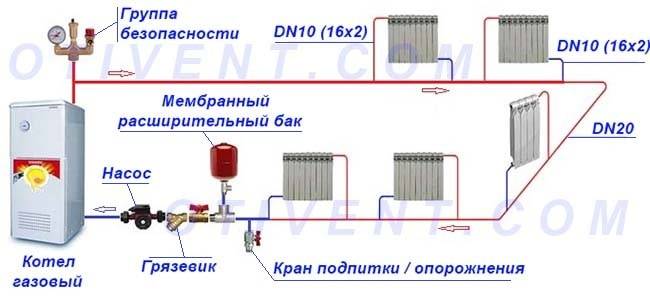
The classic version of a closed circuit with forced movement of the coolant connected to a gas boiler
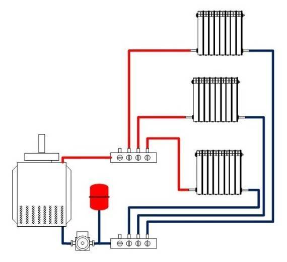
How does a single-pipe radiator heating system work:
- The heated coolant coming from the boiler reaches the first battery and is divided by a tee into two unequal flows. The bulk of the water continues to move straight along the line, a smaller part flows into the radiator (about 1/3).
- Having given off heat to the walls of the battery and cooled by 10-15 ° C (depending on the power and the actual return of the radiator), a small flow through the outlet pipe returns to the common collector.
- Mixing with the main flow, the cooled coolant reduces its temperature by 0.5–1.5 degrees. The mixed water is delivered to the next heater, where the cycle of heat exchange and cooling of the main stream is repeated.
- As a result, each subsequent battery receives a coolant with a lower temperature. At the end, the cooled water is sent back to the boiler along the same line.
The color and size of the arrows in the figure characterizes the temperature and the amount of water, respectively. First, the streams are separated, then mixed, cooling down by a couple of degrees
The lower the temperature of the circulating water, the less heat goes to the last heaters. The problem is solved in three ways:
- at the end of the highway, batteries of increased power are installed - the number of sections is increased or the area of panel steel radiators is increased;
- by increasing the pipe diameter and pump performance, the coolant flow through the main manifold increases;
- a combination of the two previous options.
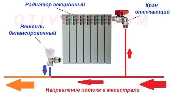
Connecting radiators to a single distribution line is the main difference between single-pipe wiring and other two-pipe systems, where the supply and return of the coolant is organized in two separate branches.
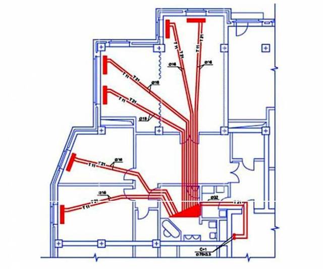
How to calculate pipe diameter
When arranging dead-end and collector wiring in a country house with an area of up to 200 m², you can do without scrupulous calculations. Take the cross section of highways and piping according to the recommendations:
- to supply the coolant to radiators in a building of 100 square meters or less, a Du15 pipeline (outer dimension 20 mm) is sufficient;
- battery connections are made with a section of Du10 (outer diameter 15-16 mm);
- in a two-story house of 200 squares, the distributing riser is made with a diameter of Du20-25;
- if the number of radiators on the floor exceeds 5, divide the system into several branches extending from the Ø32 mm riser.
Gravity and ring system is developed according to engineering calculations. If you want to determine the cross-section of pipes yourself, first of all, calculate the heating load of each room, taking into account ventilation, then find out the required coolant flow rate using the formula:
- G is the mass flow rate of heated water in the section of the pipe supplying the radiators of a particular room (or group of rooms), kg/h;
- Q is the amount of heat required to heat a given room, W;
- Δt is the calculated temperature difference in the supply and return, take 20 °С.
Example. To warm up the second floor to a temperature of +21 °C, 6000 W of thermal energy is needed. The heating riser passing through the ceiling must bring 0.86 x 6000 / 20 = 258 kg / h of hot water from the boiler room.
Knowing the hourly consumption of the coolant, it is easy to calculate the cross section of the supply pipeline using the formula:
- S is the area of the desired pipe section, m²;
- V - hot water consumption by volume, m³ / h;
- ʋ – coolant flow rate, m/s.
Continuation of the example. The calculated flow rate of 258 kg / h is provided by the pump, we take the water velocity of 0.4 m / s. The cross-sectional area of the supply pipeline is 0.258 / (3600 x 0.4) = 0.00018 m². We recalculate the section into diameter according to the circle area formula, we get 0.02 m - DN20 pipe (outer - Ø25 mm).
Note that we neglected the difference in water densities at different temperatures and substituted the mass flow rate into the formula.The error is small, with a handicraft calculation it is quite acceptable.
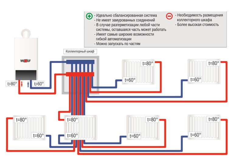
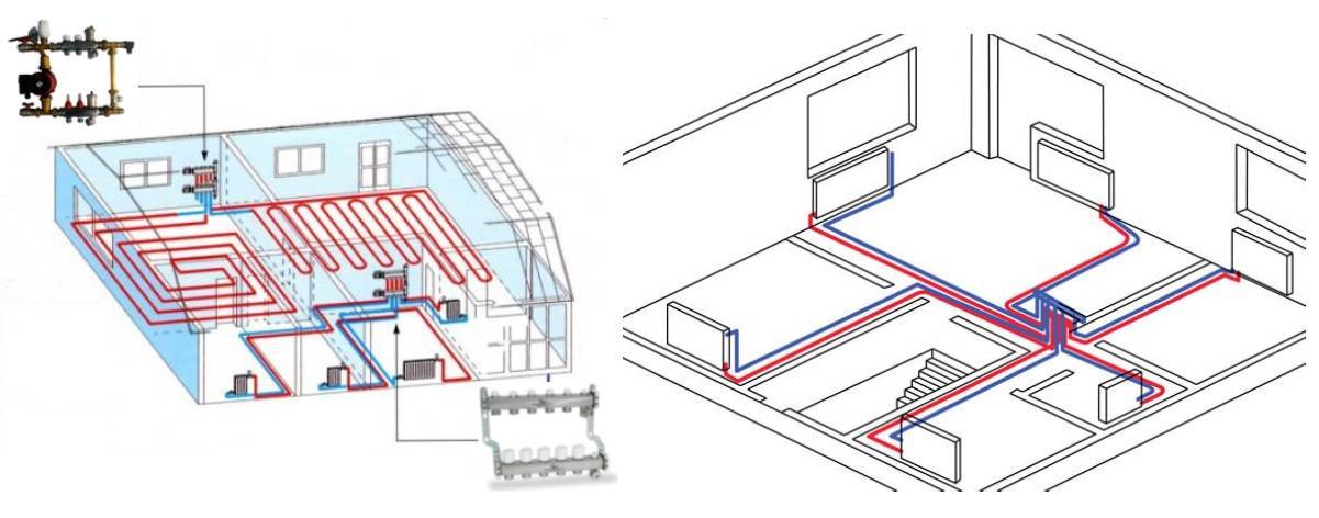
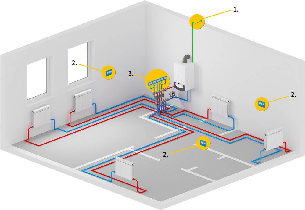
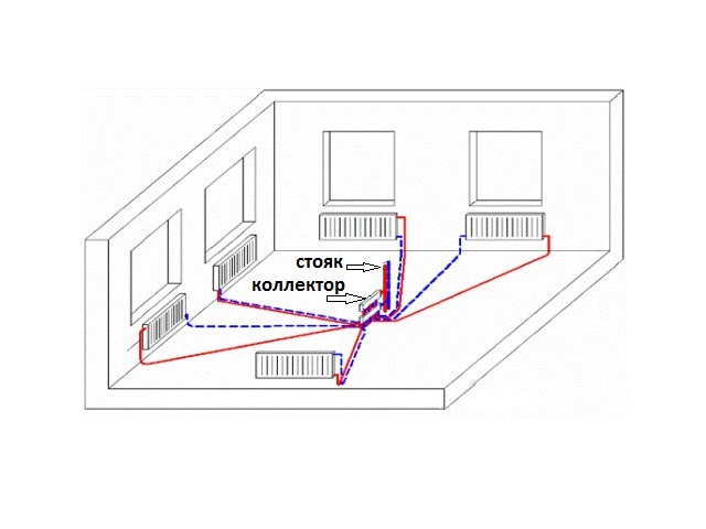
Beam wiring connection diagram
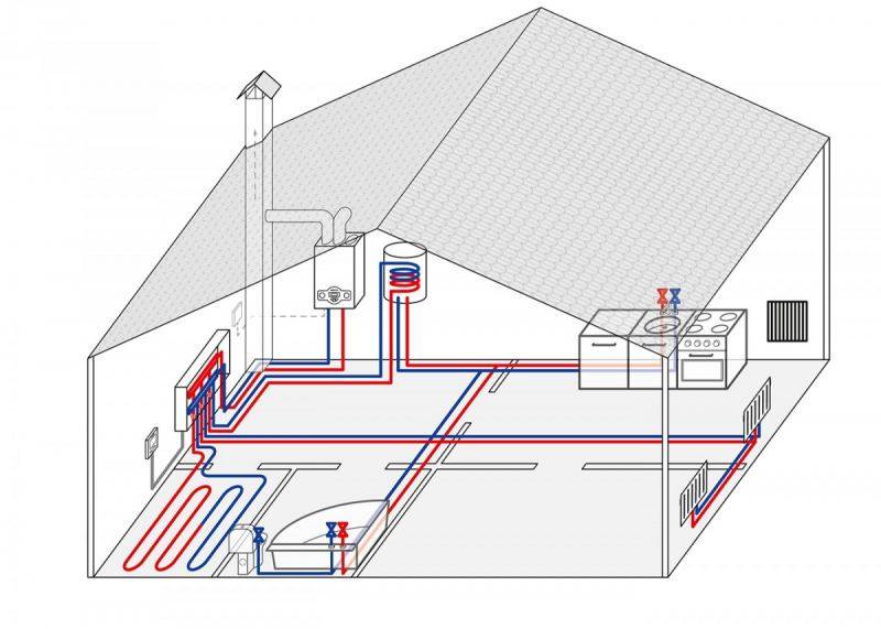
Pipelines, as a rule, are placed in a cement screed made on a subfloor. One end is connected to the corresponding collector, the other leads out of the floor under the corresponding radiator. A finishing floor is laid on top of the screed. When installing a radiant heating heating system in an apartment building, a vertical line is made in the channel. Each floor has its own pair of collectors. In some cases, if there is enough pump pressure and there are few consumers on the last floor, they are connected directly to the collectors of the first floor.
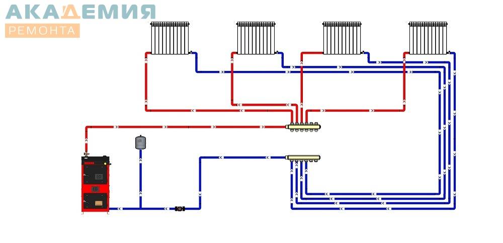
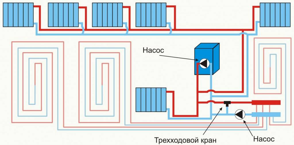
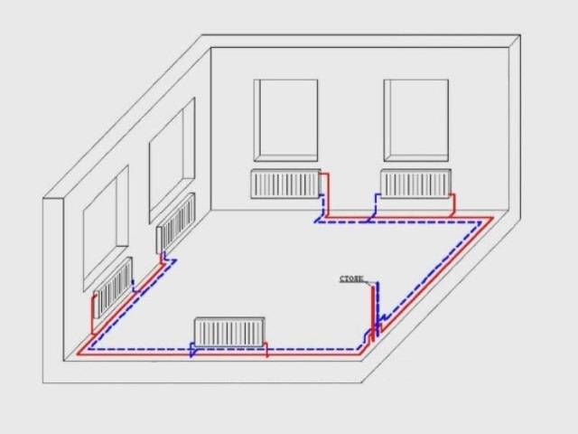
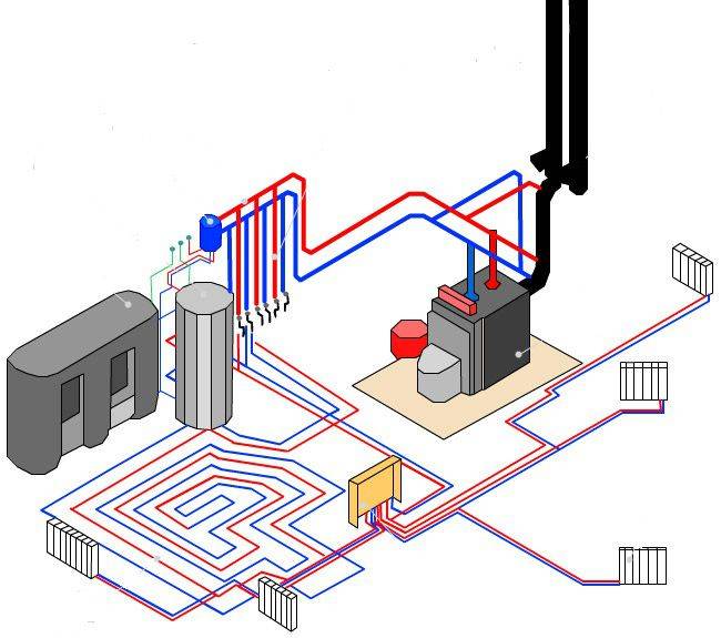

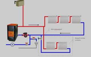
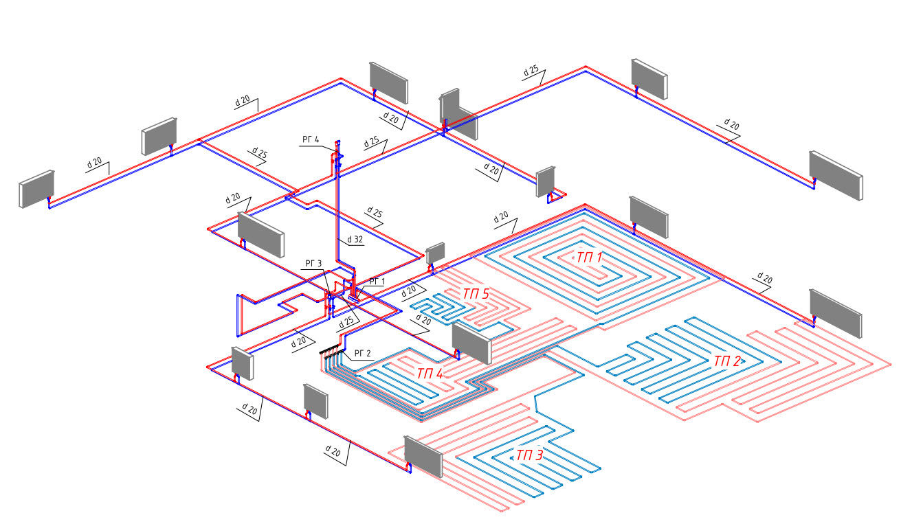
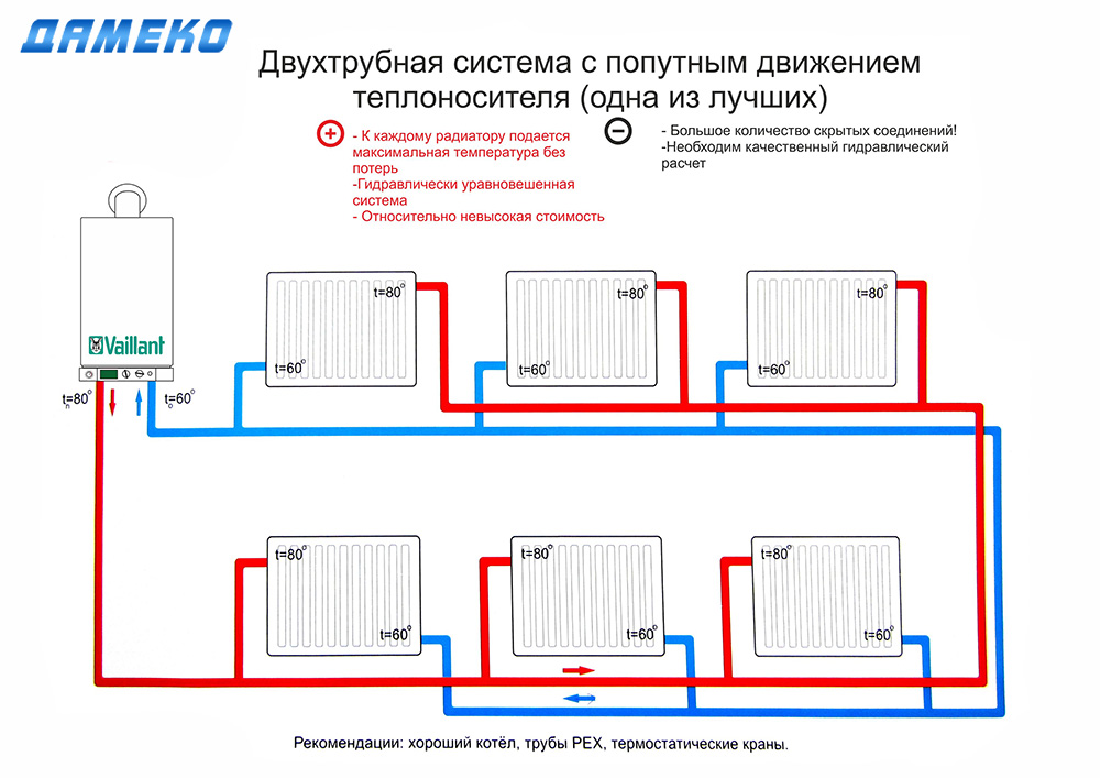
 Diagram of a radiant heating system
To effectively deal with traffic jams, air valves are placed on the manifold and at the end of each beam.
Preparatory work
During preparation for installation, the following work is performed:
- establish the location of radiators and other heat consumers (warm floors, heated towel rails, etc.);
- perform a thermal calculation of each room, taking into account its area, ceiling height, number and area of windows and doors;
- choose a model of radiators, taking into account the results of thermal calculations, the type of coolant, pressure in the system, calculate the height and number of sections;
- make the routing of direct and return pipelines from the collector to the radiators, taking into account the location of doorways, building structures and other elements.
There are two types of trace:
- rectangular-perpendicular, pipes are laid parallel to the walls;
- free, pipes are laid along the shortest route between the door and the radiator.
The first type has a beautiful, aesthetic appearance, but requires significantly more pipe consumption.All this beauty will be covered with a finishing floor and floor covering. Therefore, owners often choose free tracing.
It is convenient to use free computer programs for tracing pipes, they will help you complete the tracing, allow you to accurately determine the length of the pipes and draw up a statement for the purchase of fittings.
System installation
Laying the beam system on the subfloor will require a number of measures aimed at reducing transport heat losses and preventing freezing if water was chosen as the heat carrier.
Between the draft and finishing floor, a distance sufficient for thermal insulation should be provided.
If the subfloor is a concrete floor (or foundation slab), then a layer of heat-insulating material will need to be laid on it.
For ray tracing, metal-plastic or polyethylene pipes are used, which have sufficient flexibility. For radiators with a thermal power of up to 1500 watts, 16 mm pipes are used, for more powerful ones, the diameter is increased to 20 mm.
They are laid in corrugated sleeves, which provide additional thermal insulation and the necessary space for thermal deformations. After a meter and a half, the sleeve is fastened with screeds or clamps to the subfloor to prevent its displacement during the cement screed.
Next, a layer of heat-insulating material with a thickness of at least 5 cm is mounted, made of dense basalt wool, polystyrene foam or expanded polystyrene. This layer must also be fixed to the subfloor with dish-shaped dowels. Now you can pour the screed. If the wiring is carried out on the second floor or higher, it is not necessary to lay thermal insulation.
It is important to remember that no joints should remain under the flooded floor. If there are few consumers on the second, attic floor, and the pressure created by the circulation pump is sufficient, then a scheme with one pair of collectors is often used
Pipes to consumers on the second floor extend pipes from the collectors from the first floor. The pipes are assembled into a bundle and carried along a vertical channel to the second floor, where they are bent at a right angle and lead to the consumer accommodation points.
If there are few consumers on the second, attic floor, and the pressure created by the circulation pump is sufficient, then a scheme with one pair of collectors is often used. Pipes to consumers on the second floor extend pipes from the collectors from the first floor. The pipes are assembled into a bundle and carried along a vertical channel to the second floor, where they are bent at a right angle and lead to the points where consumers are located.


It is important to remember that when bending, the minimum bending radius for a given tube diameter must be observed. It can be viewed on the manufacturer's website, and for bending it is better to use a manual pipe bender
Sufficient space must be provided at the outlet of the vertical channel to accommodate the rounded section.
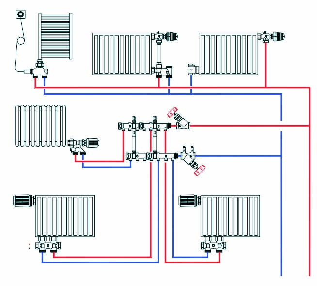
Main structural elements
The most important component of the beam wiring are collectors. When designing a radiant heating system for a two-story (or multi-story) house, a collector cabinet will need to be placed on each floor. Collectors and control valves (manual or automated) are mounted in cabinets, where they are easily accessible during operation and periodic or emergency maintenance.
A small number of connections compared to a tee wiring ensures greater hydrodynamic stability of the entire heating system.
The second component is the circulation pump, it provides the creation of pressure in the system for supplying the heated coolant through pipes to the radiators and collecting the return.
Selection and installation of a circular pump
For a radiant heating system, the option of lower supply of hot liquid to radiators is most often chosen. To ensure its forced circulation, a circulation pump is used. Its power should be enough to provide a pressure that allows the coolant to reach the most remote heat exchangers, including underfloor heating.
Forced circulation accelerates the circulation of the coolant through the rings of the system. This reduces the difference between the incoming and outgoing temperature of the heating circuit. Such an increase in heating efficiency allows either to reduce the capacity of the boiler, or to have more power in case of extreme weather.
When selecting a device, two main parameters are taken into account that determine its power and speed:
- productivity, cubic meters per hour;
- head, in meters;
- noise level.
 When choosing a circular pump, consider the performance and pressure
For correct selection, it will be necessary to take into account the diameter and total length of the distribution pipes, the maximum height difference in relation to the height of the pump installation. When carrying out engineering and plumbing calculations, special tables offered by manufacturers are used.
Experts recommend adhering to the following rules for installing the pump:
- devices with a wet rotor are mounted so that the shaft is horizontal;
- devices with a built-in thermostat are mounted closer than 70 cm from the heating boiler in order to avoid erroneous operation;
- the circulation pump is mounted on the return section of the pipeline system, since its temperature is lower and the device will last longer;
- modern heat-resistant pumps can also be placed on the supply line;
- the heating circuit should be equipped with a device for releasing air pockets, it can be replaced by a pump with a built-in air valve;
- the device should be placed as close as possible to the expansion tank;
- Before installing the pump, the system is flushed from mechanical impurities.
If the electrical network parameters at the installation site are not stable, it is recommended to connect the pump and the boiler control system through a voltage stabilizer of sufficient power. If power outages are frequent, an uninterruptible power supply device should be provided - either battery-operated or with an automatically started electric generator.
Often, when optimizing the cost of a system, there is a temptation to do without a circulation pump. This option, in principle, is acceptable for one-story buildings of a small area. This will reduce the heating efficiency. When using natural circulation, pipes with a larger cross section should be used. In addition, the expansion tank should be placed at the highest point of the building.


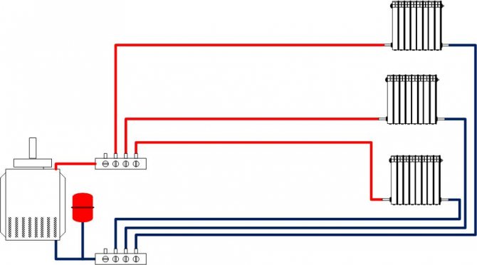


The choice and role of the distribution manifold
This most important element of the system distributes the flow of hot coolant supplied by the boiler to individual distribution beams. The second collector collects the liquid that gave up its heat and returns it to the heat exchanger for subsequent heating.The return valve can bypass part of the return flow to the main circuit if it is required to lower the temperature of the coolant without changing the boiler operation mode.
There are collectors on the market that support from 2 to 18 beams. Collectors are equipped with shut-off or control valves, or automatic thermostatic valves. With their help, the required temperature regime for each beam is set.
Principle of operation and types of node control
The most important task of the make-up unit is the ability to supplement the missing part of the heat carrier in the heating system, which will normalize the operating pressure indicators.
To date, a couple of options for replenishing the volume of lost heat carrier are practiced:
- Manual control is most convenient when servicing a small heating system, in which it is possible to independently control the pressure level in strict accordance with the pressure gauge. In this case, the flow of the heat carrier occurs by gravity or with the help of make-up pumping equipment.
- The automatic make-up mode automatically turns on when the pressure level inside the system drops below the set limits. In this case, the valve is activated to feed the heating system and the flow hole is opened with the forced flow of the heat carrier. After equalizing the pressure indicators, the valve closes, and the standard shutdown of the pumping equipment is also performed.
Despite the convenience of the second option, it is very important to remember that the automatic make-up mode implies the mandatory inclusion of an additional element in the system that needs electrical supply. In case of frequent power outages, it is advisable to duplicate the athematic control of the manual feed lever
The simplest gravity installation in the manual version carries out the usual set of tap water until the excess exits the overflow pipe on the expansion tank, and the advantage of automation is the almost complete absence of the need to control the process of feeding the system.