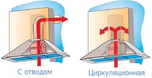
- How to determine the cause in each case?
- Design features
- Compressor pressure regulation
- What to do if there is a leak in an apartment or a private house?
- Disassembly of the membrane if it drips from the adjustment hole
- Elimination of leaks in the piston
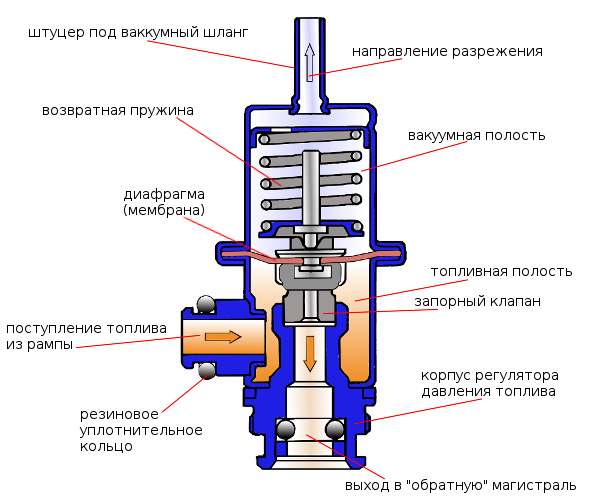
- Principle of operation
- Why you need to monitor the pressure in the boiler
- Causes of pressure increase in case of boiler damage
- Automatic make-up unit
- When do you need to adjust and remove the default settings?
- System Diagnostics
- Prevention of the problem
- Kinds
- Piston
- Membrane
- Flowing
- Wiring diagram
- flanges
- Relay installation
- Relay adjustment
- Causes of pressure drop
- Why does pressure drop occur in the accumulator
How to determine the cause in each case?
Diagnosing a leak is elementary - everyone can handle it. It is based on knowledge of the principle of operation of the regulating pressure gauge, while it does not depend on the type of construction.
Labyrinth types are not considered, since they do not have any mechanisms. Also, electronic and automatic samples are not considered, which are structurally more complex and competent maintenance can only be carried out by specialists.
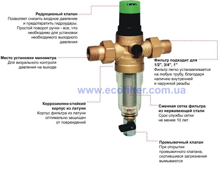
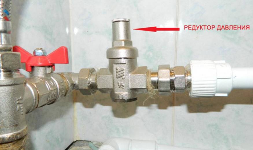
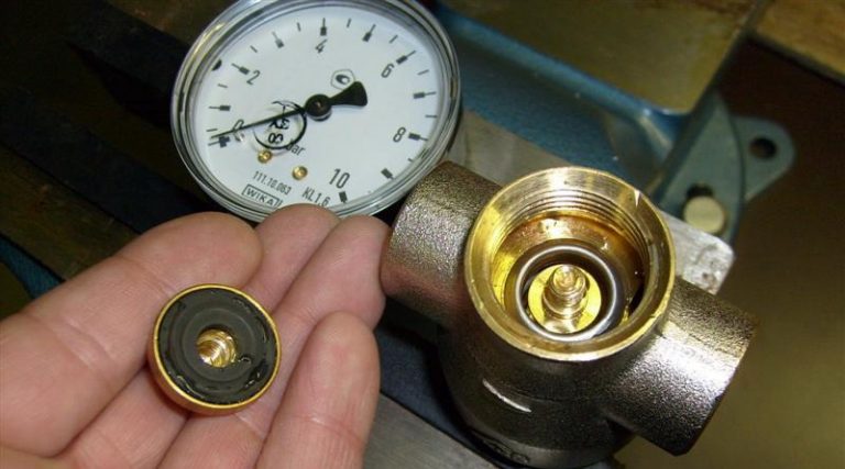
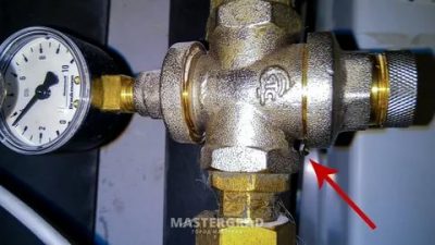
In addition to the inlet and outlet pipes, the regulator has two more holes.Through one, access is made to adjusting the force of the spring on the piston or diaphragm, and the other is designed to connect a pressure gauge - a pressure sensor may not be provided, then the hole is equipped with a plug with a sealing ring. Leaks can only occur in these places.
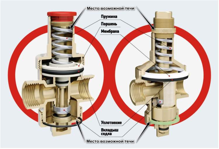
If water leaks from under the plug (where the pressure gauge is connected), then this means that the sealing gasket has become unusable. Cavitation (corrosion) destruction of the plug thread is also possible. The internal mechanism is fine.
If it leaks from under the adjustment hole, this means that the sealing of the working compartment is broken. The large piston o-ring is worn out and needs to be replaced. The spring is in water, its corrosive destruction is possible.
In a membrane gearbox, these signs can indicate both a violation of the position of the membrane (loose fit to the grooves of the working chamber) and its rupture. One way or another, to eliminate the defect and conduct a complete revision, the gearbox must be completely disassembled.
Design features
The main tasks that water flow control sensors, installed in domestic pipelines, are to turn off the pumping equipment at the moment when there is no liquid in the system or the pressure of its flow exceeds the standard value, and turn it on again when the pressure drops. The effective solution of these important tasks is ensured by the design of the sensor, which is formed by the following elements:
- a branch pipe through which water enters the sensor;
- a membrane constituting one of the walls of the inner chamber of the sensor;
- reed switch providing closing and opening of the pump power supply circuit;
- two springs of different diameters (the degree of their compression regulates the pressure of the fluid flow at which the water flow switch for the pump will operate).
Main components of an industrial flow sensor
The device of the above design works as follows:
- Entering the inner chamber of the sensor, the water flow exerts pressure on the membrane, displacing it.
- The magnetic element fixed on the reverse side of the membrane, when it is displaced, approaches the reed switch, which leads to the closure of its contacts and turning on the pump.
- If the pressure of the water flow passing through the sensor drops, then the membrane returns to its original position, the magnet moves away from the switch, its contacts open, respectively, the pumping unit is turned off.
The principle of operation of the flow sensor, built on the basis of a permanent magnet and a reed switch
In pipeline systems for various purposes, sensors that control the flow of water are installed quite simply.
The main thing is to choose the right device, paying attention to its operating parameters and characteristics of pumping equipment.
Compressor pressure regulation
As mentioned above, after creating a certain level of air compression in the receiver, the pressure switch turns off the engine of the unit. Conversely, when the pressure drops to the switch-on limit, the relay starts the engine again.
But often situations that arise make you change the factory settings of the pressure switch and adjust the pressure in the compressor at your discretion. Only the lower turn-on threshold will be changed, since after changing the upper turn-off threshold upwards, the air will be discharged by the safety valve.
The pressure in the compressor is adjusted as follows.
- Turn on the unit and record the pressure gauge reading at which the engine turns on and off.
- Be sure to disconnect the device from the mains and remove the cover from the pressure switch.
- After removing the cover, you will see 2 bolts with springs. The large bolt is often denoted by the letter "P" with the signs "-" and "+" and is responsible for the upper pressure, at which the device will be turned off. To increase the air compression level, turn the regulator towards the “+” sign, and to decrease it, towards the “-” sign. First, it is recommended to make half a turn of the screw in the desired direction, then turn on the compressor and check the degree of pressure increase or decrease using a pressure gauge. Fix at what indicators of the device the engine will turn off.
- With a small screw, you can adjust the difference between the on and off thresholds. As mentioned above, it is not recommended that this interval exceed 2 bars. The longer the interval, the less often the machine's engine will start. In addition, there will be a significant pressure drop in the system. Setting the difference between the on-off thresholds is done in the same way as setting the upper on-off threshold.
In addition, it is necessary to configure the reducer, if it is installed in the system. It is necessary to set the pressure reducer to a level that corresponds to the working pressure of the pneumatic tool or equipment connected to the system.


In most cases, inexpensive models of air compressors are not equipped with a pressure switch, since such products are mounted on the receiver.Based on this, many manufacturers think that visual control of pressure through a pressure gauge will be more than enough. However, with prolonged use of the device, if you do not want to bring the engine to overheating, it makes sense to install a relay pressure for compressor! With this approach, the shutdown and start of the drive will be carried out automatically.
What to do if there is a leak in an apartment or a private house?
This manual is suitable for guidance for both private homeowners and apartment owners of multi-storey buildings.
The difference can only be at the preparatory stage - private houses are equipped with more complex internal networks, and therefore, in order not to drain all the water from the system, the regulator must be cut off with shutoff valves on both sides when it is dismantled.
 For work you will need (depending on the type of regulator):
- wrenches;
- end key;
- hexagon;
- slotted screwdrivers: wide and narrow;
- repair kit for sealing rings;
- fumlenta or sanitary flax with sealant;
- rust converter or equivalent.
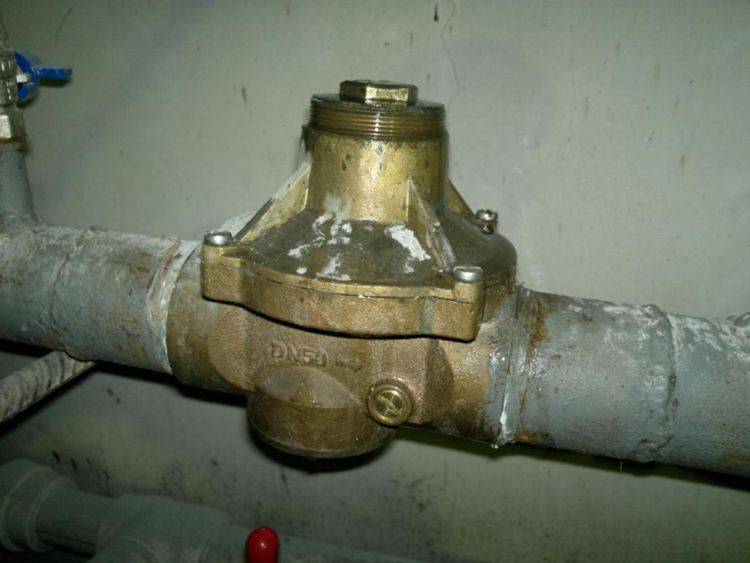
After the water is shut off, the pressure regulator is removed from the pipeline and proceed to its disassembly. Although repairs are allowed without removing the device from the pipe.
Disassembly of the membrane if it drips from the adjustment hole
Step-by-step instruction:
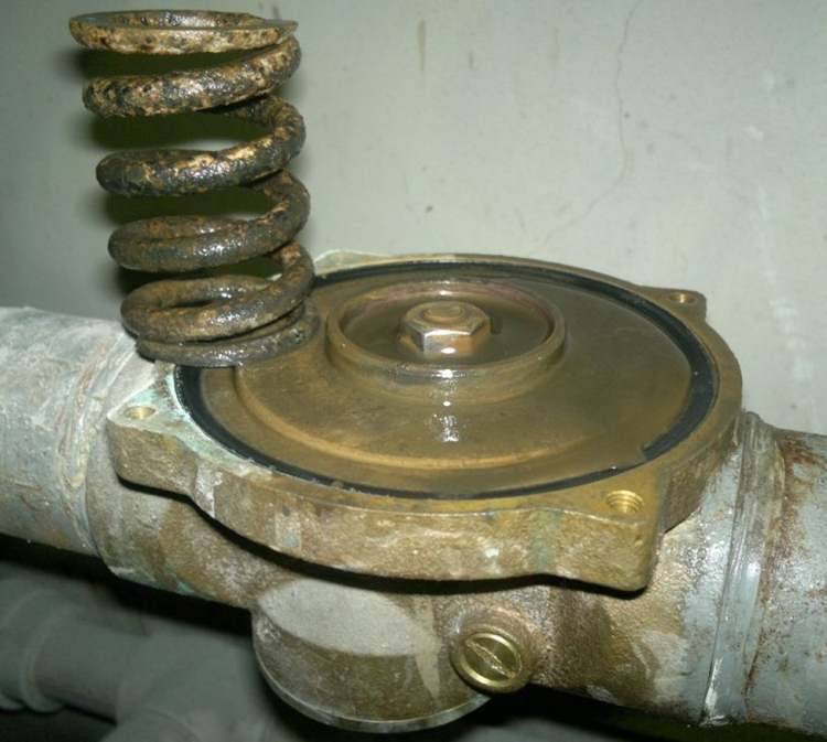
- It is necessary to loosen the fixing nut and loosen the clamping spring. Depending on the design, use a wide slotted screwdriver or a hexagon. In this case, the spring is weakened with an adjustable wrench - it is turned counterclockwise.
- Unscrew 4 bolts and disconnect the housing cover. Under it is a clamping spring and a diaphragm. In the device, the beginning of corrosion of the spring is observed - the membrane passes water. Perhaps the depressurization is caused by the ingress of dirt between the diaphragm and the working compartment.
- They unscrew the lower nut of the gearbox in order to get to the spool and remove the working mechanism - use an adjustable wrench.
- Now the spool is unscrewed - to do this, holding the nut in the body from below (it is more convenient to hold it with a spanner wrench), unscrew the nut from above, the one that is under the clamping spring. You can unscrew and vice versa - as it is more convenient. After that, the spool and diaphragm are taken out of the housing.
- The elements of the clamping mechanism are cleaned of dirt - for this purpose, you can use a soapy water solution. It is strictly forbidden to clean with abrasives - you can violate the integrity of the diaphragm. The body needs to be washed - a rust converter is used for cleaning. The grooves of the body (where the diaphragm is pressed) are recommended to be polished.
- If the elements are not deformed, there are no cracks or other defects, then they are installed in the housing in the reverse order.

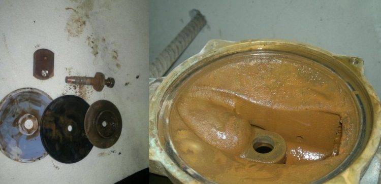
In this case, the leak through the adjusting hole was caused by loose contact between the reducer membrane and the grooves of the working chamber. Removing the dirt made it possible to completely eliminate the leak.
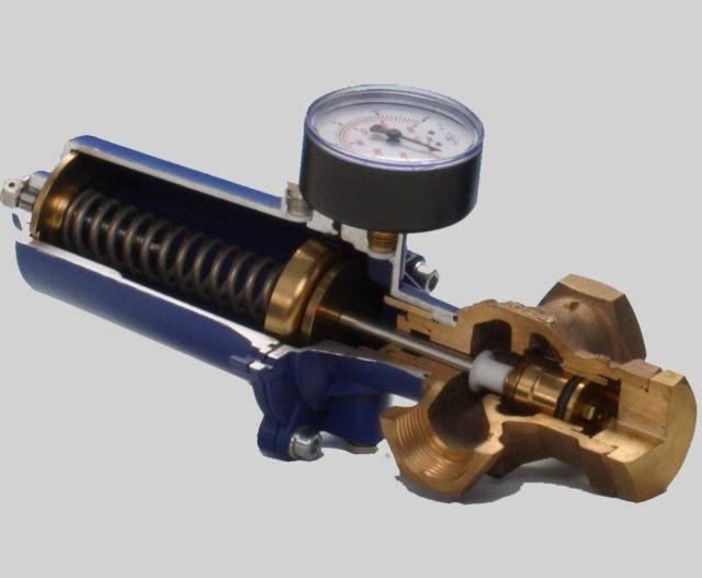
Elimination of leaks in the piston
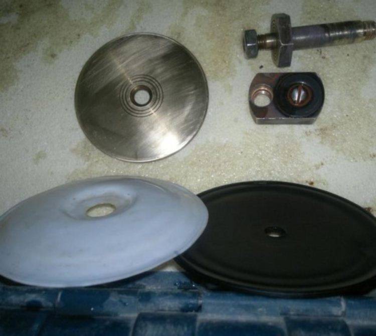
The piston gearbox differs slightly from the membrane one - instead of a diaphragm, it uses a piston with two platforms: small and large. The latter isolates the working chamber from the spring compartment.
If the seal is broken, then water fills the spring compartment and comes out through the thread of the adjusting screw - this is how a leak occurs.To eliminate it, you need to disassemble the gearbox.
Disassembly is allowed without removing the regulator from the pipe:
- As in the case of the diaphragm type, first loosen the clamping spring - usually with a wide slotted screwdriver, turning it counterclockwise.
- Unscrew the top cover of the adjustment compartment from the body - use an adjustable wrench.
- Unscrew the bottom plug or pressure gauge, if provided.
- The piston mechanism is taken out - for this, the spool nut is held (with a socket wrench), and the nut is unscrewed from above.
- Rinse the piston mechanism - use a soft brush. Clean the spring with a rust converter.
- The clamping rings are replaced with new ones, and the pressure regulator is assembled in the reverse order.
These measures should completely prevent leakage through the adjusting screw.
To improve the sealing of the working chamber, it is recommended to polish the inner cylindrical surface of the regulator with a soft nozzle using a drill, and treat the rubber seals with graphite grease.
These measures will help reduce the friction of the piston in the body of the device, which will significantly increase the service life of the seals.
In the event of a leak through a plug in the hole or a pressure gauge, the connection is sealed again - the rubber seal is changed, or the plug is simply insulated with fumlent or plumbing linen with sealant.
If the plug in the hole is defective, then it needs to be replaced - brass, suitable in size, is used as a replacement.
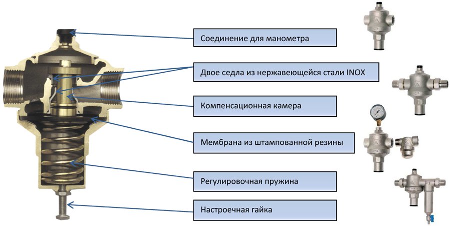
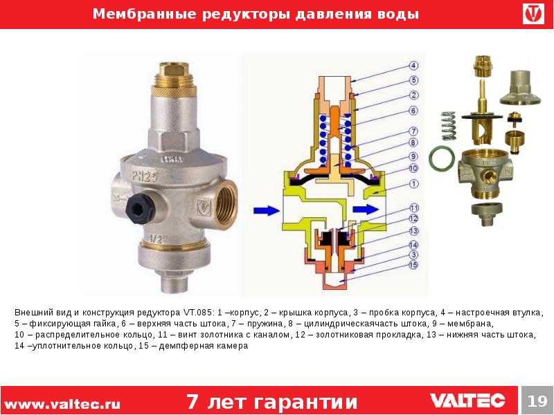
Principle of operation
All 3 types of water pressure reducers (piston, membrane, flow) have a similar principle of operation. At a certain level of pressure in the water supply network, a valve equipped with a spring is activated.The pressure is brought back to normal by adjusting the width to which the valve opens.


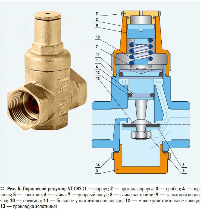
In piston reducers, the water flow is adjusted using a piston with a spring. The required level of output pressure is set by rotating the valve, which weakens or compresses the spring. The latter controls the piston, forcing it to decrease or increase a special hole through which the liquid passes.
In membrane devices, the main control element is a membrane placed in a special chamber that protects it from clogging due to its tightness. The membrane is connected to a spring, which, when compressed, exerts pressure on the water reducer valve, which is responsible for the throughput of the device. The latter decreases or increases in direct proportion to the degree of compression of the spring.
The device of flow reducers resembles a labyrinth with many turns and channels, either dividing the flow of water into several components, or again uniting it. These manipulations achieve a decrease in water pressure at the outlet.
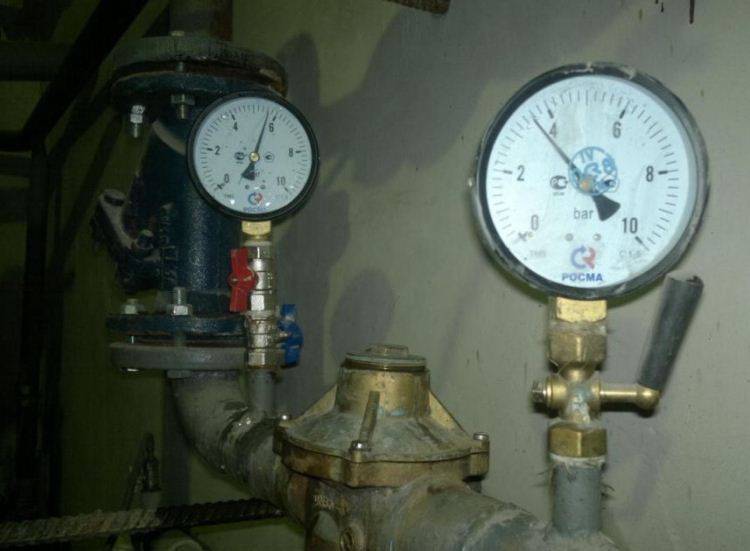
Why you need to monitor the pressure in the boiler
The operation of the boiler is accompanied by changes in the pressure in the circuit, which should be kept within the established limits. This means that when the boiler is turned on, the pressure gauge must show the minimum bar value, and during operation, the pressure cannot exceed the allowable mark. Thus, three types of pressure are determined:
- dynamic pressure is the voltage value of the coolant circulating in the heating circuit;
- static pressure - measured at idle and determines the load exerted by the coolant on the heating circuit;
- maximum pressure - the limit of the permissible load at which normal operation of the system is allowed.
If the pressure in the gas boiler increases, then the result is the cessation of normal operation of the system, water is periodically released through the relief valve or from the expansion tank.
Causes of pressure increase in case of boiler damage
It is difficult for a person who does not have experience in servicing heating systems to independently determine the true reason why the pressure in the heating boiler rises. However, a list of probable causes is provided to provide an idea of possible malfunctions.
- Pressure increase up to 1 atm. may occur as a result of depressurization of the heat exchanger. Such consequences are caused by the formation of cracks in the body during prolonged operation. The appearance of cracks can be the result of manufacturing defects or weak material strength, the consequences of water hammer or equipment wear. In this case, the volume of the coolant systematically begins to replenish. However, it is not possible to visually determine the location of the leak due to the instantaneous evaporation of the liquid when the burner is running. This fault leads to the replacement of the heat exchanger.
- An increase in pressure can occur when the make-up valve is open. The low pressure inside the boiler contrasts with the increased pressure in the piping. This leads to the flow of additional water through the open valve. Thus, the water pressure will gradually increase until the moment of release. If the pressure in the pipeline decreases, then the water supply to the boiler is blocked by the coolant, reducing the pressure in the circuit.The make-up valve must be kept closed, and if it is broken, it must be replaced.
- An increase in pressure may occur due to a malfunction of the three-way valve. Such a breakdown leads to water entering the circuit from the expansion tank. Rubbish periodically collects on the valve, which can cause it to break. This element must be periodically cleaned, and in the event of a malfunction, replaced. To prevent the ingress of contaminants from the water supply, you can install a simple corner filter.
- If all signs indicate that the pressure in the circuit is increasing, and the pressure gauge needle does not respond, this means that it is out of order. A broken device deprives the way of exercising control over the operation of the system and needs to be replaced.
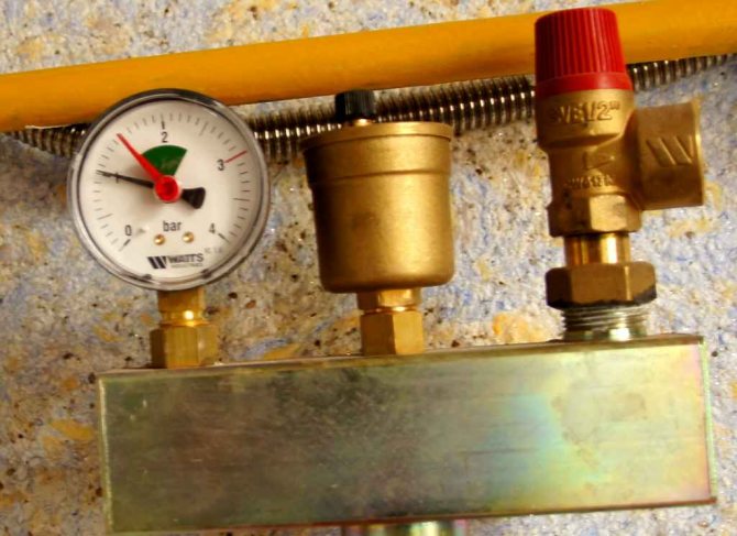
Excessive pressure in the heating circuit is determined by the readings of the pressure gauge, if the indicator exceeds the permissible mark, measures must be taken immediately. In addition to the pressure gauge, a safety valve can indicate that the permissible norm is exceeded, from which water will begin to flow if the pressure has risen.
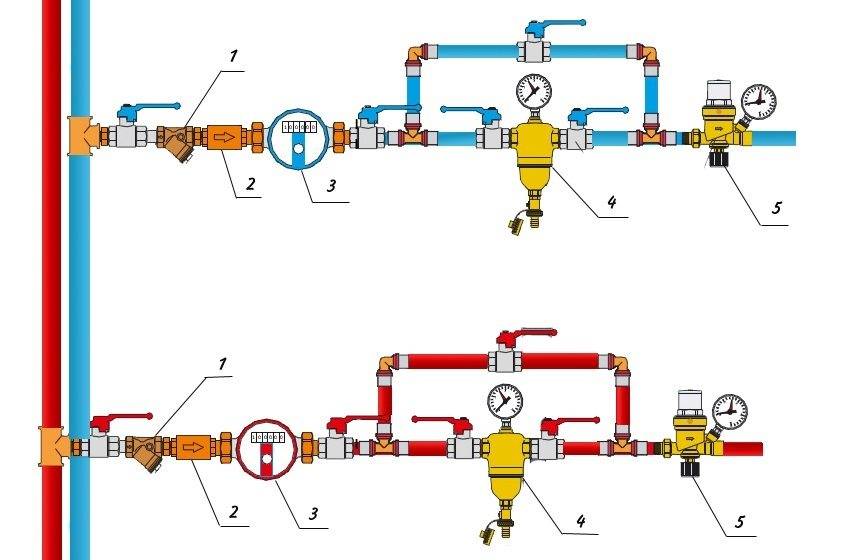
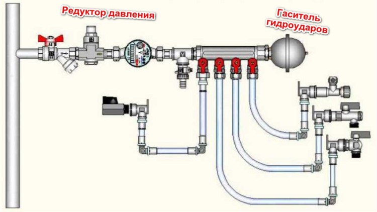
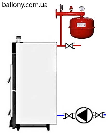
Automatic make-up unit
If you are firmly confident in the reliability and build quality of the system, you can mount an automated circuit that adds water from the cold water pipe. What to buy:
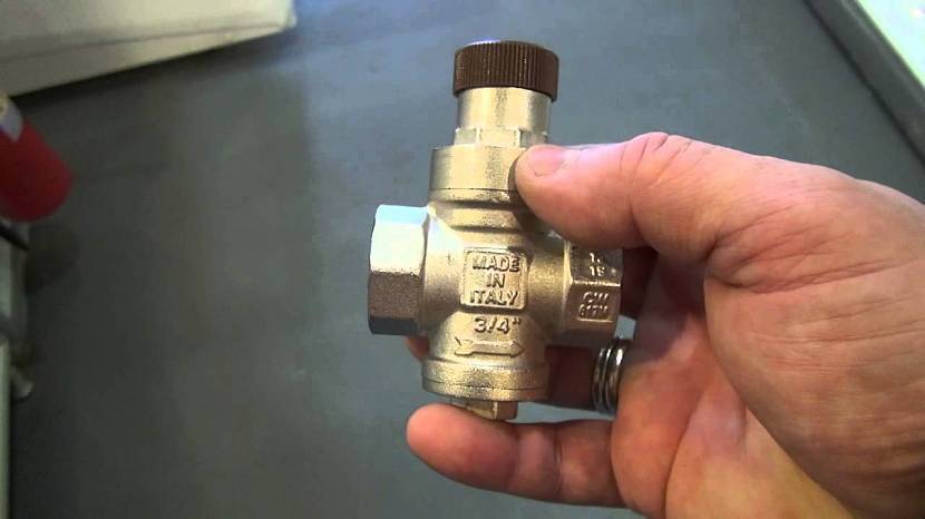
pressure reducing valve (easier - reducer);
3 ball valves;
2 tees;
pipe for the bypass device.
An important point. The water entering the reducer must be pre-cleaned with a coarse mesh filter, otherwise the valve will quickly become clogged. If such a filter is not provided at the entrance to the building, install it in front of the make-up unit.
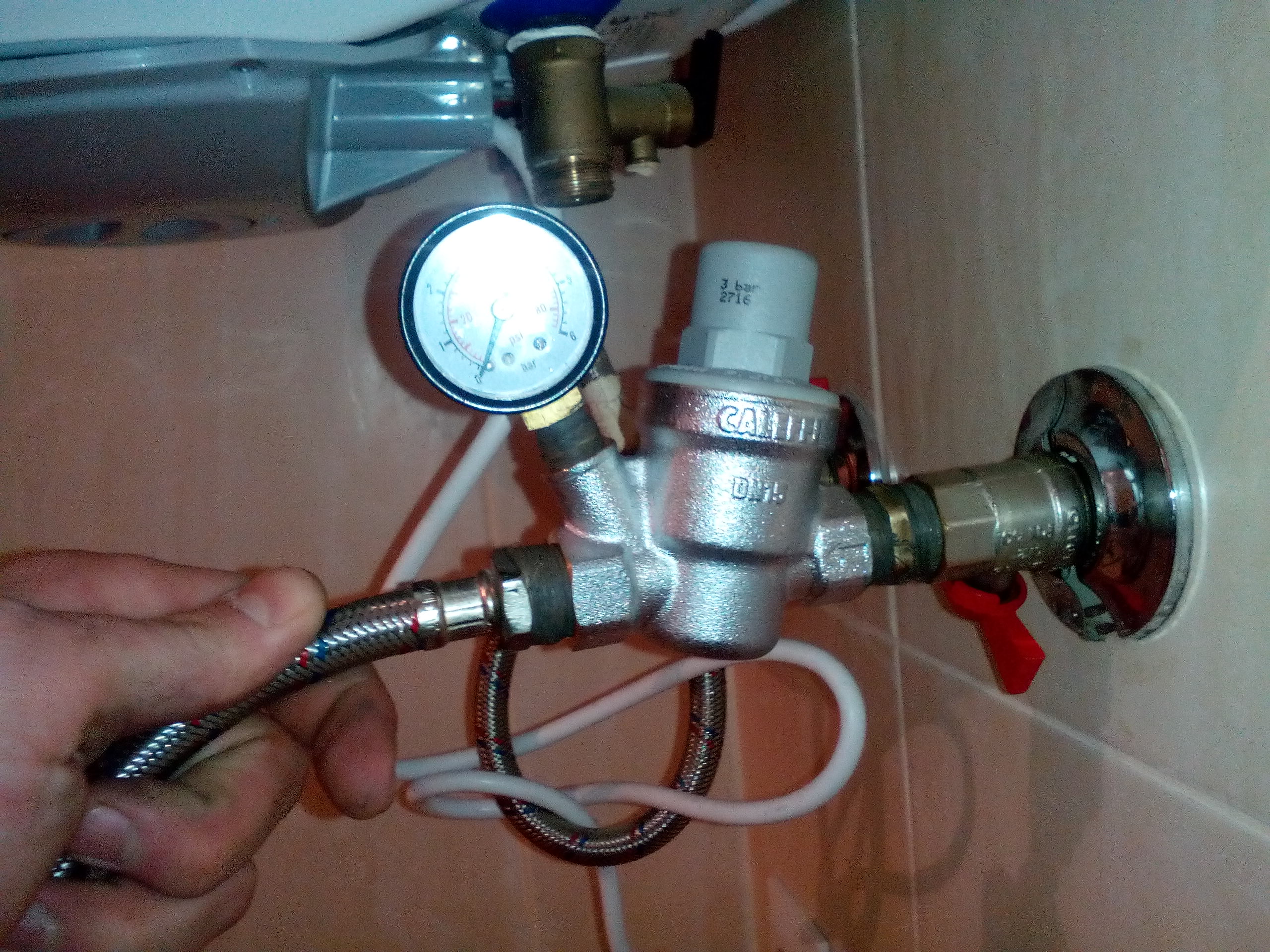
In this scheme, the pressure gauge shows the pressure on the side of the heating network, the bypass and taps are needed to service the make-up module
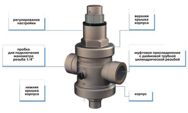
The main actuating element of the circuit - the gearbox - consists of the following parts:
- fine filter at the inlet pipe;
- spring seated valve with rubber seals;
- pressure regulator handle with printed scale, range - 0.5 ... 4 bar (or higher);
- manual shut-off valve;
- outlet check valve.
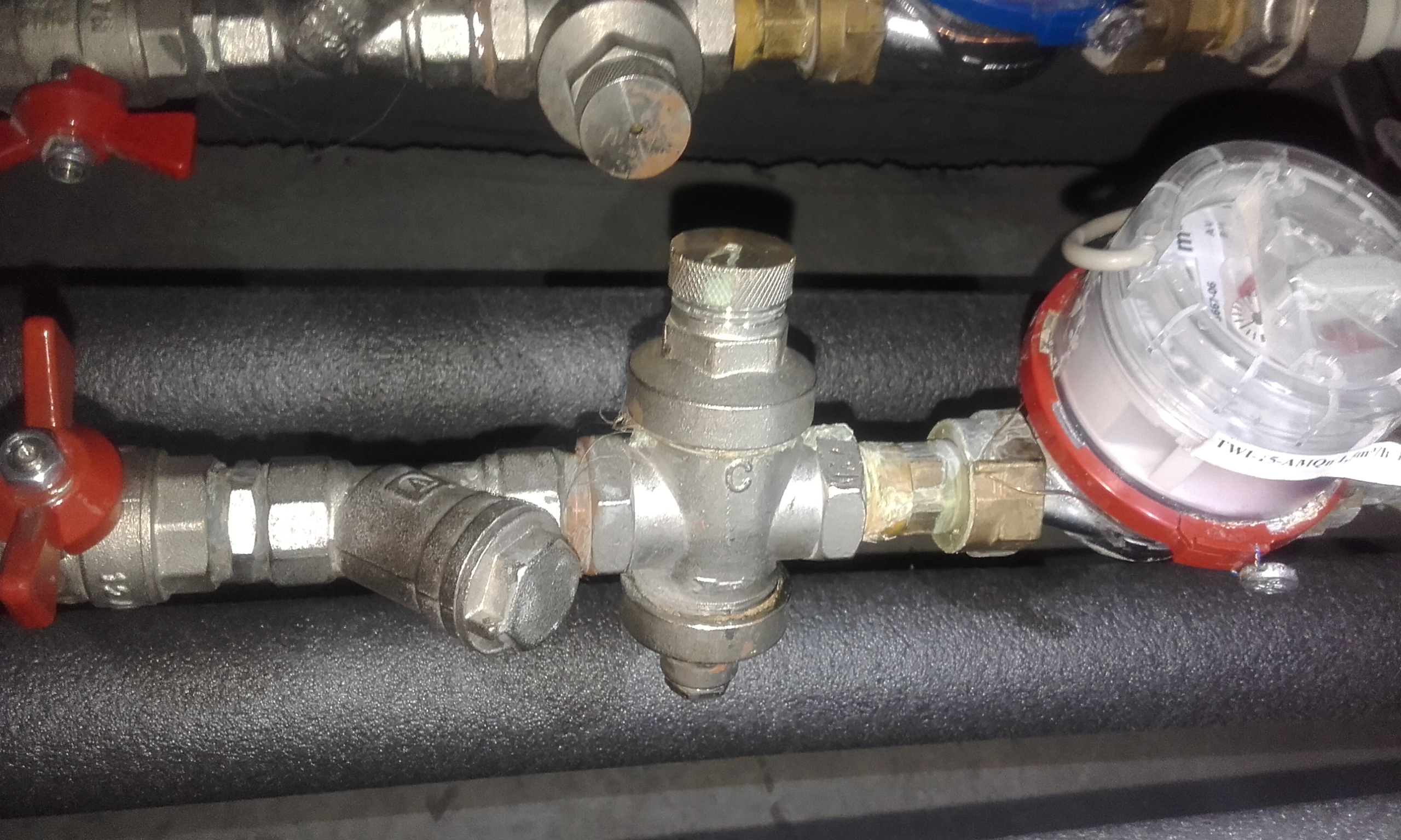
As you can see, the reduction machine already contains all the necessary elements - a filter, a check valve and a regulator. It remains to assemble a simple circuit with a bypass and service valves designed to remove and service the gearbox.
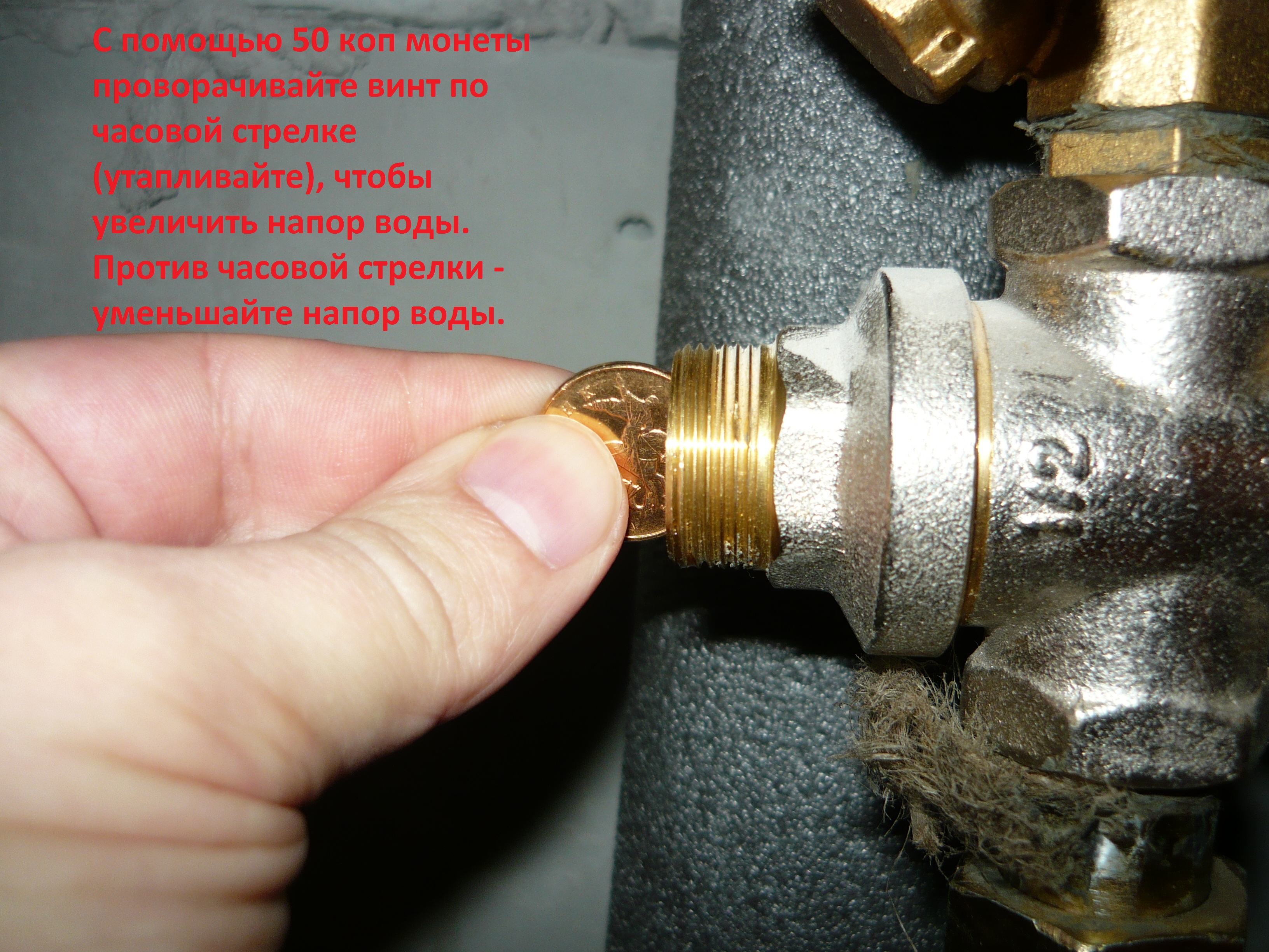
It is easy to control the valve - use the regulator to set the minimum pressure threshold in the heating system, open the valves of the direct line, and close the bypass. How to properly adjust the automatic valve is shown in a short video:
To organize the automatic addition of antifreeze to the system, you can adapt a "hydrofor" - a water station with an electric pump designed for water supply from a well. The pressure switch of the unit must be reconfigured for a minimum pressure of 0.8 bar, a maximum pressure of 1.2 ... 1.5 bar, and direct the suction pipe to a barrel with non-freezing coolant.
The feasibility of this approach is highly questionable.
- If the "hydrofor" works and begins to pump up antifreeze, you still have to look for and fix the cause of the problem.
- With a long absence of the owners, make-up will also not save the situation in the event of an accident, since the size of the tank is limited. The pumping station will extend the heating operation for some time, but then the boiler will turn off.
- Putting a large barrel is dangerous - you can flood half the house with toxic ethylene glycol. Non-toxic propylene glycol is too expensive, as is spill cleanup.
Examples of organizing automatic refueling from containers of different capacities
Conclusion. Instead of additional pumps and automatic gearboxes, it is better to purchase an electronic unit of the Ksital type. After a relatively inexpensive installation, you will be able to control the operation of the heating through a cell phone or computer and quickly respond to emergencies.


When do you need to adjust and remove the default settings?
The input power does not always correspond to the standard 5.0 - 6.0 bar. If the pressure in the supply network differs significantly from the standard, then the pressure of the water after the reducer will be different from the factory settings.
For example, consider a regulator set to 3.0 bar with an inlet pressure of 5.0 bar. That is, a difference of 2.0 bar.
If the inlet pressure is 2.5 bar, then the output value will be only 0.5 bar, which is very low for normal use. Setup required.
If the inlet head is 7.0 bar, then the output value will be 5.0 bar, which is a lot. Setup required.
Deviation from the standards can be under the following conditions:
- water consumption significantly exceeds the capacity of central networks and pumping stations, the pressure will be low;
- upper floors of tall buildings, low pressure;
- the lower floors of tall buildings, the pressure will be high;
- incorrect operation of booster pumps in the building, the pressure may be low or high.
In such situations, it is necessary to reconfigure the gearbox.A change in the inlet water pressure can also occur during the long-term operation of water supply networks. Including due to a decrease in the flow area of pipes in the building due to the formation of deposits and corrosion.
Adjustment may be required more than once, during long-term use of water.
Gearboxes are subject to wear resulting in water leakage. They can be repaired, which requires disassembly. After assembling the device, it will need to be adjusted.
System Diagnostics
A pump failure is not a reason to jump to the conclusion about a faulty pressure switch, and there is no need to rush to try to repair or adjust it right away.
You need to take some simple steps first:
Carefully inspect the water supply system for leaks.
Check and, if necessary, clean the filters.
Pay attention to the pressure in the hydraulic accumulator of the station.
The reasons for periodic shutdowns, and subsequently its complete stop, may be:
- Air lock in the intake line and the discharge section of the pump.
- Shredding of the source.
- Damaged or clogged pump check valve.
- Faulty accumulator membrane.
- Reducing the pressure in the accumulator.
The airing of the water supply system can be understood by the bubbles and the interruption of the water flow. To solve the problem, it is often enough to check the tightness of the connections and replace the worn stuffing box.
In other cases, cleaning of filters, maintenance or replacement of failed equipment is required.
Prevention of the problem
Due to their simplicity and trouble-free operation, piston devices are widely used.However, their durability directly depends on their ongoing maintenance, which is recommended to be done at least once a year.
It consists in replacing all sealing rings, treating them with graphite grease, and also lubricating the pressure spring with an anti-corrosion compound.
It is recommended not to allow the device to freeze - this deforms its parts and inevitably leads to a leak. Therefore, control valves should only be located in a heated room.


The main reason for premature failure of regulators is rust, scale and other dirt. To increase the service life, it is recommended to carefully monitor the cleanliness of the filters at the inlet - it is necessary to clean the coarse filter mesh at least 2 times a year.
If possible, install the mechanisms in a horizontal position - this helps to avoid uneven wear of the sealing elements on the moving parts.
Regulators are mistakenly referred to as devices that reduce water hammer - they do not extinguish them, but only slightly reduce them, which does the rest of the plumbing fittings:
- filters,
- cranes,
- flexible hoses, etc.
Like other devices against water hammer, pressure regulators have a reduced service life. Therefore, in order to extend their service life, it is recommended to equip the water supply system with special water hammer dampers.
Kinds
Piston
The simplest in design and the cheapest, and, consequently, the most common. They contain a spring-loaded piston that covers the cross section of the pipeline, thereby regulating the outlet pressure. Ordinary adjustment range - from 1 to 5 atm.
The disadvantage of such regulators is the presence of a moving piston, which imposes requirements for pre-filtering the water at the inlet of the gearbox, as well as limiting the maximum flow rate, leading to increased wear of moving parts.
Membrane
Adjustment is provided by a spring-loaded diaphragm installed in a separate sealed chamber and providing opening and closing of the control valve.
Such gearboxes are distinguished by high reliability and unpretentiousness, a large range and proportionality of pressure adjustment, as well as a large spread in the operating flow rate, ranging from 0.5 to 3 cubic meters. m/h They also differ in higher cost.
Flowing
They provide dynamic pressure regulation due to the internal labyrinth located in the body and reducing the flow rate by its division and numerous turns. They are mainly used for watering and irrigation systems.
Due to the absence of moving parts and the use of plastic materials for their manufacture, they are distinguished by a low price, however, they require the installation of an additional regulator or valve at the inlet. The operating range is from 0.5 to 3 atm.
Wiring diagram
Pressure switches for compressors can be for different load connection schemes. For a single-phase engine, a 220 volt relay is used, with two groups of connections. If we have three phases, then install a device for 380 volts, which has three electronic contacts for all three phases. For a motor with three phases, you should not use a relay to the 220 volt compressor, because one phase will not be able to turn off the load.
flanges
Additional connection flanges may be included with the device.Usually equipped with no more than three flanges, with a hole size of 1/4 inch. Thanks to this, additional parts can be connected to the compressor, for example, a pressure gauge or a safety valve.
Pressure switch connection
Relay installation
Let us turn to such a question as connecting and adjusting the relay. How to connect the relay:
- We connect the device to the receiver through the main output.
- If necessary, connect a pressure gauge if flanges are present.
- If necessary, we also connect an unloading and safety valve to the flanges.
- Channels that are not used must be closed with plugs.
- Connect the electric motor control circuit to the contacts of the pressure switch.
- The current consumed by the motor must not exceed the voltage of the pressure switch contacts. Motors with low power can be installed directly, and with high power they put the necessary magnetic starter.
- Adjust the parameters of the highest and lowest pressure in the system using the adjusting screws.
The compressor relay should be adjusted under pressure, but with the engine power off.
When replacing or connecting a relay, you should know the exact voltage in the network: 220 or 380 volts
Relay adjustment
The pressure switch is usually sold already configured and adjusted by the manufacturer, and does not need additional adjustments. But sometimes it becomes necessary to change the factory settings. First you need to know the range of parameters of the compressor. Using a pressure gauge, determine the pressure at which the relay turns on or off the motor.


After determining the desired values, the compressor is disconnected from the network. Then remove the relay cover. Under it there are two bolts of slightly different sizes.The larger bolt adjusts the maximum pressure when the engine should be turned off. Usually it is denoted by the letter P and an arrow with a plus or minus. To increase the value of this parameter, the screw is turned towards the "plus", and to decrease - towards the "minus".

The smaller screw sets the pressure difference between on and off. It is indicated by the symbol "ΔΡ" and an arrow. Usually the difference is set at 1.5-2 bar. The higher this indicator, the less often the relay turns on the engine, but at the same time the pressure drop in the system will increase.
Causes of pressure drop
The reasons for the pressure drop in the gas boiler are as follows:
- Water is leaking from the heating system.
- The electricity was out for a long time.
- Malfunctions of the expansion tank GK.
- Incorrect selection of the boiler.
Due to low pressure, the boiler stops working. When the water pressure in the heating network reaches the minimum mark, the water does not go to the HC. When the gas pressure drops in the boiler, it immediately turns off automatically. To avoid such difficulties, it is necessary to carry out regular maintenance of such devices. To do this, you need to invite specialists from the service department.
Why does pressure drop occur in the accumulator
Most likely, the pressure drops due to air leakage. The reason is in the pressure line itself. Repair of an electric compressor consists of a thorough inspection of the pipeline. To do this, prepare a soap emulsion and coat the joints in the pipeline. If a leak is found, it is treated with sealing tape.
The air outlet cock of the receiver is capable of passing air when it is loose or has become unusable.
The piston head of the compressor is equipped with a control valve, which can also cause the device to malfunction. The cylinder head is disassembled, but air is first released from the accumulator. If this operation does not help, then the valve must be replaced.