- An example of calculating the dimensions of the furnace
- How to make a waste oil boiler with your own hands
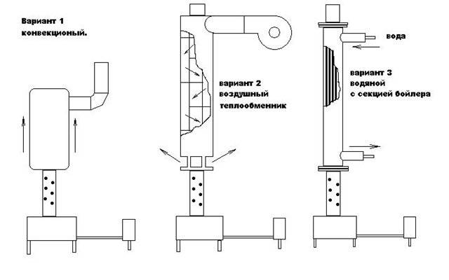
- Option number 1
- Option number 2: a boiler based on a potbelly stove
- Self-production
- Drawings and assembly diagram
- Pressurized drip ovens
- Do-it-yourself step-by-step instructions for making a waste oil furnace from a cylinder
- Making a pallet for working out and installing a chimney of an oil stove with your own hands
- Connecting the structure in the bath
- Safety regulations
- Instructions for using the oven
- The design and principle of operation of the heating device
An example of calculating the dimensions of the furnace
As mentioned above, fuel consumption is about 1 ... 2 liters per hour. At the same time, the radiated heat is about 11 kWh per liter. Thus, the furnace can produce 11 ... 22 kW per hour. To calculate the required volume of the furnace, taking into account the burning time, we accept:
- the volume of the room (garage) - 7x4x2.5 \u003d 70 cubic meters, area 28 sq.m.;
- we believe that at least 500 W are required for each square meter of a garage-type room (basic 100 W, we enter coefficients for all external walls, an uninsulated roof and foundation, a large entrance opening, a metal structure);
- accordingly, an area of 28 squares requires 14 kW of energy per hour.
Slightly forcing the stove to the minimum power (increasing the draft), we will get the required temperature in the room. But fuel consumption will increase to about 1.5 ... 1.6 liters per hour.Therefore, for a burning time of at least 6 hours, the volume of the furnace must be 10 liters. This corresponds to 0.001 cubic meters, that is, the container should have a size, for example, 10x10x10 cm. In reality, the volume of the furnace exceeds the required volume of fuel by 1.5 ... 2 times, that is, the dimensions should be 20x10x10 cm or more, for a mini stove it is suitable. Usually taken with a solid margin, that is, 50x30x15 cm. This allows you not to add fuel every time you ignite.
Important: with large sizes of the furnace, it becomes necessary to extinguish the fire in the furnace during mining before the fuel burns out completely. The quenching process is shown in the video ..
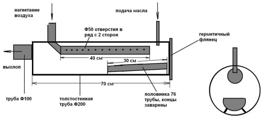
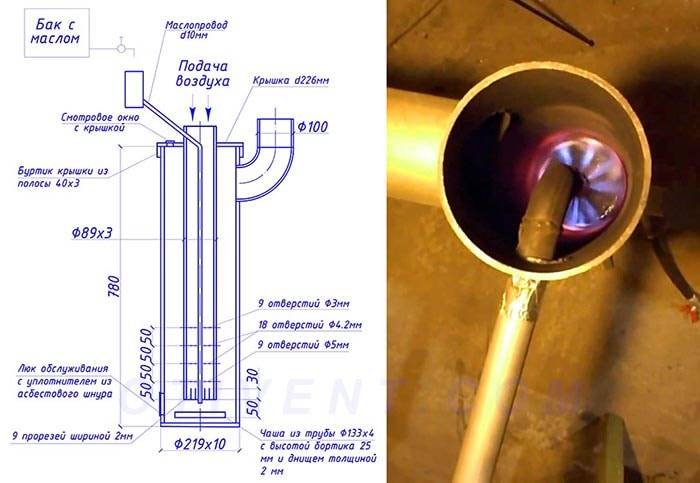
The length of the pipe is 40 cm, respectively, its diameter is 10 cm. The area of \u200b\u200bthe lateral surface of the cylinder is equal to its height multiplied by the circumference of the base (diameter multiplied by the number π), in our case 40x3.14x10 \u003d 1256 cm2. Accordingly, the area of all holes is one tenth of the total - 125.6 cm2. Considering that the area of one hole with a diameter of 10 mm is πx0.52=3.14x0.25=0.78 sq.cm, such a pipe will require 125.6/0.78=160 holes.
Note! The accepted value - the area of the holes is 10% of the total area of the side surface of the pipe - conditionally! The number of holes in the manufacture is taken, among other things, from the strength of the product and is usually noticeably less!
Considering that the expanded cylinder is a 31x40 cm rectangle, and the holes should be placed in a checkerboard pattern, we will have to make 12 vertical rows of 13 or 14 holes each. Marking the vertical rows is simple - divide the upper or lower circumference of the pipe base into 12 parts in any geometric way and draw vertical drilling lines.
The distance between the rows will be 3.3 cm. Marking the vertical rows is a little more difficult, since it is necessary in every second row to shift the upper (or lower) marking point by half the distance between the holes. Considering that we need to make holes not on the edge of the pipe, we add 1 to the planned number of holes and calculate the step: for 13 holes it will be 40 / (13 + 1) \u003d 2.85 cm, for 14 - 40 / (14 + 1) \u003d 2.6 cm.
Important: when drilling, the axis of the drill must be directed towards the axis of the pipe!
How to make a waste oil boiler with your own hands
There are various design options for waste oil boilers. They are even sold in the store.
Option number 1
To make a simple waste oil boiler with your own hands, you will need the following parts and equipment:
- oil pump and circulation pump;
- special burner and air compressor;
- ready-made boiler, which has a built-in expansion tank;
- pipe sections to equip the highways.
Manufacturing steps:
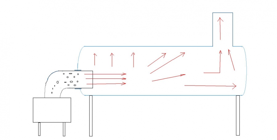
- Exhaust is fed into the forced evaporation chamber through an oil-resistant hose using an oil pump directly from the fuel tank. To make such an evaporation chamber, you should take a piece of strong and thick pipe that will be able to withstand temperatures reaching 400 degrees.
- A small tube should be placed in the center of this chamber; it is used to supply air blown by a fan into it.
- Vapors, enriched by the influx of air masses, burn out in the working chamber, thus heating the coolant that circulates through the pipe lines.
Components of the boiler (all dimensions are in centimeters)
To make a high-quality installation of all elements of the system, you will need a welding machine, as well as skills in handling it.
Such a boiler will provide a power of 5-10 kilowatts. This is enough to thoroughly warm up a room up to 40 square meters. m.


Option number 2: a boiler based on a potbelly stove
The easiest way to heat a boiler is to make a potbelly stove boiler. It will consist of two compartments, the first will contain the filled used oil.
Combustion of fuel will be carried out in stages. First, the fuel burns in the first compartment at a moderate temperature. In the second, there will be combustion of products mixed with air, which are obtained due to the combustion of used oil. The temperature in the second compartment will be about 800 degrees.
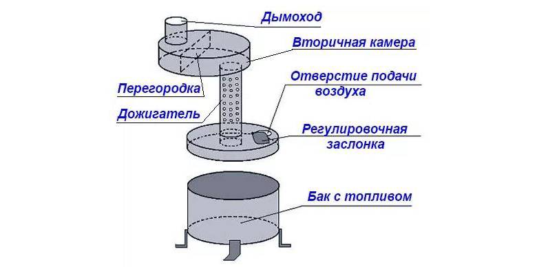
The general scheme of the device of a potbelly stove for working out
In the manufacture of such a boiler, it is necessary to provide additional air supply to both combustion chambers. A hole is made in the lower tank for this - it will serve for pouring fuel, as well as for air access. To control the air supply, the hole is equipped with a damper. Air will enter the upper chamber through small holes with a diameter of about 10 mm. They should be drilled in the pipe, from where combustion products will be supplied from the first chamber, it will connect both compartments.
To make a boiler you will need:
- Welding machine (minimum 200 amps).
- Perforator and grinder. The grinder should be taken with cleaning and cutting wheels, as well as a circle diameter of at least 125 mm. For a perforator, the diameter of the drill should be taken at least 13 mm.
- Sledgehammer.
- Carrying.
- A hammer.
- Rivets.
- Chisel.
- Leg corner.
- Pliers.
- Safety goggles for welding.
Boiler manufacturing process
- First of all, you should weld the tank, which will serve as the lower container, where the used oil will be located. It should be made from sheet metal.
- Then, in the boiler, you need to cut a hole necessary for air to be supplied.
- Then you need to install a valve, it will regulate the air supply. You can fix it with rivets.
- Instead of a chimney pipe, you can put a pipe with holes designed for air flow.
- Make a chamber with a removable cover designed for the second compartment.
- Connect the prepared chamber to the pipe with holes, where secondary combustion will take place.
- Connect the upper chamber to the lower one, there should be no gaps.
- The design for stability should be fastened with a corner.
- Connect the chimney pipe in a vertical position.
- To ignite the boiler, fill in the used oil, then set it on fire with plain paper.
These are good options for a do-it-yourself heating device for a private house, which are available to many for sale.
Self-production
Anyone can make the simplest design. There are quite a few schemes on how to do this, they can be used to understand the entire production process.
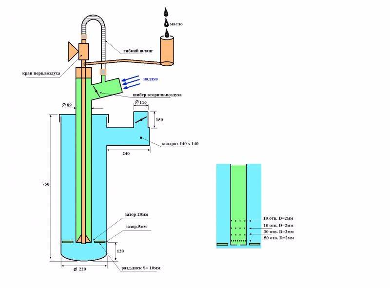
It will be more interesting to consider a supercharged waste oil furnace. There are also enough drawings, but the design is more complex, and therefore requires additional knowledge in this area.
Its main advantage is that it will not throw energy into the street in large quantities, but a slow heat extraction will be organized.The second significant difference is the presence of a drawer for oil, which makes it easy to clean. In simpler (completely closed) containers, this is extremely difficult to do.
The diameter of the pipes and the volume of the oil tank must be selected based on the quadrature of the heated room.
For an average garage with dimensions of 3x6 m, you will need parts of the following sizes:
- profile pipe 75 × 75 × 4 cm;
- fuel box 55×55×4 cm.
For self-production, you must perform the following step-by-step actions:
- Cut the elements of the drawer. Afterburner pipes need to be cut at a 45° angle.
- In a smaller profile, a hole for the box is cut out with a grinder, and the sides are welded on the sides. A handle is attached to the box.
- The structure is welded together, and a hole for the chimney is drilled from above.
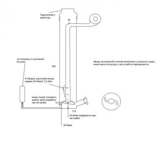
For more efficient operation and maximum heat extraction, it is recommended to attach an extension in the form of a 3-meter pipe to the stove. It will burn the fuel. But for a higher degree of security, it is recommended to sheathe the walls of the garage near the stove with metal sheets, pick up all the wooden shelves and combustible substances.
In this video you will learn about the construction of a waste oil furnace:


At the last stage, it is only necessary to ignite the fuel and adjust the operation of the stove. At the same time, the main task is to minimize the emission of black smoke, as this indicates that there is not enough air in the system. To set this parameter, you need to drill several holes and check the number of emissions. But a large number of holes can do harm. Smoke may escape into the room. Therefore, the number of holes must be adjusted correctly.
Making a dropper is also quite difficult, but such a task is quite feasible. Often, a cylinder with a diameter of 220 to 300 mm is used for the production of a drip furnace in mining. It has fairly thick walls so as not to burn for a long time. A steel pipe with a diameter of 5 mm or more may also be suitable.
An ideal option for these purposes is to use a heat-resistant chrome pipe with a diameter of 3 mm or more. But production will be cheap only if the pipe is already available. It is not worth buying this specifically, as manufacturing will be expensive.
All other details can also be found in the household or the radio market. For example, a Zhiguli fan is well suited for supercharging. Metal pipes and other elements are available at scrap metal collection points.
The production technology of the drip oven is as follows:
- The bowl for the flame is made from a pipe or a finished steel container is taken. The pallet should not be too large, as the pipe must be removed through the hatch.
- In the case, with the help of a grinder, openings for the chimney and the cleaning hatch are cut out.
- An afterburner is being made. You do not need to make all the holes at once. It is better to make a third of the maximum amount set in the drawing, and complete all the rest during the setup process.
- A cover and an air duct are welded to the afterburner. In the latter, a fan is mounted.
- The device is assembled, adjusted and its operation is checked.
In order for the device to come out really reliable, it is better to place it in a steel case. It must be welded from profiled pipes. To adjust the temperature, it is necessary to provide for the possibility of changing the amount of fuel supplied, as well as blowing the fan.
Experienced users have learned to adjust the amount of fuel burned by eye. If the oil is supplied in drops, then less than 1 liter per hour burns out, and if a small stream is observed, then more than 1 liter. To install an easy adjustment of the air supply, you can purchase a cheap PWM on the Chinese market.
After assembling the entire structure, it is necessary to check its operation. The procedure does not differ from the previous recommendations. It is required to achieve the cleanest smoke possible and at the same time not to overdo it with the holes in the igniter.
If a person has a certain experience, then it is not difficult to make even a complex potbelly stove using spent fuel. If a novice master has never been interested in this area, then the simplest design from improvised materials will do.
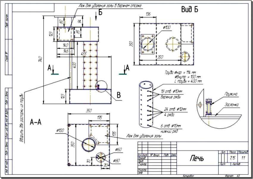
Drawings and assembly diagram
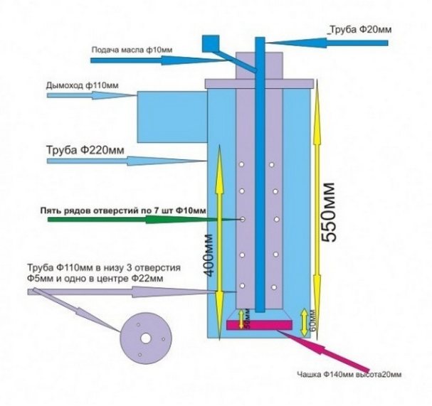
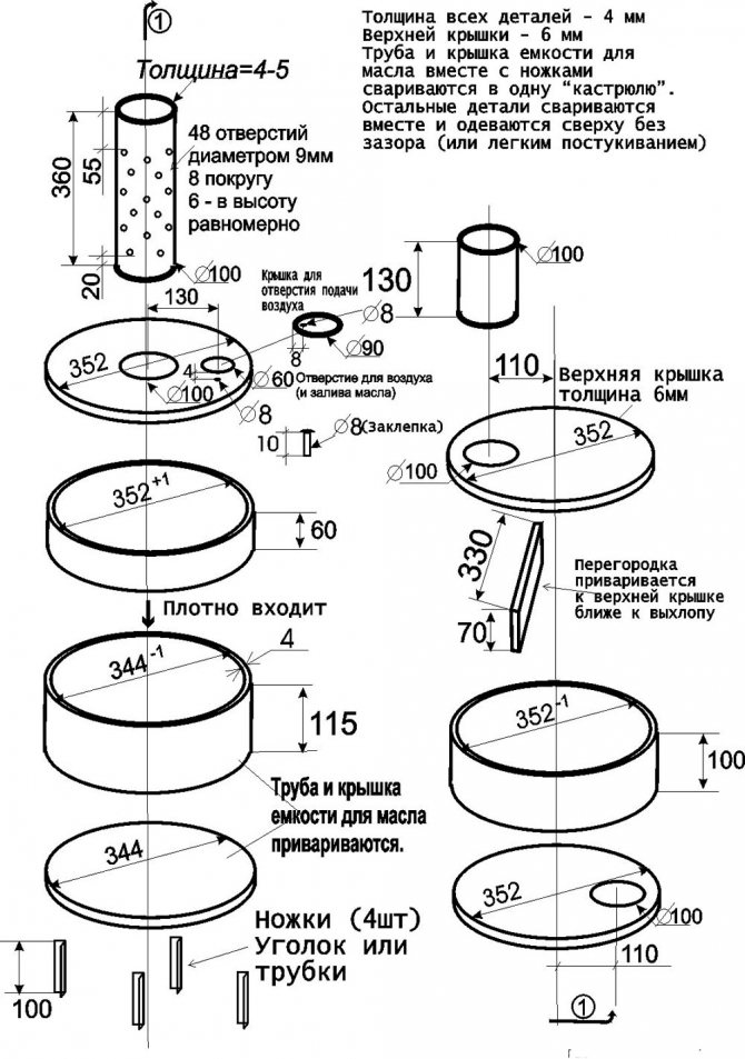
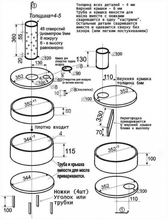
The manufacture of the furnace begins with the lower chamber. It is combined in the stove with a fuel tank, on the lid of which special holes are made for the mining bay and for the pipe connecting the first chamber to the second.
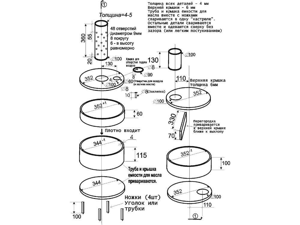
According to the dimensions shown in the figure, parts of the primary combustion chamber are cut out, the edges are ground and welded. The walls are made from a pipe blank.
Corners are welded to them, which will become legs, a sheet of metal is welded to the bottom. A 10 cm hole is cut in the center, and another 6 cm on the side, closer to the edge. If desired, make a removable cover - it is easier to clean the tank.
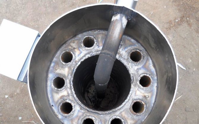
In a pipe 36 cm long and 10 cm in diameter, up to 50 holes with a diameter of 9 mm are drilled evenly over the entire area of \u200b\u200bthe pipe so that the air flow is the same on each side.
A pipe with holes made is welded perpendicular to the tank lid.An air damper is made on the lower tank. Secure it with bolts or rivets. Through this hole, the furnace will be ignited and mining will be filled.
The top tank is done in the same way as the bottom one. In the plate, which is attached at the bottom of the tank, a hole with a diameter of 10 cm is made, shifted to one of the edges. A piece of pipe with a large diameter from the hole is welded to the hole below, just enough so that it can be put on the perforated upper combustion chamber.


Since the cover of the upper tank is exposed to the highest temperatures, it is recommended to make it from metal with a minimum thickness of 6mm. At the top of the tank, a hole is made for the chimney, which is opposite to the hole in the bottom. A thick metal plate is placed between them - a cutter. It is inserted closer to the chimney hole.
A pipe is welded to the top cover, which is then connected to the chimney. To improve the stability of the structure, a spacer is welded from a pipe or corner. You can paint the oven with paint for metal that can withstand high temperature conditions.
Pressurized drip ovens
A pressurized stove is the same heating device, only equipped with a fan. It is located closer to the second combustion chamber. The blower provides uniform heating of the room.
Assembling a drip oven is difficult. Industrial heating devices are equipped with the same mechanism. Models of this kind reduce the amount of fuel used.
Modern craftsmen have learned to combine the drip mechanism with supercharging. However, it is strongly not recommended to assemble such a unit without the appropriate skills.
Do-it-yourself step-by-step instructions for making a waste oil furnace from a cylinder
The device can be made from old items using the provided drawings of the waste oil furnace. For this process, you will need a gas cylinder with a capacity of 50 liters. You should also prepare:
- a pipe with a diameter of 80-100 mm and a length of 4 m;
- steel corner for the manufacture of the stand and internal elements of the heat exchanger;
- sheet steel for making the bottom of the upper chamber and the plug;
For the process of manufacturing a waste oil furnace, you will need a gas cylinder with a capacity of 50 liters
- brake disk;
- fuel hose;
- clamps;
- half-inch valve;
- loops;
- half inch oil supply pipe.
An empty gas cylinder is used to make the case. It is necessary to unscrew the valve on it, after which it should be left overnight on the street to ventilate the remaining gas. A hole is drilled in the bottom of the product. To prevent the formation of a spark, the drill must be moistened with oil. Through the hole, the balloon is filled with water, which then drains, washing off the remaining gas.
Two openings are cut in the balloon. The top one will be used for the combustion chamber, where the heat exchanger will be installed. The lower one acts as a burner with a tray. The upper part of the chamber is specially made large. If necessary, it can be filled with other fuel options in the form of firewood or pressed briquettes.
A gas cylinder stove will be more economical and efficient than other materials
Further, the bottom for the upper compartment of the apparatus is made from sheet metal with a thickness of 4 mm. A burner is made from a piece of pipe 200 mm long, as shown in the drawing of a waste oil stove. A lot of holes are made around the circumference of the product, which are necessary for air to enter the fuel.Next, grind the inside of the burner. This will eliminate the possibility of soot accumulation on the ends and uneven surfaces.
The furnace burner for mining from a gas cylinder is welded to the bottom of the upper chamber. In the absence of mining reserves, wood can be laid on the formed shelf.
Making a pallet for working out and installing a chimney of an oil stove with your own hands
According to the stove drawing, the waste oil pan is made of cast iron automobile brake disc, which has good heat-resistant performance. In its lower part, a steel circle is welded, which forms the bottom. A cover is made in the upper part, through the opening of which air enters the furnace.
For the manufacture of the pallet, a cast-iron automobile brake disc is used.
The next step in the manufacture of a waste oil stove from a gas cylinder is to make a coupling from a 10 cm long pipe that connects the burner and the pan. Thanks to this element, it will be much easier to maintain the stove. You can remove the pan and clean the bottom of the burner. To ensure the supply of oil, a metal tube is inserted into the hole in the housing, which is seized by welding. An emergency valve is installed on the pipe.
The chimney structure is made of a pipe with a diameter of 100 mm. One of its ends is welded to the hole in the central upper part of the body, and the other is brought out into the street.
After watching the video "Furnace for working out from a gas cylinder", you can familiarize yourself with the sequence of actions in the manufacture of the apparatus.


Connecting the structure in the bath
The design of the stove includes a part of the chimney with many holes (usually up to 50). This part of the unit is called the burner.In such a burner, oil vapors are mixed with oxygen entering the chimney under the influence of draft. As a result of their mixing, the combustion process begins to be much cleaner and more intense with the release of a huge amount of heat.
The pallet was made from a cast-iron automobile brake disc. Cast iron has good heat resistance, so I decided to take it.
It is from this disk that I will make a pallet
Bottom welded the bottom.
The steel circle is the bottom
I welded a lid on top. In it you can see the counterpart of the burner and the opening. Air enters the stove through the opening. I made it wide - it's better that way. With a narrow opening, the air draft may not be strong enough to prevent oil from entering the sump.
Next I made a clutch. She connects the pan and the burner in my stove. With a clutch, servicing the stove will be much easier. If necessary, I can take out the pan and clean the burner from below.
Next I made a clutch
The coupling was made from a 10-centimeter pipe, simply cutting it along the longitudinal edge. I did not weld the opening in the coupling - there is no need for this.
The progenitor of such stoves was known to the older generation of kerogas. It differed significantly from other designs in its safety and efficiency. Since the fuel vapors were burned in a special chamber, the entire volume did not heat up and did not create a danger of ignition and fire.
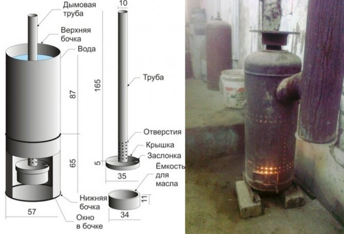
The principle of operation of the furnace on waste oil is about the same. It consists of two containers located one above the other, between which there is a combustion chamber with holes for air intake.Mining is poured into the lower tank, the vapors of which actively burn in the middle chamber, and combustion products, smoke and other substances enter the upper chamber connected to the chimney, from where they are removed naturally.
The hot water boiler is located at the top of the furnace. It is fixed, has taps for taking water in the bath and for starting the heating circuit. The steam room is heated from a brick wall that goes inside. In order for the effect of it to be maximum, it is necessary to make the distance from the furnace to the brick box rather small to reduce heat loss, but also sufficient for air to penetrate.
There is another option for manufacturing a structure for mining, combined with a brick oven. Only the bottom tank is made. The combustion chamber has the shape of a knee, smoothly curved at 90°. A vertical plate is welded to the end, which will communicate with the internal (furnace) part of a conventional brick oven. The incandescent gases formed during the combustion of mining enter the brick oven and heat it.
The further design is no different from the usual one: a water boiler is installed, a heating circuit with natural or forced circulation, shutoff valves, and so on are connected. Such a compact option is optimal for those who already have a finished furnace and only want to adapt it for burning mining.
The best option: creating a closed heating circuit with a hot water mixing unit. The heat carrier is heated in a heat exchanger installed inside the boiler or, alternatively, on the chimney.Such a system allows you to cut off the media from the water for household needs, provide a more uniform temperature in the system and makes it possible to fairly accurately adjust the temperature in the premises.
The opportunity to save money on the most costly area is very attractive to any homeowner, and the integration of all elements into a single system contributes to more convenient and efficient management of home heating. In addition, the process of recycling waste oil is difficult, and the ability to burn it with maximum benefit will be the best option for processing unnecessary substances.
Safety regulations
A potbelly stove at work with additional devices requires careful attention.
In order not to damage the equipment and not harm the room, you need to remember a few rules:
- Do not leave the device unattended for a long time, such as overnight.
- Before use, it is better to concrete the place under the furnace.
- Cover the walls with non-combustible materials.
- Do not place the device in a draft so that the fire does not spread to combustible materials. At the moment of ignition, the flame burns strongly and breaks through the holes in the pipe.
- Until the oil vapors begin to burn, it is impossible to add it.
Instructions for using the oven
Before the first test, you need to make sure that the unit is stable. Sequencing:
- fill the lower container with fuel to 2/3 of the volume;
- pour a little gasoline on top;
- open the damper;
- light a match and light a wick, a newspaper;
- wait until the gasoline heats up the oil and the vapors begin to burn;
- close the damper when the room warms up.
Oil consumption with low combustion will be about 0.5 liters per hour. With strong burning - 1.5 liters per hour.


The design and principle of operation of the heating device
It is based on the principle of operation of kerogas. This is a heating device that uses kerosene and air vapor to generate thermal energy.
The heater consists of the following blocks:
- Lower compartment. Welded from 4 mm sheet steel. Definitely has a round shape. Air enters through the damper, which is needed for the combustion process. If the door is completely closed, the burning will gradually stop.
- Cover with a hole.
- Middle compartment. This is a perforated pipe. Holes are needed for unrestricted air flow. For the manufacture of this and other parts, metal 5.5 mm and thicker is taken.
- Upper compartment.
- Chimney. Serves for removal of products of combustion. Pipe length - from 4 meters, optimally - 5-7 meters. Inclined sections up to 45 ° C are allowed, which increase the efficiency of heating equipment. But the greater the slope, the more soot will settle. There should be no horizontal sections, the upper part is directed only vertically. For the manufacture of this part of the furnace, fireproof materials are taken - tin, copper, stainless steel. The chimney is installed in the upper part of the body. It is desirable that it is separated - this simplifies maintenance.
The parts are welded together with a continuous seam.
Scheme of the furnace
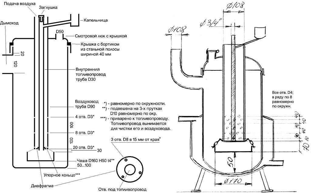
The heating efficiency is increased by the blower system. Also, small pipes are welded to the upper part of the pipe connecting the upper and lower chambers. This increases heat transfer, and the upper chamber heats up less. Also, vertical ribs are sometimes welded onto the upper module.
The setup works like this. Oil is poured into the lower compartment, and set on fire with the help of a wick. After the upper layer boils, steam lights up.Turbulence is created, replacing the throttle and swirling the gases. So burning vapors enter the perforated one, where oxidation occurs under the action of oxygen. In this chamber, the temperature reaches 800°C or more. Nitrogen becomes more active than oxygen, many toxic compounds of nitrogen and carbon appear.
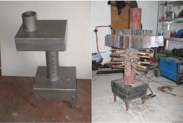
Standard and upgraded furnace model with welded fins and tubes
In the upper part, the pyrolysis residues are finally burned out. Here the temperature drops sharply, nitrogen loses its activity and is displaced by oxygen. Therefore, harmless nitrogen gas, steam comes out of the heating device, solid compounds of carbon monoxide partially settle inside the chimney.


