- How to connect a single-gang light switch
- Device
- Symbol
- Top or bottom input
- Types and types of switches
- Key switches
- Drawstring Switches
- Types of switches
- Switches with built-in motion sensor
- The principle of operation of switches with a motion sensor
- Remote switches
- The principle of operation of remote switches
- Video: remote switch
- Touch switches
- Video: touch switch
- Connecting the switch to the network
- How to connect the machine in the switchboard?
- Which is correct: top or bottom
- Sequence of correct connection of the machine
- Common mistakes
- Batch Switch Purpose
- Control of two lighting systems from three places
How to connect a single-gang light switch
Scheme for connecting a single-key switch to a light bulb:
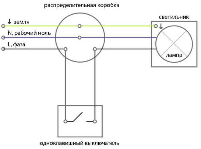
The circuit itself consists of one, two or more lamps that are connected in parallel. Also, this circuit resembles the circuit for connecting a pass-through switch.
In fact, how the wires are located does not really matter. They can be located inside the wall itself or be on the surface. An exterior switch in the apartment is recommended if a high-quality repair has recently been made and there is no need to destroy the walls and the need for wiring channels.
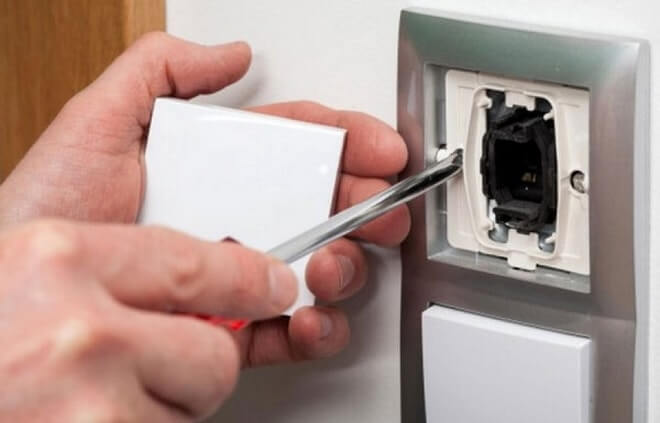
There are several ways to mount a single-gang switch. Here is an option for mounting an external single-gang switch.
As a rule, one more device is located under the switch - a socket or "socket with grounding". With this in mind, collect the cables of these devices in one corrugation.
- In order to check the absence of voltage in the cable, it is necessary to use an indicator screwdriver. After carrying out all the necessary manipulations to turn off the power, it's time to start installing the switch.
- It is necessary to get the switch by hand.
- After that, it is necessary to remove the working mechanism for closing / opening the electrical circuit. It does not have special springs, legs or holders. With that in mind, taking it off is pretty easy.
- Then you need to decide where the switch will be mounted. After that, you need to put points on the wall for installing fasteners. To do this, you need to take an empty case and attach it to the wall.
- Now you need to level and then apply with a marker points for drilling. After that, using a drill, you will need to make holes for fasteners. You can also choose an alternative mounting method.
- Now you need to remove the elastic plug from the switch housing. It is usually on top. Then it must be brought into the hole of the wire, then carried out to the end of the corrugated pipe. This pipe usually starts from the ceiling.
- In total, a neat and tight connection of the corrugation with the body should come out. He must have open access to the wires for further work.
- Now you need to connect the switch. At the end of the wires there is an insulating material (8-10 mm). It needs to be cleaned up.
- After that, a white wire must be connected to the terminal (marking L). The blue wire is connected to another terminal (marking 1).
- The wire that leads to the outlet must be laid in the bypass of the working unit. Then you need to bring it into the hole in the case from below. Insert the second end of the corrugated pipe into the same hole.
- Now you need to put the switch back together. To do this, put the front panel in place, and then fix the key.
The final step is to test. To do this, you need to turn on the power supply and press the key a couple of times. If the device lights up after turning it on, everything is done correctly.
Device
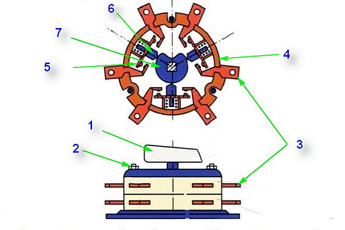
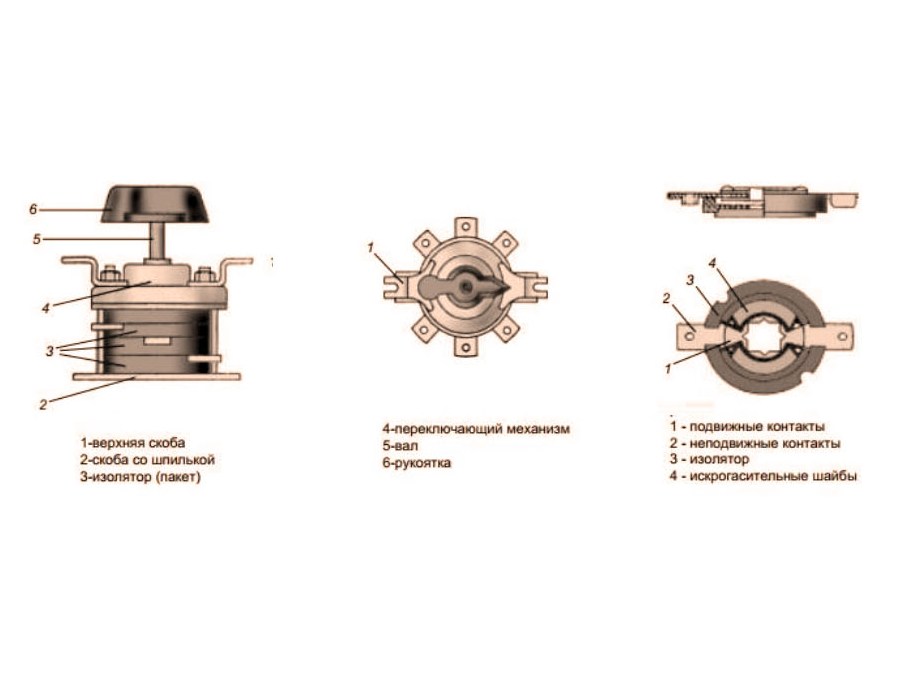
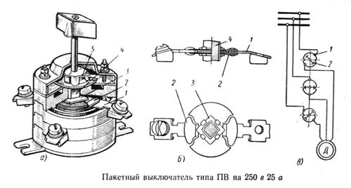
The package switch consists of the following main parts:
- corps;
- contact system;
- switching mechanism;
- handles.
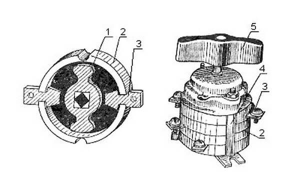
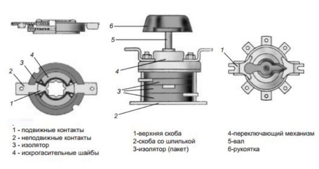
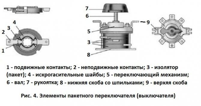
Package switch device
The body is made of carbolite, silumin or durable and self-extinguishing plastic. The contact system consists of fixed and movable sections. The fixed section has 2 screws to which the power wires are connected. Movable contacts - springy, have spark arresters. Sections are assembled on a special pin, with which they are attached in the right place. The pin is equipped with a handle for carrying out the necessary manipulations manually.
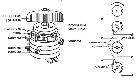
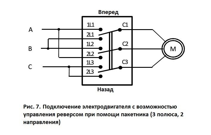
Principle of operation - the product can only perform the function of switching on and off, and may have intermediate positions for various operations. For example, when starting an asynchronous motor at a certain position of the handle, power will be supplied to it, it will be connected to a star, a triangle, according to a double star scheme, or even be de-energized.To turn the bag into operation, you need to turn the handle to a certain mark, there are corresponding marks on the body. This allows you to fix the moving contacts in the desired position. For this, a spring mechanism is used.
The package switch provides disconnection of the object from the el. mains, but the power supply itself cannot be disconnected.
Best of all, their labeling will tell about the types of bags.
Symbol
Symbol structure:
G P X X – XXX XX XX XXXX X
1 2 3 4 5 6 7 8 9. where:
- hermetic (D) without a letter - the usual design;
- batch (P);
- switch (B), switch (P);
- number of poles (from 1 to 4);
- the value of the rated current in amperes (6.3; 10; 16; 25; 40; 63; 100; 160; 200; 250; 400);
- conditional designation of the number of directions (H2 - in two directions; H3 - in three; H4 - in four; P - for engine reverse);
- climatic version and category of placement (U2; U3; U4; T2; T3; T4; HL2; HL3; HL4; UHL2; UHL3; UHL4);
- degree of protection and case material (IP00 - open version; IP30 - protected version; IP56 strong and IP56 square - sealed version, where strong - silumin case; square - plastic);
- fastening method (1 - front bracket fastening with installation behind a panel up to 4 mm thick; 2 - front bracket fastening with installation behind a panel up to 25 mm thick; 3 - back bracket fastening with installation inside the cabinet; 4 - fastening by the body (only for products with degree of protection IP30 and IP56).
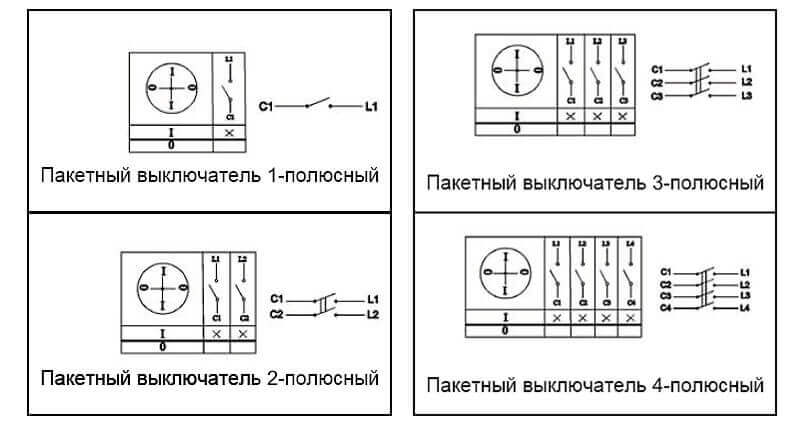
Conditional graphic designation batch switches on electrical diagrams
From this symbol, you can clearly see what packets are.This symbol is indicated in the passport for a specific product, its body and in the relevant technical documentation.


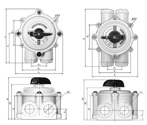
The appearance of the package sealed switch
Top or bottom input
A very important question that worries both many electricians and just home craftsmen: how to connect the machine, from above or below? To answer it, you will have to refer to the regulatory documentation, namely, the Rules for the Construction of Electrical Installations.
Paragraph 3.1.6 states that the machine should be connected to the mains from the side of the device from which there is a fixed contact. This means that the voltage in a single-phase or three-phase network must be on the side of the switch that does not break the electrical circuit. Item 3.1.6 applies to many types of switching technology. It can be not only a single-contact, but also a two-pole or three-phase machine, as well as a differential bag or RCD.
You can find out the location of this contact only by disassembling the bag, which is not very convenient with each replacement in the apartment. But the design of all machines is almost the same, so you should find out where the fixed contact is on only one switch. And it is located on top, respectively, the connection of a single-pole or two-pole machine must also be performed from above.
If, however, a bag of an unknown manufacturer was in the hands, then just look at its case, or rather, the front panel. In this place, most often all the necessary information is applied to the machine, such as the model, accuracy class, and the connection diagram of the circuit breaker with the exact location of the moving and fixed contacts.
Conclusion: the circuit breaker must be connected to the mains from above. This is what the regulations say to avoid unnecessary confusion.
But if you look from the technical side: is there a significant difference in connecting the power cable? Answer: no, it does not matter at all from which side the operating voltage is applied to the bag. The device will work properly both with a connection from above and from below.
Types and types of switches
Switches are divided: by type, type, each type has its own uses. And just in the table below, we see their division according to the degree of protection.
At the moment, the international protection system (International Protection) IP is widely used. These letters are followed by two numbers and an optional letter.
Degrees of protection of circuit breakers
The first digit indicates that the product is protected from foreign objects entering it. These objects are of any size, up to the size of dust particles. The second digit usually indicates the degree of protection from moisture. It has a correlation dependence: the larger the number, the higher the degree. Switches differ in the way of switching - they can be with screw or screwless terminals. In the case of screw terminals, the wires are clamped between the plates with a screw. However, there is one minus in this connection - over time, there is a high probability of loosening the contact, so you have to periodically tighten the screws. The screwless clamp makes the installation work much easier and, due to the design of the mechanism, reliable contact of the wire with the conductive fittings is ensured.
Key switches
The switches consist of contacts fixed inside the housing and a rocking mechanism, preloaded by a spring. Key switches can be divided into two variations:
Switch types
- With the use of a ball that, when a key is pressed, begins to move along a rocking rocker. Passing the axis, it rolls over the shoulder of the rocker, thereby moving the mechanism with contacts in the other opposite direction.
- Type of switch using a spring frame. Since it has the ability to swing on its axis, it thereby breaks or creates an electrical contact.
Regardless of the type of devices, the equipment is turned on and off by pressing a button. Such switches, when properly maintained, are characterized by a long service life of several decades. And yes, they are low cost. On the market, you can find designs of various types: there are lighter ones, there are more complex ones - when two or more keys are fixed on one base.


Drawstring Switches
This version of the era of the last century is ideal for sconces, table lamps and other lamps. Since their main feature is the presence of a strong cord that comes out of the switch body. Actually turning on and off this item occurs precisely due to this lace. Fixed on the lever, it, in turn, interacts with a moving contact block. By releasing the cord, you thereby straighten the spring fixed in the body and the block returns to its original place. The unusualness of this type is manifested in the modification - the control of two or more light bulbs. They respond to the amount of pull on the cord.
At the first pull, one of the lighting units is turned on, at the second, the next one, and so on. Shutdown occurs in reverse order.
Types of switches
Switches are manually operated switching devices and are used to turn lights on and off. They have different designs and functions, which led to their division into types.
Switches with built-in motion sensor
Switches with a motion sensor are mainly used on flights of stairs and when creating street lighting networks. They are quite easy to use: in order to start using these devices, it is enough to install and configure them according to the instructions.
The appearance of switches equipped with a motion sensor may differ, but functionally they are very similar
The basis of switches with a motion sensor are electronic components that constantly analyze changes in the level of illumination of an object (apartment, street or house), as well as any movements in the zone of operation of the sensor.
The principle of operation of switches with a motion sensor
The operation of a motion sensor switch is based on the continuous scanning of infrared (IR) radiation, covered by the field of view of the sensor (sensor), which is usually made of pyroelectric materials. Basically, these switches have a wide viewing angle and are installed on ceilings. In addition to monitoring the presence of living objects, they have the ability to change the intensity of lighting, and can also be used in various internal security systems.
The switch sensor turns on the lighting when moving objects appear in the zone of its action
Remote switches
The remote switch is a set consisting of a compact control unit and a remote control (there may be several). The device itself is quite similar in appearance to a simple flat-type switch. A distinctive feature of the remote switch is the ease of installation, since in order to install it, it is not necessary to carry out preparatory work (strobe or drill walls), carry out hidden wiring. It is enough just to find a convenient place, take a few screws and double-sided tape and attach the device.
Installing a remote switch does not require complex electrical work
The principle of operation of remote switches
The operation of remote sensors is based on the principle of reception / transmission. The user presses the power button on the remote control, thereby creating a radio signal, which then receives a relay that closes or opens, depending on the command given from the remote control, a circuit in phase that is supplied to the light source. Depending on the state of the circuit, the light turns on and off. The coverage area directly depends on the design features of the dwelling, as well as on the materials that were used in the construction. In general, the coverage area of remote sensors is from 20 to 25 m. The transmitters are powered using conventional 12 V batteries (usually enough for 5 years).
Video: remote switch
Touch switches
Small and compact devices constructed from multiple touch panels for ease of use.In order to use the switch of this type, it is enough to touch its screen once.
Touch switches operate with a light touch of a finger
These switches include:
- touch panel (an element that responds to touch and initializes the sending of a command for further processing);
- control chip (engaged in processing and converting the command);
- switching part (provides power switching).
Due to the use of electronic components, it is possible to remotely control lighting devices and connect additional elements: motion, temperature and light sensors.
Touch switches can be equipped with a remote control
Video: touch switch


Before purchasing a switch of one kind or another, you should familiarize yourself with the selection criteria, which will be described below.
Connecting the switch to the network

We recall that the switch is installed to break the current-carrying wire. The "0-th" wire always comes to the light bulb from the junction box. The wires are connected in a certain order:
- cut up to one centimeter of insulation from the wire;
- on the back of the switch, check the connection diagram;
- insert the stripped wire into the contact hole between the clamping plates and tighten the clamping screw;
- check the reliability of fixing the wire (the wire should not swing);
- make sure that a bare vein is visible from the contact no more than two millimeters;
- insert the second wire and secure it;
- unscrew the bolts of the spacer mechanism and insert the switch into the cup holder of the wall, align and fix it along its horizon;
- fix the switch in the cup holder of the wall and check its fixation;
- install the protective frame and fix it with screws;
- install the on/off switch in its place.

Work on connecting switches, switching the electrical network does not require great physical strength, but it is imperative to follow the rules of electrical safety and switching elements of electrical circuits.

How to connect the machine in the switchboard?
Replacing a circuit breaker or installing a new one belongs to the category of operations that, with proper skill, take 5-10 minutes. But in order for the home electrical network to continue to function properly after replacing the bag, you need to know how connect it correctly. Most often, the connection of the switching device occurs in the switchboard.
Which is correct: top or bottom
An important question that is asked by many newcomers to electrics. After the circuit breaker is securely fixed to the DIN rail, power should be applied to it, but not everyone knows whether to connect the power wire from above or below.
To resolve this issue, it is necessary to refer to the technical literature, which is the primary source of information - the rules for the installation of electrical installations.
The PUE contains clause 3.1.6, which states that the operating voltage must be applied to the fixed contact of the circuit breaker.
But in order to find out which of the two contacts is fixed, the bag needs to be disassembled, or rather, the side cover must be removed. The opened device of the machine shows that the lower contact is movable, and the upper one is fixed. This means that the supply wire is connected from above, and the wire going to the consumer is connected from below.
Sequence of correct connection of the machine
Armed with a flat and shaped screwdriver, crimping tips, a press and a fitter's knife, you can proceed with the installation of the circuit breaker:
- Fix the DIN rail in the switchboard using two texts - special metal screws. It should be clarified that in many modern switchboards a DIN rail is installed initially.
- Insert the machine with grooves into the specially provided DIN-rail mounts and snap the latch on the bag body.
- Remove voltage from the supply wire, strip its end from insulation with a fitter's knife, put on and crimp the tip, the diameter of which corresponds to the cross section of the wire.
- Using a screwdriver, unscrew the fixing bolt on the upper fixed contact. Insert the wire end into it and tighten securely. Check the quality of the connection by gently moving the wire from side to side.
- Fix the wire going to the consumer from below.
- Turn on the circuit breaker and check the operation of the circuit.
When the automatic machine is connected from below, the network will continue to work, but the arc that occurs when the bag is turned off may be too large, which will significantly reduce the life of the product.
Common mistakes
Do not connect stranded wires without special crimping lugs. This will lead to a gradual weakening of the contact, sparking and, soon, the failure of the circuit breaker.
Figure 2: Correct wire crimping
Also, it is impossible to clamp two or more wires of different sections at the input of the machine.The contact will qualitatively fix the wire of a larger cross section, and the second conductor will not be fixed enough.


The result is the same as in the previous version - sparking and failure of the bag. To prevent this from happening, you should use crimping tips.
Some electricians believe that a stranded wire can not be crimped, but simply soldered with high quality, but this is not so. Even the highest quality soldering “drains” over time and the contact becomes weaker. A very poor contact can cause a fire and permanent damage to the circuit breaker. Therefore, it is best to use tips and a special press.
Batch Switch Purpose
Such a mechanical switch as a packet switch was intended to turn off electricity in apartments. It was directly connected to the network, so disconnecting from the network without removing the voltage from the entire electrical panel was not possible.
The design features of this PV (batch switch) have such disadvantages as rapid wear of the contacts of the bag due to free access of dust to the switch contact areas. Exposed power cords can cause electric shock.
The fragility of the package, designed for a little over 100 switching. PVs were intended for switching small currents in networks up to 660 V. A bag was installed in all electrical panels, control panels in the form of an introductory switch. The package switch device consists of an insulating material with installed moving and fixed contacts, which are also insulated.
Batch switch, two-pole-PP
Terminals for fastening wires are on fixed contacts.The principle of operation of the batch switch is that the manual mechanism must be turned 90 to turn it off or on. Thanks to the spring mechanism and the locking protrusions, the contacts are clearly fixed in the desired position.
Package switch device PV-2-16
Batch switches can be open, in a protective or sealed case. Explosion-proof package switches were also used. PV can only be installed in dry rooms in the absence of dust, in electrical panels, boxes where there is no possibility of open contact and in non-flammable rooms.
Designations on the switch housing
The package switch device of protective design has a housing made of insulating material. Sealed PV housings protect the switching mechanism from moisture. Such package switches are designated according to the scheme PP - package switch or PV - package switch. The numbers indicate the number of poles and the rated current of the bag.
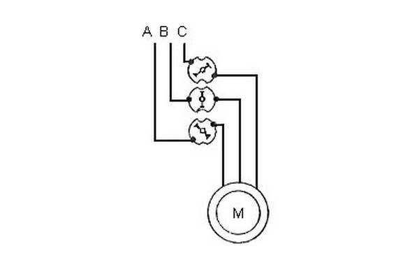
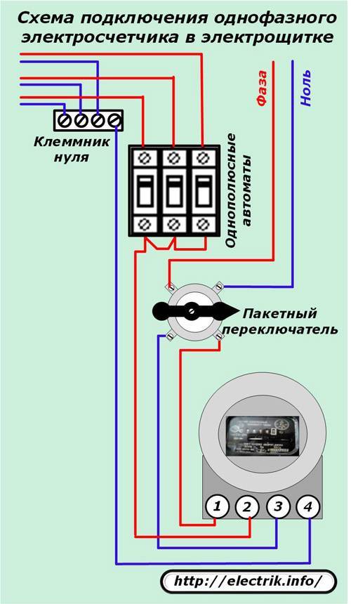
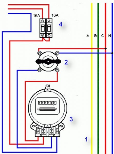
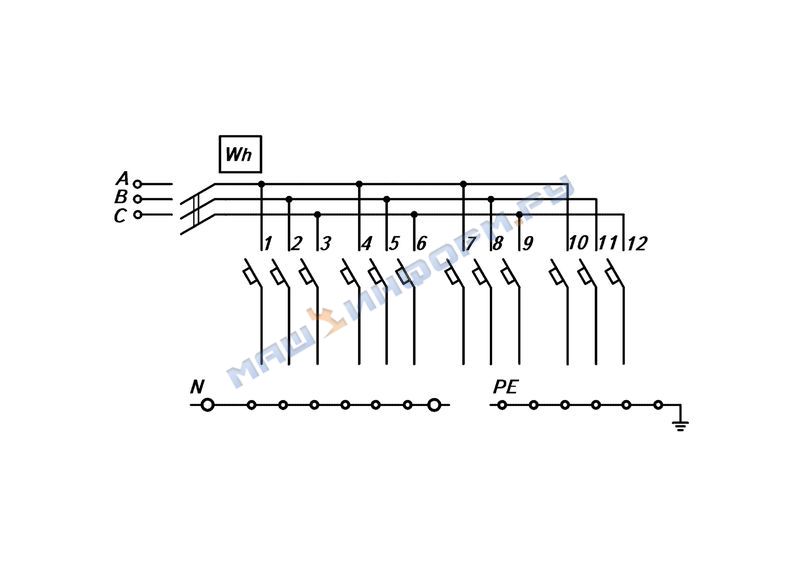
Batch switch wiring diagram
Package switches and switches have several types of fastening - this is fastening to the front panel 4 mm or 22 mm, where the mains wires are fastened at the back, fastening with a back bracket and fastening to the package body.
The number of contacts can be different depending on the use of the supply voltage for single-phase (two-pole) or three-phase (three-pole) voltage. Now such bags have remained in Khrushchev, where, as they fail, they are changed to circuit breakers with full protection.


Control of two lighting systems from three places
The two-gang switch through passage is cross. It is installed as a kit.That is, it also includes two two-key limit switches, if you want to control the lighting from three points. It will have 4 inputs and 4 outputs.
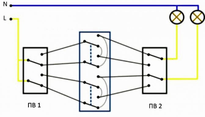
Installation is carried out as follows:
- For mounting the circuit, a standard box with a diameter of 60 mm is not enough. Therefore, its size should be larger. Or you need to sequentially install 2-3 pcs. ordinary.
- 12 wire connections are made for connection. This will require laying 4 three-core cables. Here it is necessary to correctly mark the cores. 6 contacts are suitable for two limit switches, and 8 for a cross switch.
- A phase is connected to PV1. After you need to make the necessary connections. On the back of the device is a diagram of a two-key pass-through switch. It must be properly combined with external connections.
- PV2 is connected from lamps.
- Four PV1 outputs are connected to the inputs of the cross switch, and then its outputs are connected to 4 PV2 inputs.


