- What does a lathe consist of: main components
- bed
- Lathe support
- Do-it-yourself headstock of a lathe
- Tailstock lathe
- Making a do-it-yourself tool holder for a lathe
- What other types of machines can be made?
- Turning and milling
- With copier
- Mini
- From an electric drill
- From the washing machine motor
- What is a lathe made of?
- Lathe support
- tailstock
- Do-it-yourself manufacturing features of the front headstock of a lathe
- How to make a do-it-yourself tool holder for a lathe
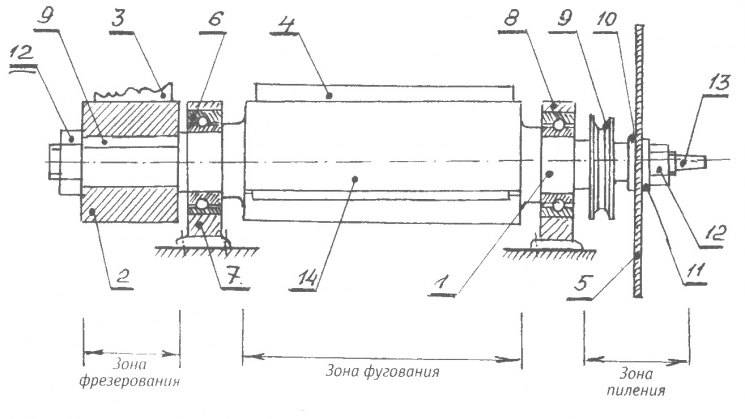
- Design features of the cutting machine
- Classification according to the method of feeding the cutting element
- Instructions for making a simple do-it-yourself lathe
- Machine tools for metal processing
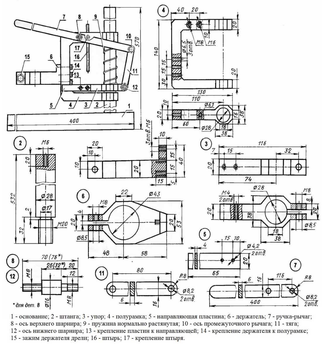
- Design and dimensional drawings
- And what, in fact, are we talking about?
- Motor or angle grinder?
- About speed control
- About the name
- And what, in fact, are we talking about?
- Motor or angle grinder?
- About speed control
- About the name
- Conclusion
What does a lathe consist of: main components
For the most part, industrial and household lathes are similar. The difference lies in functionality, power and weight. The figure below shows the device of a typical screw-cutting lathe. The main nodes are:
- bed;
- caliper;
- headstock (placement of the gearbox to adjust the speed of rotation and change the amount of torque);
- tailstock (for more stable and reliable support of the workpiece or part clamped in the chuck (spindle), as well as for installing drills, taps and other tools);
- tool holder.
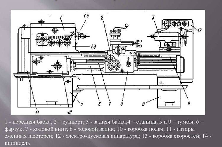 Screw-cutting lathe device
bed
One of the main elements is the frame - a massive metal base on which all the main components and parts of the equipment are mounted. It must be strong enough, and the mass must be such as not to allow the machine to tip over during operation. For the floor version, massive supports (pedestals) are added.
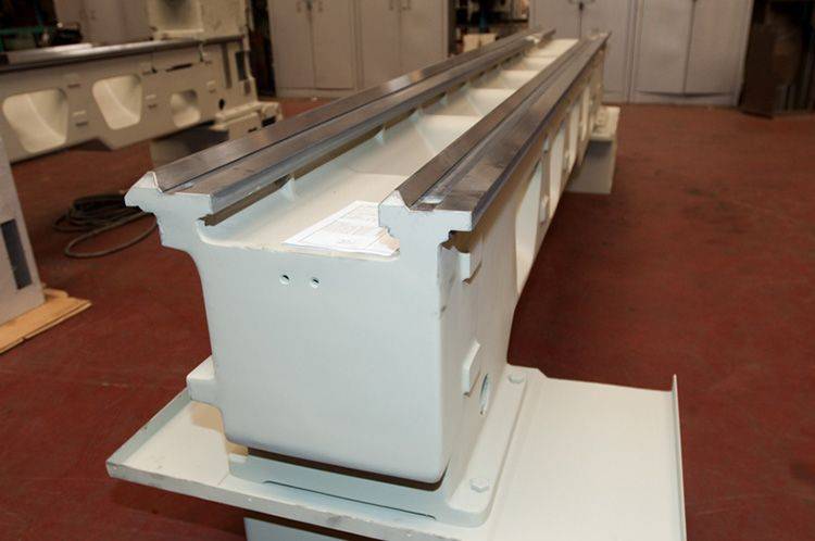 lathe bed
Lathe support
The lathe caliper is designed to move along, across and at an angle to the axis of the spindle of the cutters fixed in the tool holder. The device has a cross structure, consisting of three main elements: carriage, transverse and incisal sleds.
 Metal lathe support for home
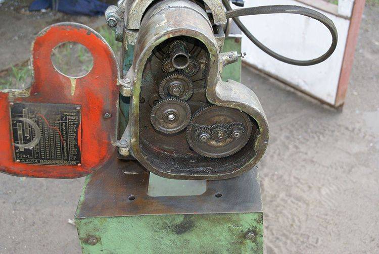
Do-it-yourself headstock of a lathe
The headstock is one of the more difficult components of a lathe, especially for self-production. It contains a gearbox with a spindle and a control unit. Under the casing of the headstock is an electric motor, which is connected by a belt drive to the gearbox pulley.
 Homemade headstock assembly with cartridge
This unit contains a block consisting of interchangeable gears designed to transmit and change the spindle speed and torque from the feed box shaft. You can buy a lathe headstock or make your own.
 Lathe guitar
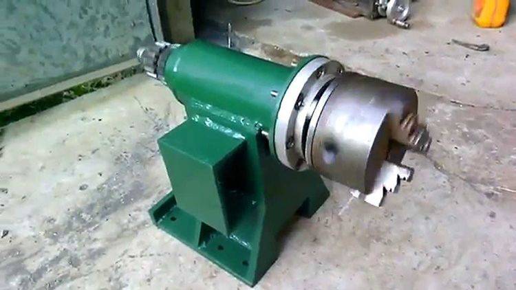
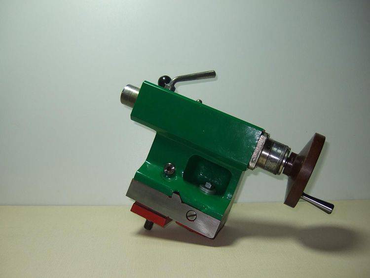
Tailstock lathe
The tailstock of a metal lathe is movable and is designed to press the workpiece to the center of the spindle. One of the elements of this assembly is a quill, on which a fixed or rotating center is installed, resting with its tip against the workpiece. The workpiece is installed in the chuck on the spindle and supported by the tailstock. Thus, reliable fastening of the part for its high-quality processing is ensured.
 Tailstock lathe for metal
Drills, taps, reamers, etc. can be installed in the tailstock. When installing and moving on the skids of the frame, it is necessary to avoid sharp and strong impacts on the body of the unit in order to prevent displacement of the centers.
 Tailstock detailing
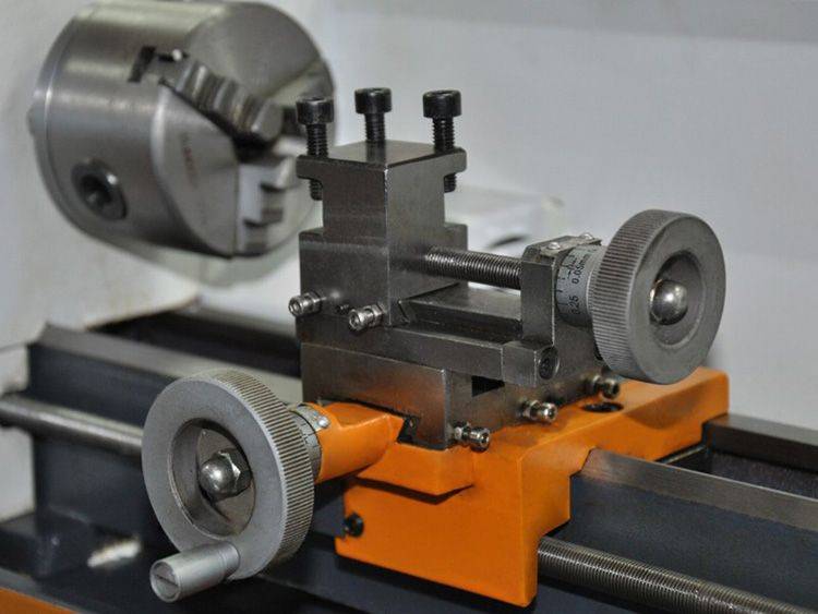
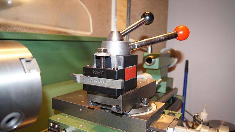
Making a do-it-yourself tool holder for a lathe
The tool holder is intended for fixing a metalworking tool on the support of a lathe and moves both in the longitudinal and in the parallel direction relative to the workpiece. There are two types of tool holders: two- and four-position. In the first case, two cutters can be installed simultaneously with screws, and in the second, four, which allows you to quickly change the cutters if necessary without stopping the lathe. For quick change of incisors, a special handle is provided.
 Metal lathe holder
What other types of machines can be made?
Before creating your own lathe, you should study those varieties of it that were invented by many interested people. Among the machines, both home-made and factory, the following types are distinguished.
Turning and milling
Such a machine is already a powerful modification of the previous versions of machines.Most often, the turn-mill machine is equipped with a CNC, because it is extremely difficult to manually control the router with high accuracy. However, such a machine has the right to exist and is widely used in domestic needs. Its design consists of:
- Beds.
- Electric motor to rotate the headstock.
- A hand mill placed on guides, which ensure its movement along the axis of rotation of the workpiece.
With copier
A lathe is necessary when creating a large number of identical products, most often you can hear about dishes and balusters for stairs.
There are several options for making a copy lathe: with a milling cutter, with a circular saw and with a chisel. All of these methods involve the use of patterns. A template is a profile of a future product, which is cut out of plywood of small thickness.


A handrail is attached along the lathe along the entire length of the workpiece. A pattern is mounted behind the lathe. A cutter or cutter is attached to the handrail, the movements of which are regulated thanks to the stop coming from the cutter, cutter or saw to the pattern.
Thus, during the rotation of the bar, the cutting tool completely repeats the silhouette of the plywood profile with sufficient accuracy.
Mini
For many domestic needs, it is not necessary to create an aggregate of impressive dimensions capable of rotating a log with a radius of 300 mm. Sometimes a machine with an extremely simple design is enough, in which the drive from an old tape recorder, powered through a power supply, can act as an engine. For the bed of such a machine, you can use a board 150 * 20 and long, which depends only on the needs of the craftsman.
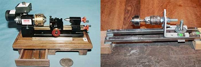
For such a mini-machine, a belt drive will be superfluous, so most often the headstock is mounted directly on the motor shaft.And as a faceplate, a head from a drill or a homemade chuck with three clamping screws serves.
The tailstock is made of a bar, in the center of which a hole for the shaft is drilled exactly at the height of the motor axis, in the role of which a dowel-nail can act. If you provide the machine with a power supply with adjustable output voltage, you can get the unit with a speed controller.
From an electric drill
An electric drill can be found in almost every home. The advantage of a machine driven by an electric drill is that there is no need to buy a separate engine. Drill-driven designs range from the most rudimentary, where the drill is clamped to a table.
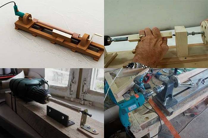
On the contrary, the tailstock is mounted using a pair of corners and a nail or a sharpened screw, to a more perfect one, in which the drill serves as a source of rotational force, but does not directly participate in the process of rotation of the workpiece. The second method protects the motor from overheating and failure during overloads.
From the washing machine motor
It is a standard scheme of a lathe with an engine, direct or belt drive, a bed and two headstocks.
When constructing a lathe from a washing machine motor, it must be remembered that the household appliance motor is designed to circulate with an unbalanced load, but this does not mean that the tailstock can be abandoned. Its presence is mandatory especially when working with a long and heavy workpiece. The device of such a lathe is easy to implement at home. For this you need:
Weld or bolt two steel pipes, at one end fix the engine from household appliances.Fix a bar between the pipes with the ability to move it along the frame, a corner of the handrest will be attached to it. On the opposite side, the tailstock is set up in accordance with the instructions above.
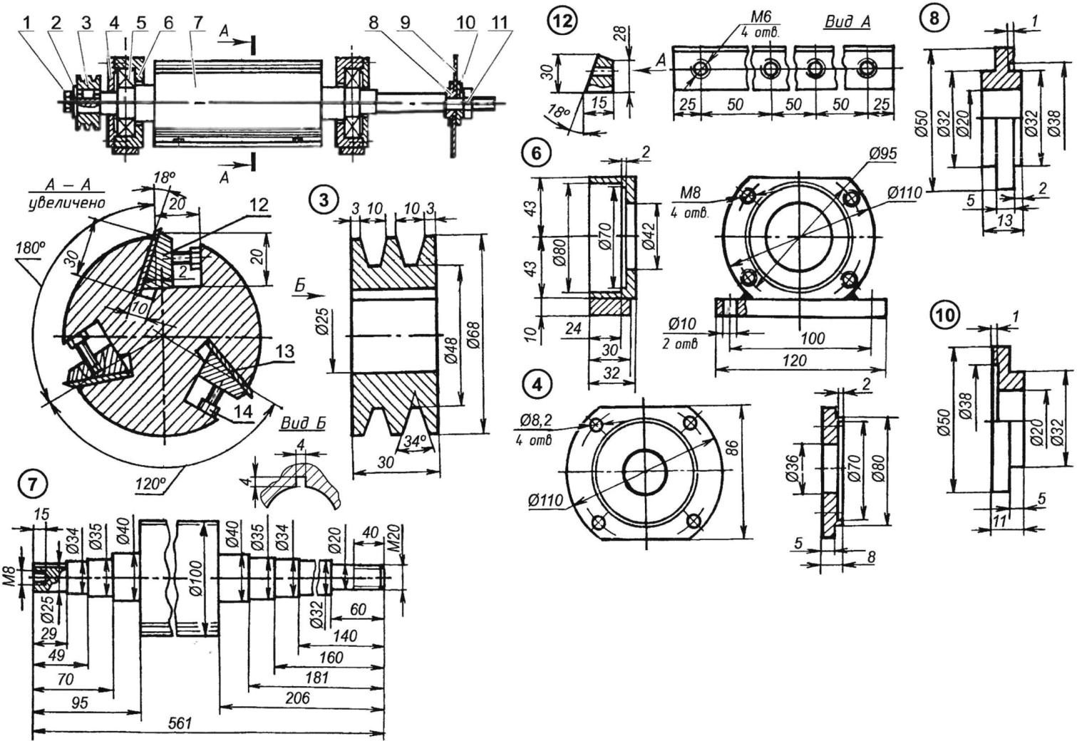
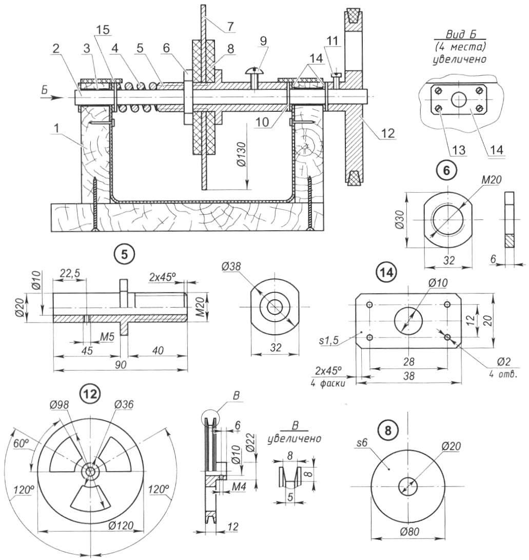
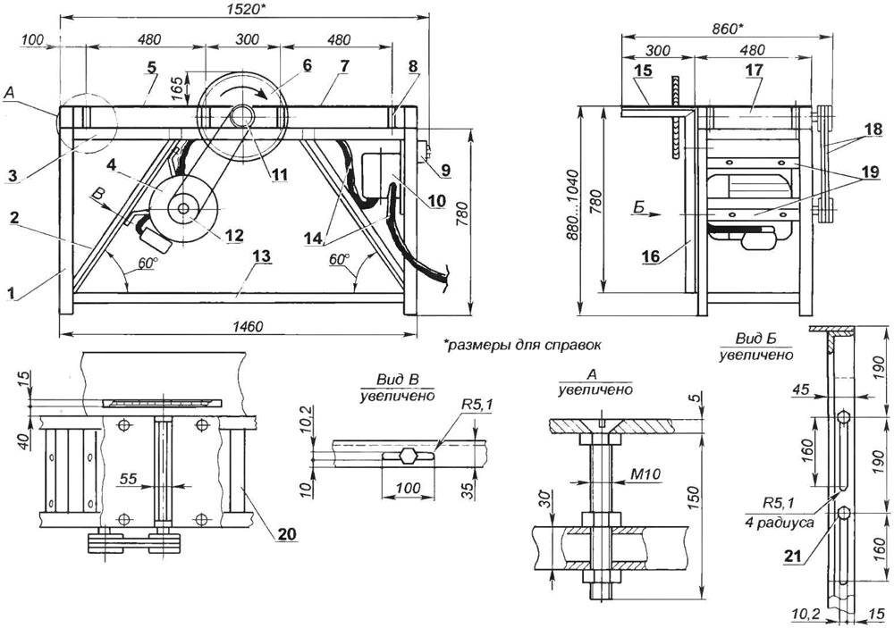
What is a lathe made of?
Typical design
Even a small lathe weighs a lot, creates vibrations during operation. A reliable frame (1) is needed, on which functional units and individual parts are fixed. If it is intended to create a floor version, use reliable supports of the desired length. The final height of the work area should be user-friendly.
The following list contains other components:
- A gearbox is placed in the headstock (3). It is designed to adjust the spindle speed (4), change the amount of torque.
- On the reverse side, the workpiece is supported by the tailstock (6). Taps, drills, and other tools are also installed here, if necessary.
- In the standard processing mode, the cutters are fixed in a special holder (5).
- This assembly is mounted on the caliper (8). For smooth horizontal movement, a screw mechanism is used, located in the apron (7).
- The feed box (2) drives the drive shaft.
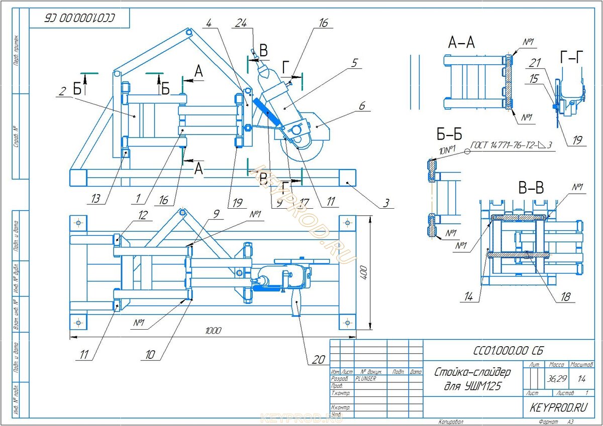
Lathe support
Device
Drawing notes:
- the carriage (1) and the entire block as a whole (17) are driven by the running shaft (2);
- the movement mechanism is connected with a special handle (15);
- these slides (3) provide freedom of movement of the upper part in the transverse direction (12);
- it is fixed on the rotary assembly (4) with longitudinal guides (5);
- the cutters are installed in the holder (6);
- screws (7/8) are used to fix this part / tools;
- the handle (9) can safely move the cutters at a distance from the working area;
- fastening element (10) of the upper part (11);
- for its precise movement in the appropriate directions, handles (13, 14) with a screw drive are used;
- handwheel (16) move the caliper manually.
In a detailed study of this part of the metal lathe, it is necessary to take into account the increased loads to which it is subjected in the process of performing technological operations.
Pay attention to the large number of moving components
Maintaining precision machining requires more than just durable parts. Constant adjustments will help eliminate play to compensate for wear. Damaged seals are recommended to be replaced with new products.


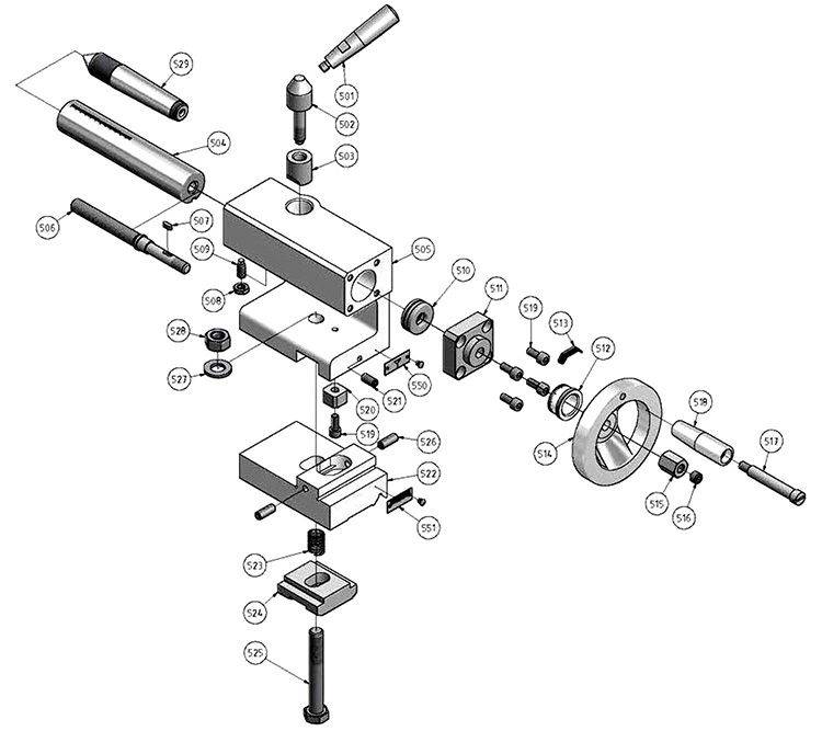
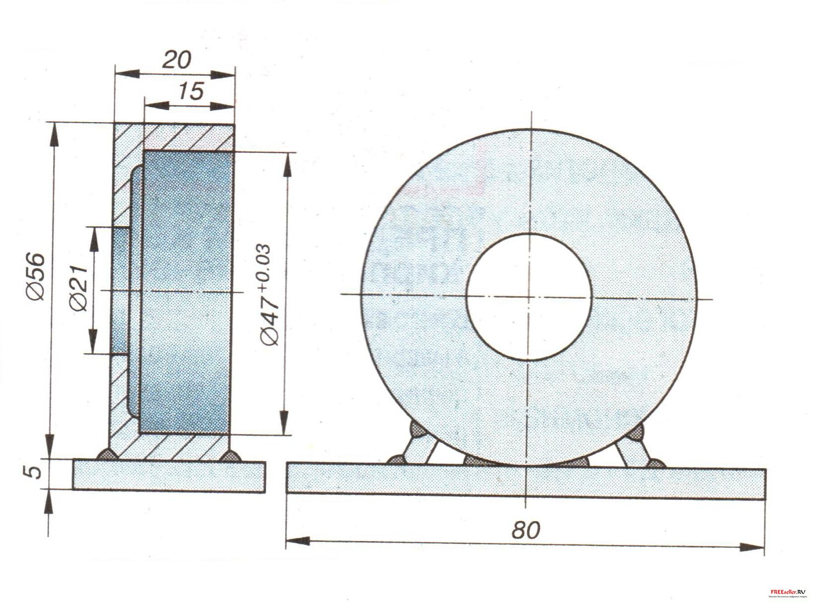
tailstock
The main components of the node
Here and below, we will consider simple for self-play projects with clarifying comments. The example in the figure is more suitable for woodworking equipment. In order to work with strong workpieces for a long time, a support shoe should be made of a steel plate.
In addition to the standard equipment, such interchangeable devices are useful
With their help, they expand the basic capabilities of the tailstock. In the author's recommendations, it is proposed to remove part of the standard cartridge mount (3). This will increase the working stroke of the tool, process larger workpieces.
Do-it-yourself manufacturing features of the front headstock of a lathe
For the manufacture of homemade products, simple design solutions are used.
A belt drive (1) is used here, which is distinguished by its low cost and low noise level. A double pulley (2) is installed for torque staging.To prolong the life of the spindle (3), a pair of ball bearings should be used. If necessary, holes are made in the body for periodic filling of lubricant.
As a rule, a metal lathe is equipped with three-jaw chucks
These clamps center automatically without further adjustment. Self-production of such nodes will cause difficulties. Therefore, this functional element of the headstock of a lathe can be bought in a store.
For processing square workpieces, models with four cams are used.
How to make a do-it-yourself tool holder for a lathe
It is better to make the main part of the holder in a collapsible version
This will allow you to make repairs without unnecessary difficulties. Screws are screwed into the threaded holes, which firmly fix the tool. The distance between the plates is determined taking into account the dimensions of the cutters.
A handle is installed on top to quickly turn the knot. This device allows you to quickly change the tool for complex sequential processing of workpieces.
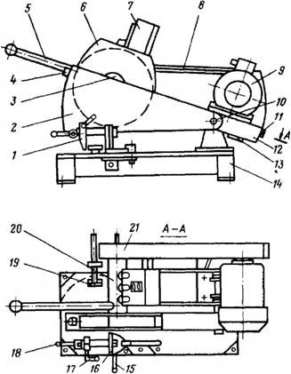
Design features of the cutting machine
In order for the machine to serve for many years, it must be made of reliable materials. Metal structural elements are best made from steel alloys, which are particularly hard. The operation of the finished equipment in this case will be smooth and stable.


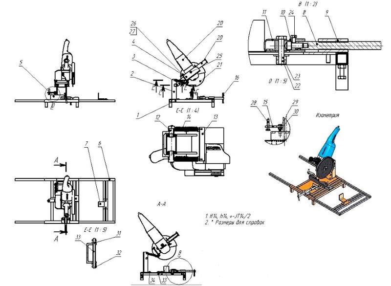


The platform is best made of heavy, rigid material - much here determines the subsequent position of the machine (whether it will be mobile or stationary).
To ensure reliable fastening of the workpiece to be processed, a more complex structure can be mounted by including a vise as an element in it.
The disc may have an abrasive surface if it is intended to treat the edges of the metal from burrs formed during cutting. It is convenient to process chamfers with such a disk.
When it comes to stationary devices, it is better to use a gear transmission. It guarantees connection reliability and good performance. The belt version is more suitable for mobile devices.
Classification according to the method of feeding the cutting element
There are a large number of machines on sale, before purchasing, it is important to understand how the cutting element feed system works. The cutting element can be fed in the following ways:
- frontal supply of the cutting disk;
- a device with the implementation of the lower feed of the cutting element;
- construction, the basis of which is the work of the pendulum method.
The metal base of the cutting machine can be floor standing or tabletop when using. In the first case, a larger diameter disc is installed, which allows cutting a larger volume of parts. Desktop equipment is more mobile, has a reduced weight.
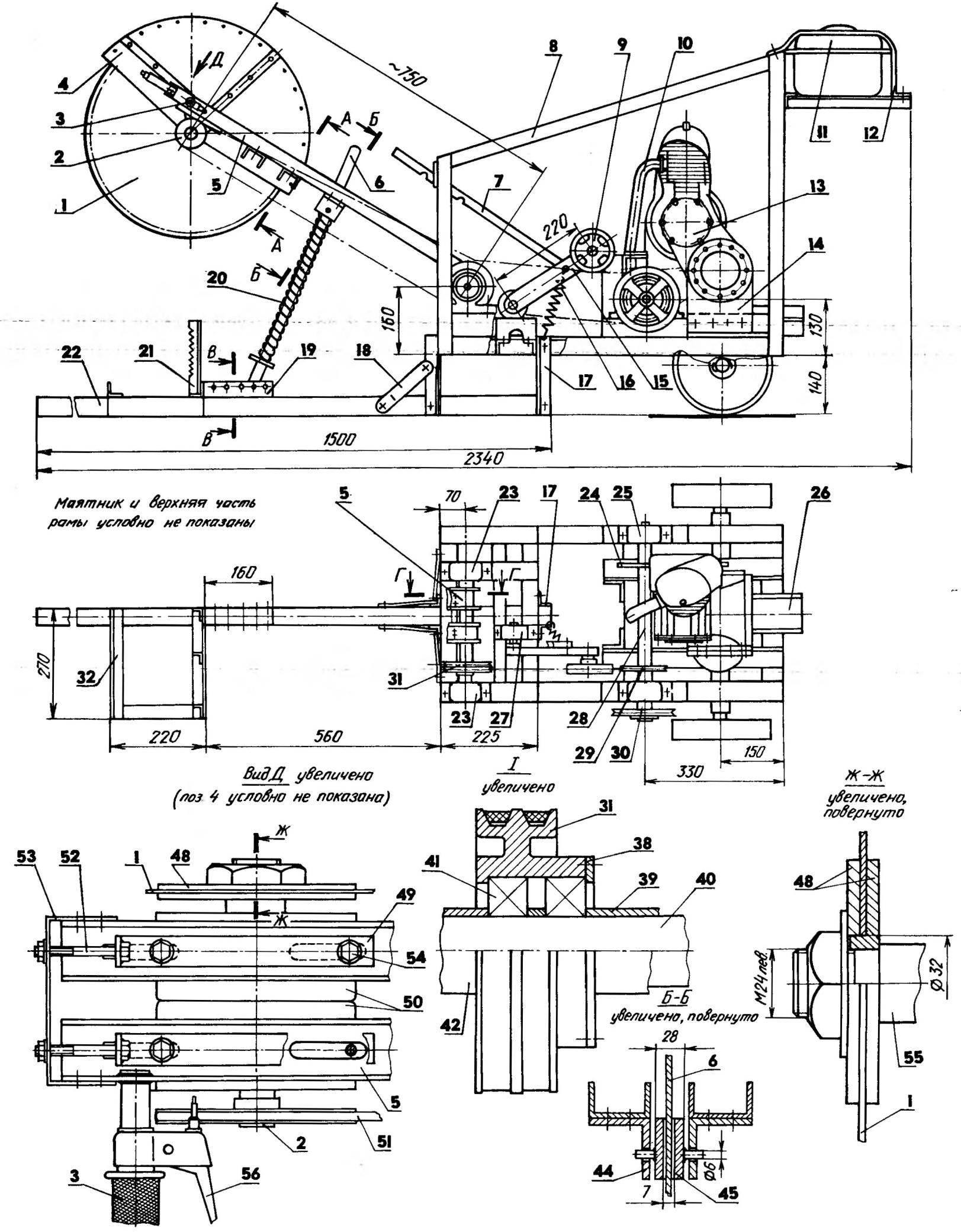
Instructions for making a simple do-it-yourself lathe
Since everyone decides what his lathe will look like and what dimensions it will have, it is impossible to give an accurate description of the manufacture of all parts with dimensions, tolerances and fits. However, the process of building any lathe consists of the same steps.
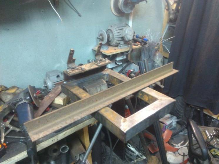
Frame manufacturing. As mentioned above, it is impossible to make a massive cast-iron frame at home. Therefore, its role will be played by a frame made of a channel or steel profile pipes, which are cut to size and then welded according to the drawing
It is important to observe the correctness of all right angles, so control with a square should be carried out every time the next joint is made. Works best on a flat, horizontal slab
This will make it possible to obtain a frame with strict geometry in the horizontal plane. You can do without a massive bed, making it from long shafts as guides.
On a lathe, side racks of the bed are made.
Assemble guides with racks. In this case, distance bushings are installed between the side support elements.
Bushings for attaching the tailstock and tool holder are mounted on the guides. It is not necessary to make them the same length. One piece can be made shorter than the other by using the long piece as a guide and the shorter piece to support the moving parts. This solution will increase the working stroke of the rear center.
From a steel sheet with a thickness of 8 - 10 mm, the mounting sites for the quill and caliper are made and fastened to the guide and retaining bushings using bolts with a diameter of 6 mm
Particular attention should be paid to the mounting holes, since the slightest inaccuracy will lead to distortion and jamming of the moving parts of the machine.
Install lead screw. You can carve this part from a workpiece or use a threaded part from any device, for example, from a high chair with variable height
Be sure to make sure that anti-friction bushings made of bronze or brass are installed in the corresponding holes in the side racks.
A vernier and a steering wheel are attached to the lead screw.
A platform for attaching the headstock is installed, after which the assembly of the frame is considered complete.
From the bearing support, two ball bearings, the main shaft with pulleys and the spindle, the headstock is assembled.
A tailstock is made from a long screw, a sleeve with an internal thread, a metal profile and a handle, after which the rear movable assembly is mounted on the machine.
Control and, if necessary, adjust the alignment of the front and rear centers.
Assemble the support. The process of its manufacture is similar to the assembly of the frame - the guides are equipped with bushings, a screw, a vernier and a small steering wheel are mounted.
A tool holder is made from a thick metal plate and bolts with a diameter of 8 mm, after which it is installed on the caliper.
Using a welding machine, an electric motor subframe is made, for which metal corners or profile pipes are used. The subframe must provide raising and lowering the power unit, otherwise it will be problematic to transfer the belt from one pulley to another to change the spindle speed.
Mount and connect the electric motor, after which a test run is performed.
After the lathe has been tested in operation, its components and parts should be painted. This will add to your offspring of attractiveness and will not allow corrosion to spoil the equipment created by your own hands.
A lathe at home is a versatile equipment that can be used for other than its intended purpose. The spindle can hold a polishing or grinding wheel for sharpening tools or finishing metal parts.
Machine tools for metal processing
To work with metal (especially in mini-shops for the production of metal structures), a variety of machines and devices are used, and many of them can be done by hand.
For metal processing, it is not advisable to make machine tools from wood with your own hands for the reason that they simply cannot cope with the load.
For example, a homemade bending machine (to make half-arcs and rings) is made only from ferrous scrap metal. The design must be reliable.


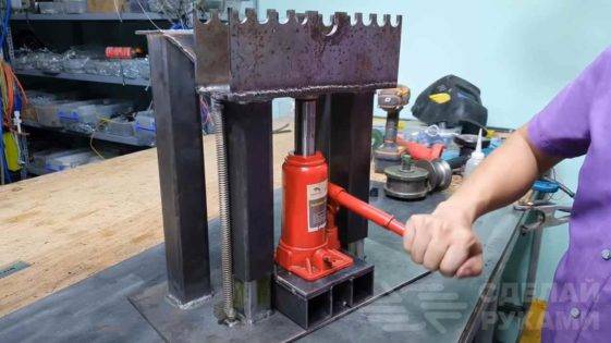
An automobile hydraulic jack is also additionally used, since the strength of the hands to bend the workpiece is definitely not enough. And with a jack, the device becomes truly functional.
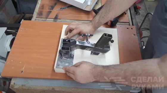
It is possible to make a machine out of wood with your own hands (or rather, only a frame for it) for processing / cutting metal only in a number of cases.
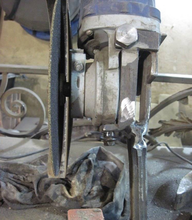
For example, this can be implemented when assembling a cutting machine based on a small grinder. In this case, the base is made of chipboard (you can take plywood).
But anyway, if you are making a metal cutting machine, then it is better to make the base for it more reliable and durable. It is not worth saving on material here - savings can go sideways.
You can weld a simple frame from a profile pipe with reinforcement in the central part, and then weld or bolt a metal sheet of a suitable size on top.
A bending machine for bending metal bars and strips also needs a very strong base.

If instead of a sheet of metal there was a plywood board, then the machine would simply not be able to cope with its task.
Therefore, to make wood machines your own hands for processing metal is possible only in cases where the load on the base (frame) will be insignificant.For example, a drilling stand or a cutting machine.
Design and dimensional drawings
Design begins with determining the types of work and the dimensions of the workpieces to be processed. Based on this, we outline the overall dimensions, the power of the drive motor, the length of the bed. It is not necessary to draw all the details in accordance with GOST. Enough technical drawing of all the details.
Calculate drilling points, determine the dimensions of mating parts. Separately, it is necessary to develop a kinematic diagram and an electrical circuit. In the kinematic scheme, we determine the center-to-center distances of gears or gearbox pulleys. The electrical diagram will make it possible to correctly connect electrical equipment.
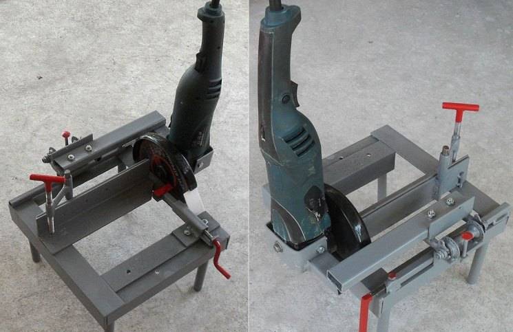
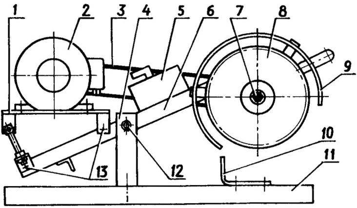
And what, in fact, are we talking about?
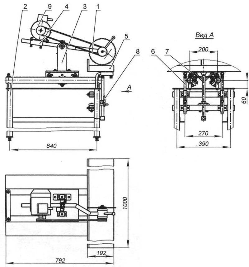
Only dozens of traditional designs of units for precise cutting of sheet, roll and long materials are known, this is not counting laser, etc. from the age of high technology. We will further consider machines with a swinging working module and a round rotating cutting body - an abrasive or saw blade. Such cutting machines are called pendulum. They are the most versatile (including suitable for broach - maintaining a longitudinal cut of limited length) and can be done independently in a shed-garage workshop. When they say “cutting machine”, in the vast majority of cases it is precisely the pendulum (pendulum cut grinder in English) that is meant.
Motor or angle grinder?
This refers to the drive of the machine - separate or combined in a monoblock with a working (cutting) body and a power transmission to it.A separate motor has the advantage that the swinging part of the unit - the rocking chair (pendulum, rocker) can be made properly balanced, which greatly simplifies the work on the machine and increases its productivity; the latter is relatively weakly dependent on the resistance of the material to cutting
In addition, the whole machine can be made suitable for intensive round-shift work, which can be important for those who derive income with hands growing from where they should and a head that works as they should. Angle grinder (Bulgarian), as you know, can work continuously for 20-60 minutes
(depending on the model), and then - a forced downtime for the tool to cool down. But for occasional use, angle grinders have a number of advantages:
- A sufficiently hardy and accurate cutting machine from a grinder can be made without turned parts and with a minimum of welding work or without them at all, see below.
- The basic tool remains suitable for manual work outside the machine.
- Power supply - single-phase 220 V from a household outlet.
- Starting devices and protective earthing are not required, because only angle grinders with double insulation are commercially available.
- The external characteristic of the collector electric motor of the angle grinder is softer than that of the asynchronous electric motor with a squirrel-cage rotor, which saves motor power and electricity consumption. In most cases (except for cutting thick, durable and / or viscous materials), it can be assumed that an 800 W electric grinder is equivalent to an asynchronous motor with 1.2 kW on the shaft (see below), and a 1300 W angle grinder is a separate motor for 2, 2 kW.
- Cutting machines from angle grinders are lighter, more compact and transportable than with a separate drive.
- Inexpensive angle grinders are not supplied with speed controllers, but a regular speed controller for a drill is suitable for them (no more than $20; usually $5 - $6). "Frequency" for an asynchronous motor up to 2.5 kW costs from $50.
About speed control
And why regulate the speed of the disk? In order not to exceed the maximum linear edge speed and/or rotational speed indicated on it. Otherwise, the disk may not break, but its performance will drop dramatically, wear will increase, and the quality of the cut will deteriorate. Rated speeds of rotation of asynchronous motors 2800-2850 min–1 allow the use of conventional discs with a diameter of up to 350-400 mm or more, which gives a cutting depth of at least 150 mm. The spindle of the grinder spins much faster (from 6000 min-1), and it is dangerous to put a regular disk with a diameter of more than 160 mm on it. The cutting depth is up to 50-60 mm, and a high-speed disc is expensive and wears out quickly. Installing a speed controller solves the problem. Productivity and cut quality do not suffer, because. determined by the linear speed of rotation along the cutting edge.
About the name
LBM sounds "technically", but in fact it is inaccurate, because. a grinder cuts a lot more than it grinds. "Angle drill" is even more unfortunate, because. to drill - to drill, drill, for which angle grinders are generally unsuitable. Angle grinder is tracing paper from English. angle grinder machine. But the English to grind is much broader in meaning than all types of abrasive processing. For example, a meat grinder is a meat grinder. “To grind” has no exact Russian analogue; in terms of meaning, this is something like "shred to shreds along the back streets." In general, the colloquial "Bulgarian" is terminologically incorrect, but short enough, and it is clear what it is.
And what, in fact, are we talking about?
Only dozens of traditional designs of units for precise cutting of sheet, roll and long materials are known, this is not counting laser, etc. from the age of high technology. We will further consider machines with a swinging working module and a round rotating cutting body - an abrasive or saw blade. Such cutting machines are called pendulum. They are the most versatile (including suitable for broach - maintaining a longitudinal cut of limited length) and can be done independently in a shed-garage workshop. When they say “cutting machine”, in the vast majority of cases it is precisely the pendulum (pendulum cut grinder in English) that is meant.


Motor or angle grinder?
This refers to the drive of the machine - separate or combined in a monoblock with a working (cutting) body and a power transmission to it. A separate motor has the advantage that the swinging part of the unit - the rocking chair (pendulum, rocker) can be made properly balanced, which greatly simplifies the work on the machine and increases its productivity; the latter is relatively weakly dependent on the resistance of the material to cutting
In addition, the whole machine can be made suitable for intensive round-shift work, which can be important for those who derive income with hands growing from where they should and a head that works as they should. Angle grinder (Bulgarian), as you know, can work continuously for 20-60 minutes
(depending on the model), and then - a forced downtime for the tool to cool down. But for occasional use, angle grinders have a number of advantages:
- A sufficiently hardy and accurate cutting machine from a grinder can be made without turned parts and with a minimum of welding work or without them at all, see below.
- The basic tool remains suitable for manual work outside the machine.
- Power supply - single-phase 220 V from a household outlet.
- Starting devices and protective earthing are not required, because only angle grinders with double insulation are commercially available.
- The external characteristic of the collector electric motor of the angle grinder is softer than that of the asynchronous electric motor with a squirrel-cage rotor, which saves motor power and electricity consumption. In most cases (except for cutting thick, durable and / or viscous materials), it can be assumed that an 800 W electric grinder is equivalent to an asynchronous motor with 1.2 kW on the shaft (see below), and a 1300 W angle grinder is a separate motor for 2, 2 kW.
- Cutting machines from angle grinders are lighter, more compact and transportable than with a separate drive.
- Inexpensive angle grinders are not supplied with speed controllers, but a regular speed controller for a drill is suitable for them (no more than $20; usually $5 - $6). "Frequency" for an asynchronous motor up to 2.5 kW costs from $50.
In general, if you assemble metal structures on site and have a vehicle, or trade in rolled metal (or long wood) cut to size from the customer, then you need to make a machine with a separate drive. If trimming and cutting exactly at an angle is not an everyday necessity for you, then a cutting bed for a grinder will be the best.
About speed control
And why regulate the speed of the disk? In order not to exceed the maximum linear edge speed and/or rotational speed indicated on it. Otherwise, the disk may not break, but its performance will drop dramatically, wear will increase, and the quality of the cut will deteriorate.Rated speeds of rotation of asynchronous motors 2800-2850 min–1 allow the use of conventional discs with a diameter of up to 350-400 mm or more, which gives a cutting depth of at least 150 mm. The spindle of the grinder spins much faster (from 6000 min-1), and it is dangerous to put a regular disk with a diameter of more than 160 mm on it. The cutting depth is up to 50-60 mm, and a high-speed disc is expensive and wears out quickly. Installing a speed controller solves the problem. Productivity and cut quality do not suffer, because. determined by the linear speed of rotation along the cutting edge.
About the name
LBM sounds "technically", but in fact it is inaccurate, because. a grinder cuts a lot more than it grinds. "Angle drill" is even more unfortunate, because. to drill - to drill, drill, for which angle grinders are generally unsuitable. Angle grinder is tracing paper from English. angle grinder machine. But the English to grind is much broader in meaning than all types of abrasive processing. For example, a meat grinder is a meat grinder. “To grind” has no exact Russian analogue; in terms of meaning, this is something like "shred to shreds along the back streets." In general, the colloquial "Bulgarian" is terminologically incorrect, but short enough, and it is clear what it is.
Conclusion
If the home master has the education of a turner or at least similar skills, a lathe on the farm will be useful. It will help save on the purchase of some parts for mechanical devices, polishing or even painting. Curly wooden legs for stools or tables are also made on it. As it became clear from the article, it is not so difficult to make such a unit with your own hands. You just need to be attentive to the schemes and follow certain rules.
And finally, about how to choose a lathe - the video is short, but fascinating and instructive. Happy viewing!
Watch this video on YouTube
Previous RepairHow to properly apply a sealant for plastic windows: general information and practical recommendations
Next RepairHow to switch windows to winter mode: professional advice to home masters


