- Protrusion Height
- Press welding (edge welding)
- Table 2. Parameters of welding angle DVS 2207 (ambient t 20ºС)
- Flange connection methods
- Types of welded joints and seams in gas welding
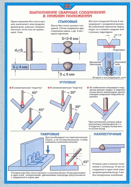
- The position of the rod when making various types of seams
- Insulating flange connections
- Insulating flange connections
- Available provisions
- lower
- Horizontal
- vertical
- Ceiling
- Flange pressure classes
- Welding consumables
- Gases used in work
- inert substances
- Active elements
- Common gas mixtures
- The essence of the MIG / MAG welding process
- gas valve
Protrusion Height
If you look at the drawing of a steel flange, then it has several parameters, including the height of the ledge. It is denoted by the letters H and B, it can be measured in all types of products, except for the one that has an overlap connection. The following should be remembered:
- pressure class 150 and 300 models will have a 1.6 mm protrusion height;
- pressure class 400, 600, 900, 1500 and 2000 models have a 6.4 mm protrusion height.
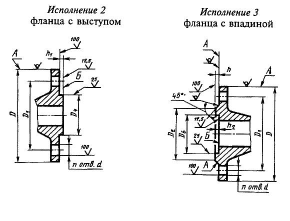
In the first case, suppliers and manufacturers of parts take into account the surface of the protrusion, in the second case, the surface of the protrusion is not included in the specified parameter. Parts brochures may list these in inches, where 1.6 mm is 1/16 inch and 6.4 mm - ¼ inch.
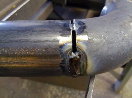
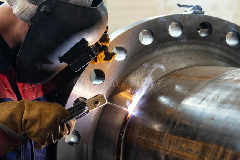
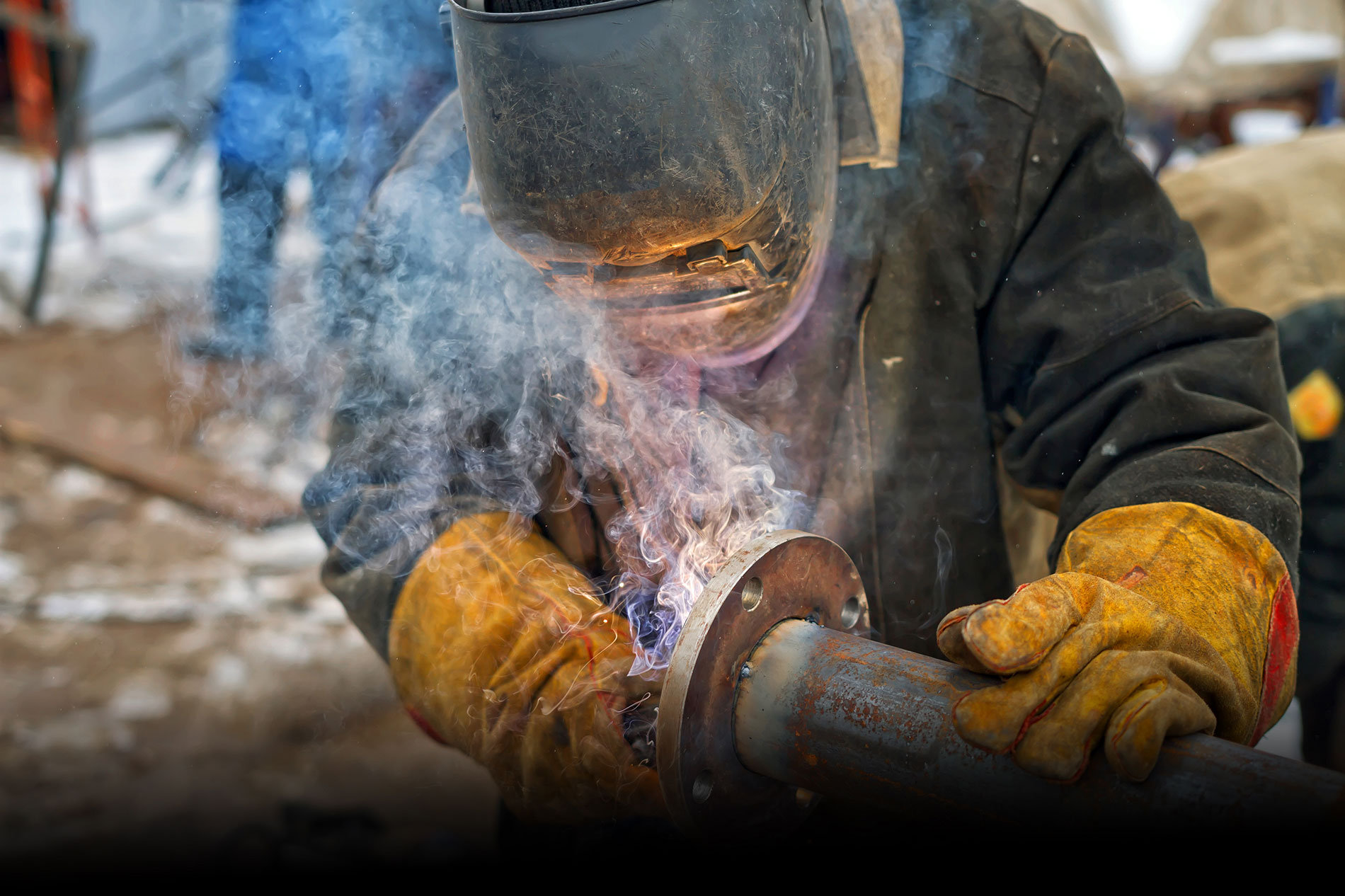
Press welding (edge welding)
PE pipes can be joined at the points of passage of the coupling by pressing welding inside and outside.
Although press welding is possible even for pipes without sleeves, this welding method is most often used in
wells and tanks in the production of fitting elbows, the production of pipes for special projects.
Press welding for connecting pipes to be used in high pressure lines,
but only for pipes and wells in lines with low pressure flows. There are two types of press welding machine,
which work in the same way.
- Hot air welding machine with electrodes.
- Hot air welding machine pressing granular raw materials.
Details to pay special attention to when joining PE pipes in edge welding:
- The ambient temperature must be at least 5ºС.
- Edge welding should not be used for gas and pressurized potable water lines.
- The material of the welding parts and the electrodes must be of the same grade, and the diameter of the electrodes must be 3mm or 4mm.
- The surfaces to be welded must be well cleaned, the oxidation from the surface must be scraped off, and then the surfaces can be welded.
- The welding process must always be carried out while maintaining a pressing angle of 45° with the surface.
- In bulk and deep welding of max. 4 mm thick welding must be applied immediately, observing the cooling process, then scrape everything off and weld again, this process is repeated until the desired thickness is reached.
Diagram 3. Preparation of parts for edge welding Diagram 4. Type of double-sided horizontal fillet welding Diagram 5. Type of one-sided vertical weldingType of one-sided horizontal welding
Table 2. Parameters of welding angle DVS 2207 (ambient t 20ºС)
| Welding material class | Welding force (N) | Air heating value for welding press (ºС) | Hot air flow rate (1/mm) | |
| 3 mm electrode | 4 mm electrode | |||
| HPDE | 10….16 | 25….35 | 300….350 | 40….60 |
| PP | 10….16 | 25….35 | 280….330 | 40….60 |
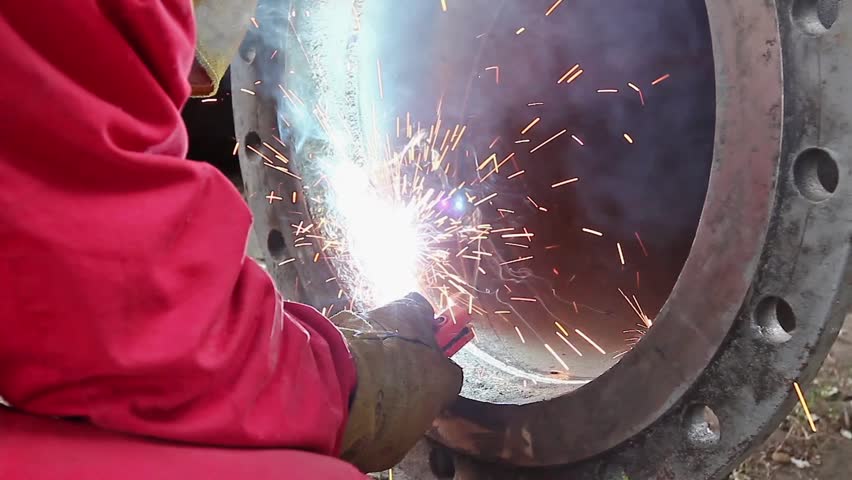
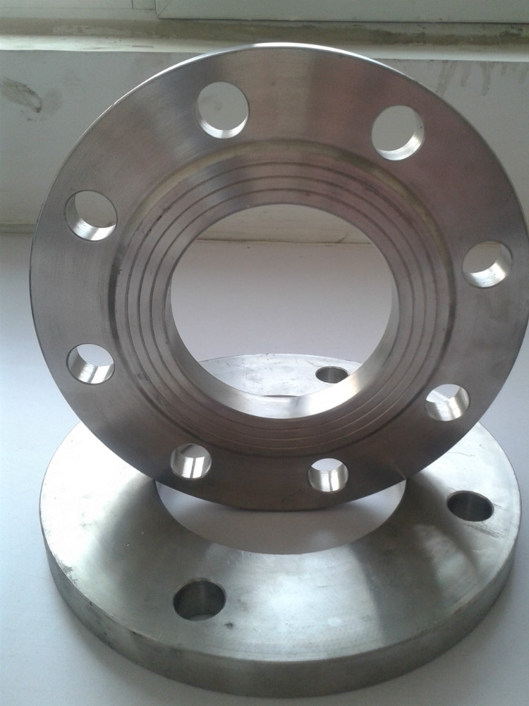
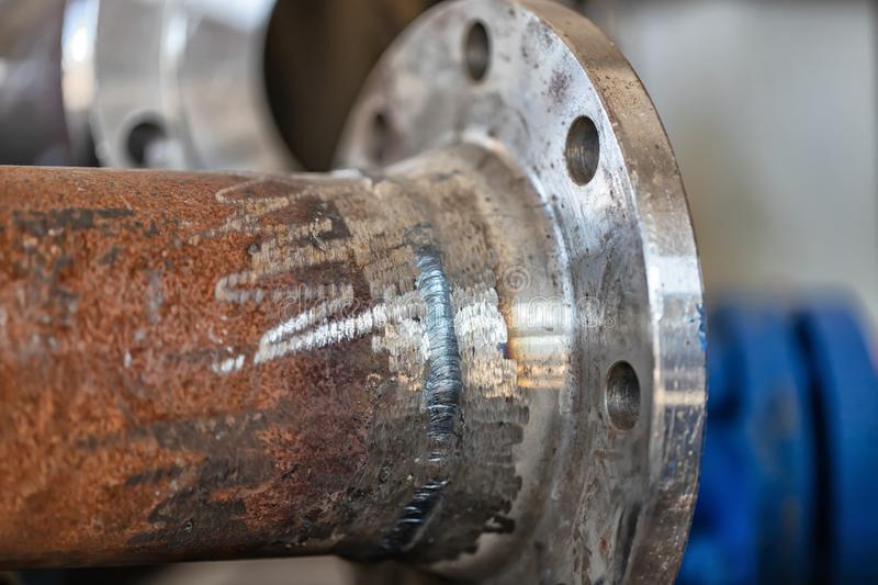
Flange connection methods
The flange connection method is used when it is necessary to connect PE pipes with such elements as a steel pipe, valve, pump, condenser
or if the pipeline needs to be dismantled in a certain part for a certain time.
After a steel ring, called a flange, is fixed on the PE pipe, the pipe will have an edge to support this flange,
called a flange adapter, which is welded to the edge of the pipe by butt welding. The two lines of pipes to be connected are placed
opposite each other, and then a gasket is placed between their edges, the connection of the flanges is carried out using bolts and nuts
Attention must be paid to the fact that the bolts must be tightened not in a circle, but in opposite rows.
It is especially important not to push the pipe while tightening the bolts to prevent overload.
Diagram 7
Flanged connection method
| The pipes are connected with an adapter after a vertical cut along the axis, and the fai is cut with a cone at an angle of about 15º and the pipe is screwed in in connection to the point of elevation. Then both pipes are placed and the bolts are manually tightened, which is how the connection is achieved. If the pipe diameter 40 mm and above, it is better to screw in the bolts with a special screwdriver than by hand. Adapters withstand pressure up to 20 atmospheres, but are not recommended for pipes with a diameter exceeding 110 mm. Diagram 8.Connection method using a connecting adapter |
Types of welded joints and seams in gas welding
In gas welding, butt, lap, tee, corner and end joints are used.
Butt joints (Fig. 1, a - d) are the most common due to the lowest residual stresses and deformations during welding, the highest strength under static and dynamic loads, as well as accessibility for inspection. A smaller amount of the base and filler metals is spent on the formation of the butt joint. The connection of this type can be made with a flare, without a bevel of the edges, with a bevel of one or two edges (V-shaped) or with two bevels of two edges (X-shaped).
The edges are blunted to prevent metal leakage when welding from the back of the seam. The gap between the edges facilitates penetration of the root of the seam. To obtain high quality joints, it is necessary to ensure the same gap width along the entire length of the seam, i.e. parallelism of the edges.

Rice. 1. Types of welded joints: a - butt without cutting edges and without a gap; b - butt without cutting edges and with a gap; c, d - butt with one- and two-sided beveled edges, respectively; d - overlap; f, g - tee without a gap and with a gap, respectively; h - end; and - angular
Details of small thickness can be butt-welded without cutting edges, medium thickness - butt-welded with one-sided bevel edges, large thickness - butt-welded with double-sided beveled edges. A double-sided bevel has advantages over a one-sided one, since with the same thickness of the welded metal, the volume of deposited metal with a double-sided bevel is almost 2 times less than with a one-sided one.At the same time, welding with a double-sided bevel is characterized by less distortion and residual stresses.
Lap joints (Fig. 1, e) are used in gas welding of thin metals, scarves, linings, pipe couplings, etc. When welding thick metals, this type of joint is not recommended, since it causes warping of products and can lead to the formation of cracks in them.
Lap joints do not require special edge processing (other than trimming). In such joints, it is recommended, if possible, to weld sheets on both sides. The assembly of the product and the preparation of sheets for overlap welding are simplified, however, the consumption of the base and filler metals is greater than butt welding. Lap joints are less durable under variable and shock loads than butt joints.
Tee joints (Fig. 1, f, g) are of limited use, since their implementation requires intense heating of the metal. In addition, such a connection causes warping of products. Tee joints are used when welding products of small thickness, they are made without beveled edges and are welded with fillet welds.
End connections (Fig. 1, h) are used when welding parts of small thickness, in the manufacture and connection of pipelines.

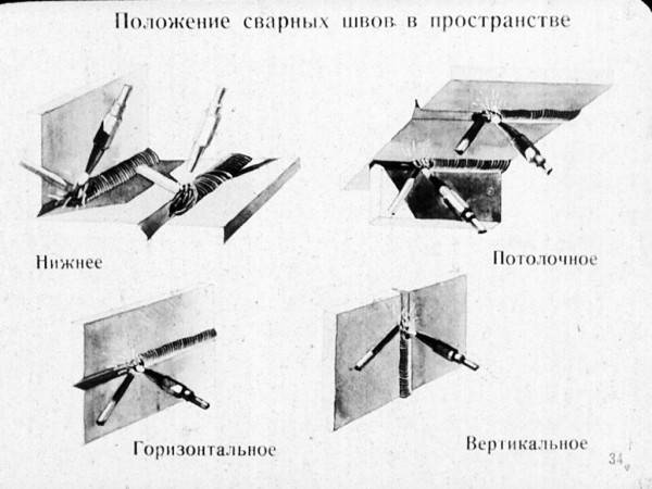
Rice. 2. Types of welds depending on the position in space: a - lower; b - vertical; c - horizontal; g - ceiling; arrows show welding direction

Rice. Fig. 3. Types of welds depending on the acting force F: a - flank; b - frontal; c - combined; g - oblique
Corner joints (Fig.1, i) are used when welding tanks, flanges of pipelines for non-critical purposes. When welding metals of small thickness, it is possible to make fillet joints with flare and not to use filler metal.


Depending on the types of welded joints, butt and fillet welds are distinguished.
According to the position in space during the welding process, the seams are divided into lower, vertical, horizontal, ceiling (Fig. 2). The best conditions for formation weld and joint formation are created when welding in the lower position, therefore welding in other positions in space should be used only in exceptional cases.
According to the location relative to the acting force, there are flank (parallel to the direction of the force), frontal (perpendicular to the direction of the force), combined and oblique seams (Fig. 3).
Depending on the profile of the cross section and the degree of convexity, the seams are divided into normal, convex and concave (Fig. 4).
Under normal conditions, convex and normal seams are used, concave seams - mainly when performing tacking.

Rice. 4. The shape of the welds: a - normal; b - convex; c - concave
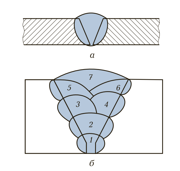
Rice. 5. Single layer (a) and multilayer (b) welds: 1 - 7 - sequence of layers

Rice. 6. Continuous (a) and intermittent (b) welds
According to the number of deposited layers, the welds are divided into single-layer and multi-layer (Fig. 5), according to the length - into continuous and intermittent (Fig. 6).
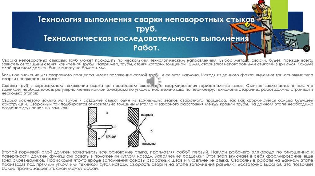
The position of the rod when making various types of seams
Connections are usually divided into docking, ceiling, corner, horizontal, overlapping, vertical, tee and others.The characteristics of the space between the parts determine the number of passes for which it will be possible to lay an even and high-quality seam. Small and short connections are made in one pass, long ones in several. You can suture continuously or pointwise.
The selected welding technique will determine the strength, resistance to stress and reliability of the junction of parts. But before choosing a scheme of work, it is necessary to determine the position of the rod. It is defined:
- spatial position of the junction;
- thickness of the welded metal;
- metal grade;
- consumable diameter;
- electrode coating characteristics.
The correct choice of the position of the rod determines the strength and external data of the joint, and the technique for welding seams in various positions will be as follows:
- "From oneself", or "forward corner". The rod during operation is inclined by 30-600. The tool is moving forward. This technology is used when connecting vertical, ceiling and horizontal joints. This technique is also used for welding pipes - it is convenient to connect fixed joints with electric welding.
- Right angle. The method is suitable for welding hard-to-reach joints, although it is considered universal (you can weld places with any spatial arrangement). The position of the rod under 900 complicates the process.
- "On yourself", or "back corner". The rod during operation is inclined by 30-600. The tool advances towards the operator. This electrode welding technique is suitable for corner, short, butt joints.
Properly chosen position of the tool guarantees the convenience of sealing the joint, and allows you to monitor the correct penetration of the material.The latter fact ensures high-quality formation and strength of the working connection. The correct technique for welding with an inverter is the penetration of materials to a shallow depth, the absence of spatter, the uniform capture of the edges of the joint, the uniform distribution of the melt. How the connecting weld should turn out can be seen in a video for beginner welders.
Insulating flange connections
Thus, it simultaneously does not absorb moisture and avoids the passage of electric current through the pipeline. Sometimes gaskets are also made from PTFE or vinyl plastic. The IFS also contains tightening studs, polyamide bushings, washers and nuts. Thanks to these hardware, the flanges are pulled together and fixed in this position. Order the manufacture of flanges only from us.
In general, insulating flange connections are a strong connection between two pipeline elements. An important role in it is played by an electrically insulating gasket, which makes it possible to exclude the ingress of electric current into the pipeline. On average, the resistance of one insulating flange connection is at least 1000 ohms.
Insulating flange connections
IFS is a composite structure produced in the conditions of the enterprise, which has the necessary tightness and isolation. Its main function is to cathodically protect underground and above-ground pipes and thus extend their service life.
Installation process
- The installation of the IFS is carried out at the place where the pipes come out of the ground and at the entrance to it. The need for its installation is due to the likelihood of the pipe coming into contact with electrical contacts, grounding and other communications. Including at the outlets of pipelines of GDS, GRU, GRP.
- The installation of the IFS is immediately included in the project during its preparation and is carried out by special installation teams.
Our company is ready to produce these designs of any diameter specified by the customer. Production is carried out on the basis of GOST. For example, we offer products from high-carbon brand 09g2s with steel hardware 40x., Fluoroplastic bushings.
We keep all guests
Insulating connections
Insulating flanges are not recommended for installation on those gas pipelines that are located in explosive areas. Including gas distribution stations, in places where gas is cleaned and odorized.
IFS are designed to block the ingress of stray electric current into the pipeline. To do this, the flange connection, assembled at the enterprise, is equipped with insulating gaskets made of dielectrics (textolite, paronite, klinergit, etc.). Insulating materials are placed not only between the flanges, hardware is also made from special materials:


In other words, FSIs are used to create electrical sectioning of parts that are located underground and above it. The safety of the gas pipeline depends on the form in which the flanges will be contained.
In the manufacture of insulating flange connections and installation in hazardous places (with compressor stations, tanks, etc.), where the magnitude of the current in the pipelines can be high, it is necessary to regularly check and prevent the working condition of the IFS. For this, the insulating flanges must be located in specially created working wells.
Such structures must necessarily be equipped with control conductors that go outside. This is necessary so that service workers can carry out the necessary electrical measurements without descending into the well.
IFS are not only used as protective structures on pipelines from the corrosive effects of electric current, they are also installed when gas and oil products approach pumping stations and other structures.
Available provisions
Spatial positions during welding have four options. The most easily performed of these is the horizontal lower position. The most difficult is also the horizontal position of the seam, but located at the top, and having the name of the shelf. The seam in the horizontal direction is not necessarily performed at the bottom or at the top. It can be located in the center of a vertical wall. The remaining option belongs to the vertical position.
Different welding positions in space have their own nuances when welding. The location of the electrodes depends on the type of positions.
lower
This position is the most desirable for any welder. This option is used when simple small-sized parts are welded or if strict requirements are not imposed on the quality of the seam. The position of the electrode in this view is vertical. In this position, welding is possible, both on one side and on both sides.
The quality of the seam in the lower position is influenced by the thickness of the parts to be welded, the size of the gap between them, and the magnitude of the current. This method has high performance. The disadvantage is the occurrence of burns. In the lower position, you can use the methods of butt and corner joints.
Horizontal
In this form, the connected elements are in a vertical plane. The weld is horizontal. The electrode belongs to the horizontal plane, but is located perpendicular to the seam. Difficulty in operation causes a possible splashing of liquid metal from the weld pool and falling under the action of its own weight directly onto the edge located below. Before starting work, it is necessary to carry out preparatory work, namely, trimming the edges.
vertical
The parts to be welded are placed in a vertical plane so that the seam between them is also vertical. The electrode is located in a horizontal plane perpendicular to the seam.
The problem of drops of hot metal falling down remains. Work should be performed exclusively on a short arc. This will prevent liquid metal from entering the weld crater. It is recommended to use coated electrodes that increase the viscosity of the contents of the weld pit. This will significantly reduce the downward flow of molten metal.
Of the two existing methods of movement, if possible, movement from the bottom to the top should be chosen. Then, inevitably, the flowing metal will form a step during solidification, preventing its further sliding. It takes a long time. When using the top-down method, productivity is increased at the cost of reduced weld quality.
Ceiling
In fact, it is a horizontal seam located in an inconvenient place for work. The welder has to stay in a difficult position with his arm outstretched for a long time. Of course, this does not depend on qualifications, but experienced craftsmen have their own techniques that facilitate the welding process in this position. In any case, you need to periodically take breaks.
The position when welding parts will be horizontal, and the electrode - vertical. The seam is located at the bottom of the edges. The main risk of obtaining a poor-quality weld is that the liquid metal flows down, but does not always enter the weld pool.
When welding overhead, a small current and a minimally short arc should be used. The electrodes must have a small diameter and a refractory coating that holds metal drops due to surface tension. This type of welding is especially undesirable when parts of small thickness are to be joined.
Flange pressure classes
Parts manufactured according to Asme (Asni) standards are always characterized by a number of parameters. One of these parameters is the nominal pressure. In this case, the diameter of the product must correspond to its pressure according to the established samples. The nominal diameter is indicated by a combination of the letters "DU" or "DN", followed by a number characterizing the diameter itself. Nominal pressure is measured in "RU" or "PN".
The pressure classes of the American system correspond to the conversion to MPa:
- 150 psi - 1.03 MPa;
- 300 psi - 2.07 MPa;
- 400 psi - 2.76 MPa;
- 600 psi - 4.14 MPa;
- 900 psi - 6.21 MPa;
- 1500 psi - 10.34 MPa;
- 2000 psi - 13.79 MPa;
- 3000 psi - 20.68 MPa.
Translated from MPa, each class will indicate the flange pressure in kgf / cm². The pressure class determines where the selected part will be used.
Welding consumables
The assembly of main pipelines is carried out using manual, semi-automatic and automatic electric welding.
For these purposes, the following materials are used:
- electrodes of various brands,
- fluxes and
- welding wire.
Consider the requirements for their quality.
For automatic gas-electric welding of pipe joints, the following are used:
- welding wire with a copper-plated surface according to GOST 2246-79;
- carbon dioxide according to GOST 8050-85 (gaseous carbon dioxide);
- gaseous argon according to GOST 1057-79;
- mixture of carbon dioxide and argon.
For automatic submerged arc welding of pipe joints, fluxes are used in accordance with GOST 9087-81 and carbon or alloyed wire with a predominantly copper-plated surface in accordance with GOST 2246-70. The grades of fluxes and wires are selected in accordance with the technological instructions, depending on the purpose and standard rupture resistance of the metal of the pipes being welded.


For mechanized welding of pipe joints, or welding of pipes, flux-cored wires are used, the grades of which are selected in accordance with technological instructions.
For manual arc welding of pipeline joints or a flange and a pipe section, electrodes with cellulose (C) and basic (B) types of coatings are used according to GOST 9466-75 and GOST 9467-75.
Table 6.4 provides recommendations for choosing the type of electrodes.
For gas cutting of pipes are used: according to
- technical oxygen according to GOST 5583-78;
- acetylene in cylinders according to GOST 5457-75;
- propane-butane mixture according to GOST 20448-90.
Table 1. Types of electrodes used in welding pipelines (flange and pipe).
| Standard value (according to TU) temporary resistance rupture of pipe metal, 102 MPa (kgf/mm2) | Purpose electrode | Electrode type (according to GOST 9467-75) — type of electrode coatings (according to GOST 9466-75) |
| Up to 5.5 (55) | For welding the first (root) layer of the seam fixed joints pipes | E42-C |
| Up to 6.0 (60) incl. | E42-C, E50-C | |
| Up to 5.5 (55) | For hot welding fixed passage pipe joints | E42-C, E50-C |
| Up to 6.0 (60) incl. | E42-C, E50-C E60-C | |
| Up to 5.0 (50) incl. | For welding and repair root layer welding seam rotary and fixed pipe joints | E42A-B, E46A-B |
| Up to 6.0 (60) incl. | E50A-B, E60-B | |
| Up to 5.0 (50) incl. | For lining from the inside pipes | E42A-B, E46A-B |
| Up to 6.0 (60) incl. | E50A-B | |
| Up to 5.0 (50) incl. | For welding and repair filling and facing layers of the seam (after "hot" pass electrodes C or after root layer of the seam, performed by electrodes B) | E42A-B, E46A-B |
| From 5.0 (50) Up to 6.0 (60) incl. for welding | E50A-B, E55-C | |
| From 5.5 (55) up to 6.0 (60) incl. | E60-B, E60-C, E70-B |
Gases used in work
In industry, mixtures of several elements are more often used. The following substances can be used separately: hydrogen, nitrogen, helium, argon. The choice depends on the metal alloy and on the desired characteristics of the future seam.


inert substances
These impurities give stability to the arc and allow deep soldering. They protect the metal from the effects of the environment, while not having a metallurgical effect. It is advisable to use them for alloy steel, aluminum alloys.

Inert substances allow for deep soldering.
Active elements
The peculiarity of welding is that the joints react with the workpiece and change the properties of the metal. Depending on the type of metal sheet, gas substances and their proportions are selected. For example, nitrogen is active towards aluminum and inert towards copper.
Common gas mixtures
Active substances are mixed with inert ones in order to increase the stability of the arc, increase work productivity, and change the shape of the seam. With this method, part of the electrode metal passes into the melting region.
The following combinations are considered the most popular:
- Argon and 1-5% oxygen. Used for alloy and low carbon steel. At the same time, the critical current decreases, the appearance improves, and the appearance of pores is prevented.
- Carbon dioxide and 20% O2. It is applied to carbon steel sheet when working with a consumable electrode. The high oxidation ability of the mixture gives deep penetration and clear boundaries.
- Argon and 10-25% CO2. Used for meltable items. This combination increases the stability of the arc and reliably protects the process from drafts. The addition of CO2 when welding carbon steel achieves a uniform structure without pores. When working with thin sheets, seam formation is improved.
- Argon with CO2 (up to 20%) and O2 (up to 5%). It is used for alloyed and carbon steel structures. Active gases help to make the place of melting neat.
Argon and oxygen are the most popular combination of gases for welding.
The essence of the MIG / MAG welding process
Mechanized gas-shielded consumable arc welding is a type of electric arc welding in which the electrode wire is automatically fed at a constant speed, and the welding torch is manually moved along the seam. In this case, the arc, the stick-out of the electrode wire, the pool of molten metal and its solidifying part are protected from the effects of ambient air by a shielding gas supplied to the welding zone.
The main components of this welding process are:
- a power source that provides the arc with electrical energy;
- a feeder that feeds an electrode wire into the arc at a constant speed, which melts with the heat of the arc;
— shielding gas.
The arc burns between the workpiece and the consumable electrode wire, which is continuously fed into the arc and which serves as filler metal. The arc melts the edges of the parts and the wire, the metal of which passes to the product into the resulting weld pool, where the metal of the electrode wire is mixed with the metal of the product (that is, the base metal). As the arc moves, the molten (liquid) metal of the weld pool solidifies (that is, crystallizes), forming a weld that connects the edges of the parts. Welding is performed with direct current of reverse polarity, when the positive terminal of the power source is connected to the burner, and the negative terminal is connected to the product. Sometimes direct polarity of the welding current is also used.
Welding rectifiers are used as a power source, which must have a rigid or gently dipping external current-voltage characteristic. This characteristic provides automatic restoration of the set arc length in case of its violation, for example, due to the fluctuations of the welder's hand (this is the so-called self-regulation of the arc length). For more details on power sources for MIG/MAG welding, see Power sources for arc welding.
As a consumable electrode, an electrode wire of a solid section and a tubular section can be used. A tubular wire is filled inside with a powder of alloying, slag and gas-forming substances. Such a wire is called flux-cored wire, and the welding process in which it is used is flux-cored wire welding.
There is a fairly wide selection of welding electrode wires for welding in shielding gases, differing in chemical composition and diameter. The choice of the chemical composition of the electrode wire depends on the material of the product and, to some extent, on the type of shielding gas used. The chemical composition of the electrode wire should be close to the chemical composition of the base metal. The diameter of the electrode wire depends on the thickness of the base metal, the type of weld and the position of the weld.
The main purpose of the shielding gas is to prevent direct contact of the ambient air with the metal of the weld pool, stick out of the electrode and the arc. Shielding gas affects the stability of the arc, the shape of the weld, the depth of penetration and the strength characteristics of the weld metal. For more information about shielded gases, as well as welding wires, see the article Introduction to gas shielded arc welding (TIG, MIG/MAG).
gas valve
The gas valve is used to conserve shielding gas. It is advisable to install the valve as close as possible to the welding torch. At present, the most widespread solenoid gas valves. In semi-automatic devices, gas valves built into the handle of the holder are used. The gas valve must be turned on in such a way that a preliminary or simultaneous with the ignition of the arc supply of protective gas, as well as its supply after the arc breaks, until the weld crater is completely solidified, are ensured. It is desirable to be able to also turn on the gas supply without starting welding, which is necessary when setting up the welding installation.
Gas mixers are designed to produce gas mixtures when it is not possible to use a pre-prepared mixture of the desired composition.


