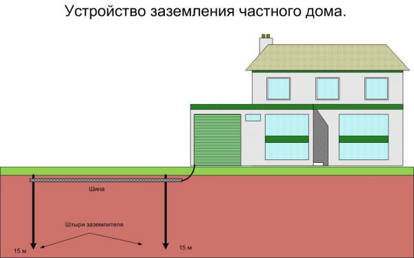
- Types of grounding
- I 4
- Overview of Methods
- Ammeter-voltmeter method
- Use of special devices
- Working with current clamps
- Types of grounding systems
- Test Method
- A megohmmeter is best used to assess other safety factors
- Current clamp
- Ground types
- We fill out the act (grounding test protocol)
- Application of ammeter and voltmeter
- Why measure contact resistance (PS)
- How to check the quality of grounding
- What is the frequency of measurements?
- Checking the presence and correct connection of protective earth
- What is the frequency of measurements?
- How to measure correctly
- Basic concepts
- Results and conclusions
Types of grounding
In electrical engineering, the concept of grounding is divided into two types - natural and artificial.
- Natural grounding is represented by conductive structures that are permanently in the ground. These include water pipes and other types of communications. Such structures cannot be used for grounding electrical installations, since they have non-standardized resistance. In order to guarantee safe conditions, it is recommended to use a special potential equalization system. In accordance with this system, all metal structures are connected to a zero protective conductor.
- Artificial grounding is performed in the form of a deliberate electrical connection of any points of electrical installations, equipment or electrical networks with a grounding device. The grounding device includes a grounding conductor and a grounding conductor, with the help of which the grounded part and the grounding conductor are connected. The structures of such systems can be made both in the form of simple metal rods and in the form of complex complexes, including special elements and other components.
The quality of grounding depends entirely on the amount of resistance provided to the spreading of current through the grounding device. The smaller this value, the better the grounding quality. Resistance can be reduced by increasing the area of the ground electrodes and reducing the electrical resistivity of the soil. For this purpose, the number of electrodes or the depth of their occurrence increases.
Over time, under the influence of corrosion or due to changes in soil resistivity, the parameters of the grounding system can deviate significantly from the original value. That is why periodic checks during operation are required. Malfunctions may not manifest themselves for a long time, until a dangerous situation occurs.
I 4
,= 1
where Rxi - resistance obtained in the /-th dimension, Ohm; n is the number of measurements.
3.4.2. Static instability of contact resistance A RCT in ohms is calculated by the formula _
ARCT \u003d \H, X^cp-Rx,)2-
3.5. Measurement accuracy indicators
3.5.1. The measurement error of the static instability of the contact resistance is within + 10% with a probability of 0.95.
four.METHOD FOR MEASURING DYNAMIC INSTABILITY OF TRANSITION RESISTANCE OF CONTACT
4.1. Principle and mode of measurement
4.1.1. The principle of measurement is to determine the value of the maximum change in the voltage drop across the contact junction during tests in dynamic mode. The type of tests must correspond to that specified in the standards or specifications for products of specific types in accordance with GOST 20.57.406-81.
(Revised edition, Rev. No. 1).
4.1.2. The measurement is carried out at direct current; The EMF of the electrical circuit must be no more than 20 mV and the current no more than 50 mA or in the mode specified in the standards or specifications for products of specific types.
4.2. Equipment
4.2.1. The measurement is carried out on the installation, the electrical circuit of which is shown in Fig. 2.

G is the current source; SA1, SA2 - switches; RA - ammeter; R1 - variable resistor; Rk - calibration resistor; U - amplifier; R oscilloscope; XI, X2, X3, . . . , Хп - measured contacts: 1, 2, 3, 4, . . . , n are the positions of the measured contacts
Crap. 2
(Revised edition, Rev. No. 1).
4.2.2. The error of the ammeter is within ± 1%.
4.2.3. A device for measuring the dynamic instability of the contact resistance must have a rectilinear frequency response in the frequency range from 400 Hz to 1 MHz with an unevenness of + 3 dB and be sensitive at frequencies up to 1 MHz:
50 μV / cm - when measuring resistance up to 5 mOhm;
500 µV/cm - when measuring resistance over 5 to 30 mOhm;
1.0 mV / cm - when measuring resistance above 30 mOhm.
(Revised edition, Rev. No. 1).
4.2.4. (Deleted, Rev. No. 1).
4.2.5.The resistance of the calibration resistor must be equal to the contact resistance specified in the standards or specifications for specific types of products with a tolerance of + 1%.
4.2.6. The cable connecting the tested products to the installation should be no more than 10 m long and have a grounded shielding braid.
4.3. Preparing and taking measurements
4.3.1. Products are mounted on a device that creates a dynamic effect. Mounting method - according to standards or specifications for specific types of products.


(Revised edition, Rev. No. 1).
4.3.2. Before measuring the dynamic instability of the contact resistance, the oscilloscope is calibrated. The SA2 switch is set to position 1 and the dependence of the signal amplitude on the current value at three to five points is checked on the oscilloscope. The non-linearity of this dependence should be within + 10%.
4.3.3. (Deleted, Rev. No. 1).
4.3.4. The value of the effect of interference on the transition resistance of the contact is determined with the switch SA1 open and subtracted from the value of the total signal received by the oscilloscope when measuring the voltage drop across the contact transition during tests in dynamic mode.
(Revised edition, Rev. No. 1).
4.3.5. Switch SA2 is transferred from position 1 to positions 2, 3, 4, . . . , n (see Fig. 2), alternately measuring the voltage drop across the contact junction on the oscilloscope.
4.3.6. The measurement of the instability of the resistance of contacts is carried out for the time specified in the standards or specifications for products of specific types.
(Introduced additionally, Rev. No. 1).
4.4. Results processing
4.4.1. Dynamic instability DH as a percentage calculated by the formula
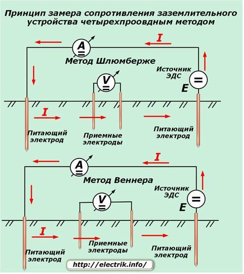
Overview of Methods
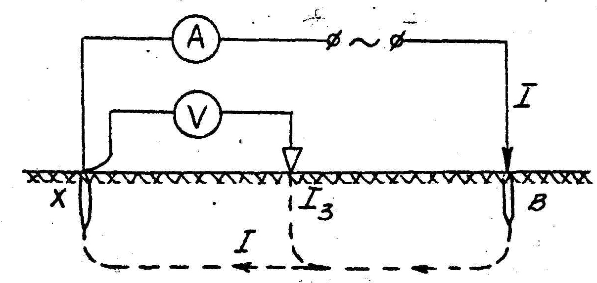
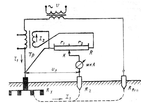
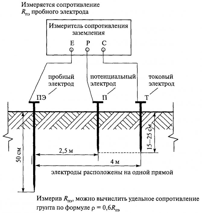
Ammeter-voltmeter method
To carry out measuring work, it is necessary to artificially assemble an electrical circuit in which the current flows through the tested ground electrode and the current electrode (it is also called auxiliary). Also in this circuit, a potential electrode is used, the purpose of which is to measure the voltage drop during the flow of electric current through the ground electrode. The potential electrode must be placed equally far from the current electrode and the tested ground electrode, in the zone with zero potential.
To measure resistance using the ammeter-voltmeter method, you must use Ohm's law. So, according to the formula R=U/I we find the resistance of the ground loop. This method is well suited for measurements in a private house. To obtain the desired measuring current, you can use a welding transformer. Other types of transformers are also suitable, the secondary winding of which is not electrically connected to the primary.
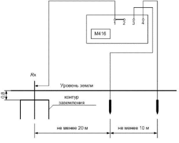
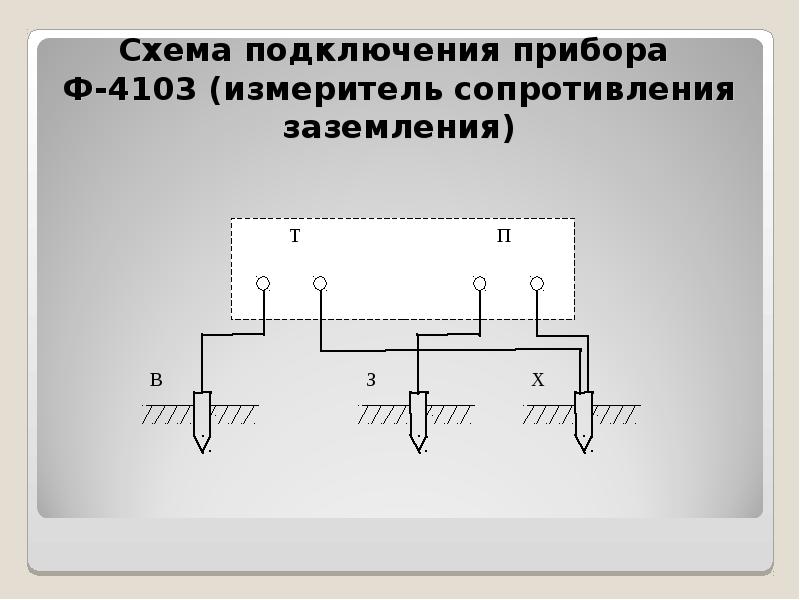
Use of special devices
We note right away that even for measurements at home, a multifunctional multimeter is not very suitable. To measure the resistance of the ground loop with your own hands, analog instruments are used:
- MS-08;
- M-416;
- ISZ-2016;
- F4103-M1.
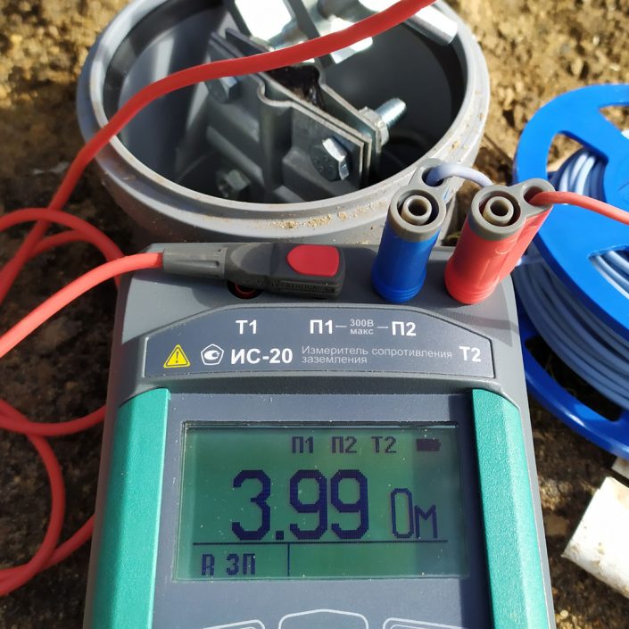
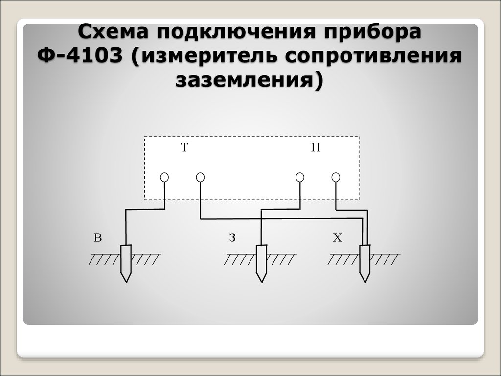
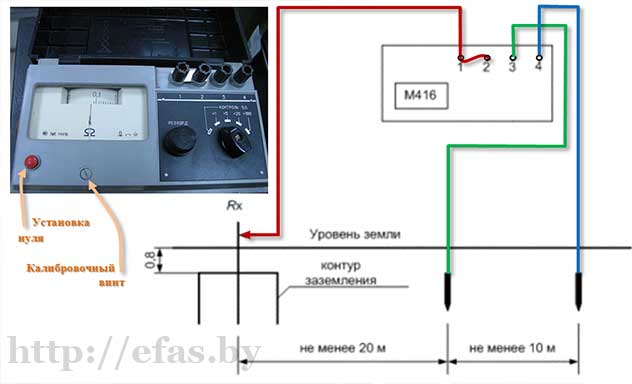
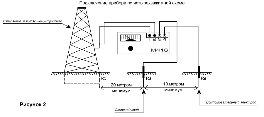
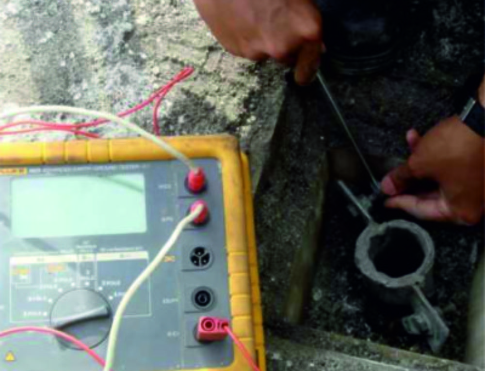
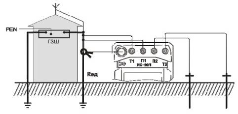
Let's consider how to measure the resistance with the M-416 device. First you need to make sure that the device has power. Let's check the batteries. If they are not there, you need to take 3 batteries with a voltage of 1.5 V. As a result, we get 4.5 V. The device, ready for use, must be placed on a flat horizontal surface. Next, we calibrate the device. We put it in the “control” position and, holding the red button, set the arrow to the “zero” value.For the measurement, we will use a three-clamp circuit. We drive the auxiliary electrode and the probe rod at least half a meter into the ground. We connect the wires of the device to them according to the scheme.
The switch on the device is set to one of the positions "X1". We hold the button and turn the knob until the arrow on the dial is equal to the “zero” mark. The result obtained must be multiplied by the previously selected multiplier. This will be the desired value.
The video clearly demonstrates how to measure ground resistance with a device:
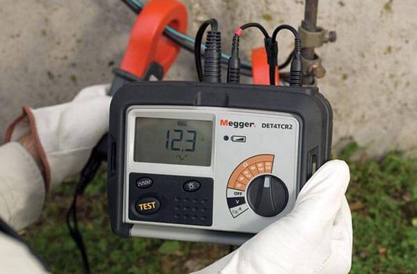
More modern digital instruments can also be used, which greatly simplify the work on measurements, are more accurate and save the latest measurement results. For example, these are devices of the MRU series - MRU200, MRU120, MRU105, etc.
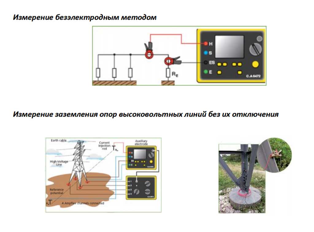
Working with current clamps
The ground loop resistance can also be measured with a current clamp. Their advantage is that there is no need to turn off the grounding device and use auxiliary electrodes. Thus, they allow you to quickly control the grounding. Consider the principle of operation of current clamps. An alternating current flows through the grounding conductor (which in this case is the secondary winding) under the influence of the primary winding of the transformer, which is located in the measuring head of the clamp. To calculate the resistance value, it is necessary to divide the EMF value of the secondary winding by the current value measured by the clamps.
At home, you can use current clamps C.A 6412, C.A 6415 and C.A 6410.You can learn more about how to use clamp meters in our article!
This is interesting: The light in the apartment is flashing - the reasons, what to do?
Types of grounding systems
The basis of all existing grounding systems used in electrical installations with voltages up to 1000 volts is the TN system with a solidly grounded neutral of the power source. It is connected to open conductive parts of electrical installations using zero protective conductors.
The TN-C system involves the combination of zero working and protective conductors in a single wire throughout its entire length. It has become widespread in old residential buildings because of its simplicity and economy. However, the TN-C system is not recommended for use in new buildings, since an emergency break in the PEN wire can lead to line voltage on connected electrical appliances. Due to the lack of a separate PE ground wire, safety is significantly reduced, so zeroing is used quite often. In this case, a short circuit causes the circuit breaker to trip.
A more modern and safer grounding scheme is the TN-S system with the separation of the zero working and protective conductors along their entire length. It is used in new buildings and successfully protects people and equipment. The TN-S system is more expensive, since five-core wires are required for laying a three-phase network, and three-core conductors for a single-phase network.
In the TN-C-S system, the protective and working neutral conductors in a certain area are combined in one wire. It is easy to install and widely used in various facilities.However, if the PEN conductor breaks before the separation point, line-to-line voltage may appear on the connected electrical appliances.


Test Method
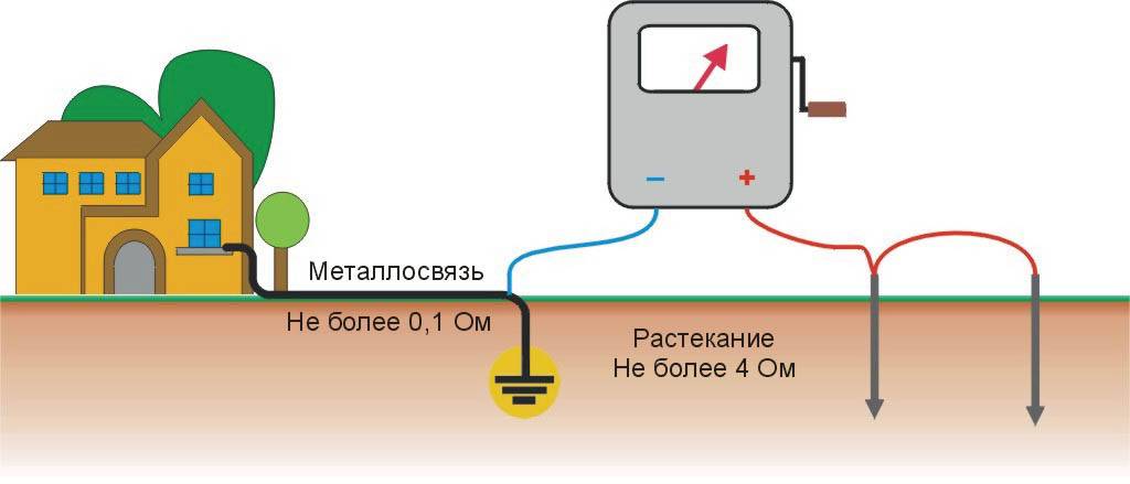
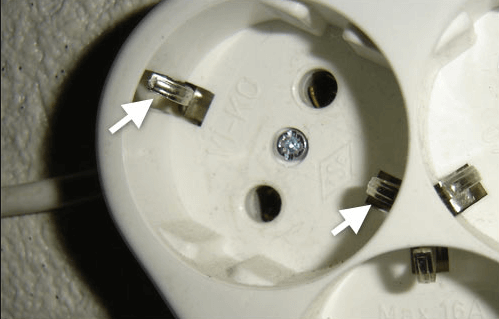
So to find out is there grounding in the house, first you need to turn off the electricity on the input shield and disassemble one of the sockets. After that, you should visually see if the yellow-green wire is connected to the corresponding terminal on the socket, as shown in the photo below:
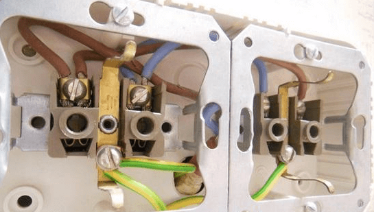
If only two cores are connected to the terminals, for example, with blue and brown insulation (zero and phase, according to the color marking of the wires), then you do not have grounding in the house or apartment. And one more thing - if there is a jumper between zero and the ground terminal, it means that the electrical wiring was grounded before you in the room, which is extremely dangerous.
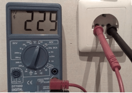
So, let's say all three conductors are in the screw terminals, and you want to check the grounding in the outlet. First, we recommend that you test the effectiveness of the ground loop with a multimeter. It is done very simply:
- Turn on the power at the panel.
- Switch the tester to voltage measurement mode.
- Measure the voltage between phase and zero.
- Perform a similar measurement between phase and ground.
If in the latter case the multimeter shows a voltage slightly different from the first measurement, then grounding is present in a private house or apartment. Did the numbers appear on the scoreboard? The ground loop is missing or not working. We talked about how to use a multimeter at home in the corresponding article!
If you don’t have a tester at hand, you can check the quality of the grounding using a test light assembled from improvised means.So, you can make a test lamp yourself according to the following scheme (1 - cartridge, 2 - wires, 3 - limit switches):

Using an indicator screwdriver, you need to check where the phase is and where is zero. Not always the connection of the outlet is made according to the rules. Perhaps someone who connected the contacts confused them with colors and now the phase is blue, which is not correct.
First, touch one end of the wire to the phase terminal, and the other to the zero. The control lamp should light up. After that, move the end of the wire with which you touched zero to the grounding antennae (shown in the photo below).
If the light is on - the circuit is working, dim light - the condition of the ground circuit is unsatisfactory. The light is not on, which means that the "ground" is not working. It should also be noted here that if the circuit is protected by a residual current device, when checking the reliability of the ground, the RCD may trip, which also indicates the operability of the ground loop.
If you touched the wires from the control to the phase and ground, but the light is off, try moving the limit switch to zero from the phase terminal to check the circuit. This is the case when there is a chance that the connection was wrong and the phase is not the right color.
A megohmmeter is best used to assess other safety factors
For example, insulation resistance. It's not about direct danger. That is, if you grab a wire in which the dielectric properties of the insulation are normal, you will not get an electric shock.
But there is an additional danger: insulation breakdown under load. This unpleasant fact leads to malfunctions, and what is more terrible - to fires in the electrical circuit.
The megohmmeter for measuring insulation resistance is a voltage generator and an accurate instrument in one housing.
The classic version (successfully used even now), generates voltage up to 2500 volts. Do not be afraid, the currents during operation are scanty. But you need to hold on only to the insulated handles of the measuring cables.
A high voltage potential easily reveals flaws in the insulation, and the needle of the device shows the true resistance. Before starting work, you should turn off all the power supply machines, and get rid of the residual potential: ground the wire.
To measure the breakdown between wires in one cable, two wires are used. They are connected to the cores of the disconnected cable, and a measurement is taken. If the resistance is below the norm, the cable is rejected. No one knows when a potential breakdown site will bring trouble.
To measure leakage to earth, one wire is connected to protective earth (in the zone of laying the cable under test), and the second to the central core. The test voltage must be higher. If the wire cannot be applied to the "ground", the measurement is carried out by applying a second electrode to the outer surface of the insulation.
In the presence of a screen (cable armor), a three-wire measurement system is used. the third wire is connected to the shield of the cable under test.
The general scheme is exactly the same, but each model of the device has its own instructions. In modern megohmmeters with a digital display, it is even easier to figure it out than in the old switch ones.
Using a megohmmeter, you can also test the motor windings. But this is a separate issue.Information for those who think that all these devices are narrow-profile: using a shunt system, you can turn a megohmmeter into a precision ohmmeter or voltmeter.
Current clamp
The main advantage of this method is that it is not necessary to use additional equipment and disconnect the ground.
It is enough to simply use the clamps to measure the resistance value.

Current clamps operate on the basis of mutual induction. A winding (primary winding) is hidden in the head of the measuring clamp. The current in it generates a current in the grounding conductor, which plays the role of the secondary winding.


To find out the resistance value, you need to divide the EMF value of the secondary winding by the current value that was measured by the clamp (it appears on the clamp display).
In more modern devices, nothing needs to be divided. With appropriate settings, the earth resistance value is immediately shown on the display.
Ground types
There are two types of grounding:
- Prevention of consequences from lightning strikes. Grounding with lightning rods to drain current through a metal structure to the ground.
- Protective grounding of housings of electrical appliances or non-conductive sections of electrical installations. Prevents electric shock when accidentally touching elements that are not designed to carry current.
Electricity in electrical installations where voltage should not appear occurs in such situations:
- static electricity;
- induced voltage;
- removal of potential;
- electric charge.
The grounding system is a circuit created from metal rods buried in the ground, together with conductive elements connected to it.The ground point is the place of docking with the grounding device of the conductor coming from the protected equipment.
The grounding system implies the contact of the grounding device with the housings of electrical household appliances. Moreover, grounding does not work until potential arises for any reason. In a working circuit, no types of currents appear, with the exception of background ones. The main reason for the appearance of voltage is a violation of the insulating layer on the equipment or damage to the conductive elements. When a potential occurs, it is redirected to the ground through a ground loop.
The grounding system reduces the voltage on non-current-carrying metal sections to an acceptable (safe for living beings) level. If the integrity of the circuit is violated for any reason, the voltage on non-current-carrying elements does not decrease, and therefore poses a serious danger to humans and pets.
We fill out the act (grounding test protocol)
The header of the document should contain information about the contractor (name, number of the registration certificate, license number of the Ministry of Energy, how long both licenses are valid) and about the customer company (name, address of the facility, terms of work).
Then enter the following data:
- protocol number;
- air temperature and humidity:
- Atmosphere pressure;
- verification purposes (acceptance, collation, control tests, etc.);
- the name of the documents for compliance with which the tests were carried out;
- type and nature of the soil;
- for which electrical installation the grounding device is used;
- neutral mode;
- soil resistivity;
- rated earth fault current.
Next, fill out the table, where they enter the results of the test:
- Number in order.
- Purpose of the grounding conductor.
- Place of verification.
- Distance to potential and current electrodes.
- Grounding resistance.
- seasonal factor.
- Conclusion: the resistance complies with the standards of the PUE or not.

The following table indicates which instruments were used to measure. Enter the following information:
- Number in order.
- Type of.
- Factory number.
- Metrological characteristics of instruments, such as measuring range and accuracy class.
- Dates of instrument verification: when was the last one and when will the next one be.
- The number of the certificate or certificate of verification of the device.
- The name of the body that issued the instrument verification certificate.
Then they write a conclusion: whether the resistance corresponds to the norms or not. At the end, the performers and the employee who checked the correctness of the event and the completion of the protocol sign and indicate their positions. As a rule, three signatures are needed: engineers and the head of email. laboratories.
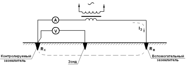
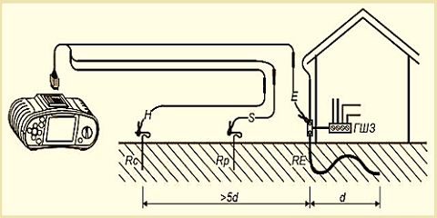
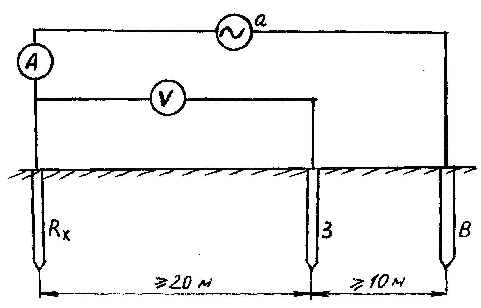
Application of ammeter and voltmeter
The method is as follows. On both sides of the grounding structure to be checked, at an equal distance (about 20 meters), two electrodes (main and additional) are placed, after which alternating current is applied to them. An electric current begins to flow through the circuit formed in this way, and its value is displayed on the display of the ammeter.
A voltmeter connected to the grounding device and the main grounding conductor will show the voltage level. To determine the total ground resistance, you need to use Ohm's law, dividing the voltage value shown by the voltmeter by the current value of which the ammeter shows.
This measurement method is the simplest, but has a low level of accuracy, so other methods are most often used.
Why measure contact resistance (PS)
Electrical installations (EI), as well as cases of electric motors, generators, transformers and other converters must be grounded. The connection of the grounding device to the equipment and power plant is carried out by a bolted connection, which also has a PS.
For reliable operation of the protective shutdown when AC short circuit on the hull of the PS should be checked periodically.
The results of PS testing make it possible to understand what is the probability of electric shock to a person, whether there is a danger of equipment fire when the temperature rises at bad contacts. High PS increases the response time of protective equipment.
How to check the quality of grounding
According to the Electrical Installation Rules, any electrical networks and equipment operating with voltages above 50 volts AC and 120 volts DC must have a protective earth. This applies to premises without signs of high-risk conditions. In hazardous areas (high humidity, conductive dust, etc.), the requirements are even tougher. But in this article we will consider mainly residential buildings. By default, we accept that there should be grounding.
When installing new power lines, grounding will be installed, and the owner of the premises can follow this (or connect it himself). In the case when you live (work) in an already finished room, the question arises: how to check the grounding? First of all, you need to make sure that you have it.Regardless of the formal observance of the PUE, this concerns the life and health of people.


What is the frequency of measurements?
It is necessary to carry out visual inspection, measurements, and, if necessary, partial excavation of the soil according to the schedule established at the enterprise, but at least once every 12 years. It turns out that when to make grounding measurements is up to you. If you live in a private house, then all responsibility lies with you, but it is not recommended to neglect checking and measuring resistance, since your safety directly depends on this when using electrical equipment.

When carrying out work, it is necessary to understand that in dry summer weather it is possible to achieve the most realistic measurement results, since the soil is dry and the instruments will give the most truthful values of ground resistance. On the contrary, if measurements are taken in autumn or spring in wet, humid weather, the results will be somewhat distorted, since wet soil greatly affects the spreading of the current, which, in turn, gives greater conductivity.
If you want the measurements of protective and working grounding to be carried out by specialists, then you need to contact a special electrical laboratory. Upon completion of work, you will be given a protocol for measuring the ground resistance. It displays the place of work, the purpose of the ground electrode system, the seasonal correction factor, and also how far apart the electrodes are. A sample protocol is provided below:

Finally, we recommend watching a video that shows how the grounding resistance of an overhead line pole is measured:
Checking the presence and correct connection of protective earth
At a minimum, you need to look into the switchboard of your apartment (house, workshop).
By default, we accept the condition: single-phase power supply. This will make it easier to understand the material.
There should be three independent input lines in the shield:
- Phase (usually indicated by a wire with brown insulation). Identified with an indicator screwdriver.
- Working zero (color coding - blue or light blue).
- Protective earth (yellow-green insulation).
If the power input is made this way, most likely you have grounding. Next, we check the independence of the working zero and protective grounding among themselves. Unfortunately, some electricians (even in professional teams), instead of grounding, use the so-called zeroing. A working zero is used as protection: a ground bus is simply connected to it. This is a violation of the Electrical Installation Rules, the use of such a scheme is dangerous.
How to check if grounding or grounding is connected as protection?
If the wire connection is obvious, there is no protective ground: you have grounding organized. However, the apparent correct connection does not mean that there is a "ground" and it works. Grounding check includes several steps. We start by measuring the voltage between protective ground and operating zero.
We fix the value between zero and phase, and immediately carry out a measurement between phase and protective earth.If the values are the same - the "ground" bus has a contact with the working zero after the physical ground. That is, it is connected to the zero bus. This is prohibited by the PUE; a rework of the connection system will be required. If the readings differ from each other, you have the correct "ground".
Further measurement of grounding is carried out using special equipment. Let's dwell on this in more detail.
What is the frequency of measurements?
It is necessary to carry out visual inspection, measurements, and, if necessary, partial excavation of the soil according to the schedule established at the enterprise, but at least once every 12 years. It turns out that when to make grounding measurements is up to you. If you live in a private house, then all responsibility lies with you, but it is not recommended to neglect checking and measuring resistance, since your safety directly depends on this when using electrical equipment.
When carrying out work, it is necessary to understand that in dry summer weather it is possible to achieve the most realistic measurement results, since the soil is dry and the instruments will give the most truthful values of ground resistance. On the contrary, if measurements are taken in autumn or spring in wet, humid weather, the results will be somewhat distorted, since wet soil greatly affects the spreading of the current, which, in turn, gives greater conductivity.
If you want the measurements of protective and working grounding to be carried out by specialists, then you need to contact a special electrical laboratory. Upon completion of work, you will be given a protocol for measuring the ground resistance.It displays the place of work, the purpose of the ground electrode system, the seasonal correction factor, and also how far apart the electrodes are. A sample protocol is provided below:

Finally, we recommend watching a video that shows how the grounding resistance of an overhead line pole is measured:
So we examined the existing methods for measuring ground resistance at home. If you do not have the appropriate skills, we recommend using the services of specialists who will do everything quickly and efficiently!
We also recommend reading:
How to measure correctly
Before performing measurements, it is necessary to reduce the number of factors that affect the accuracy of the final results. For analogue instruments with a pointer indicator, this is, first of all, the horizontal arrangement of the case. The magnitude of the error is also affected by the proximity of electromagnetic fields, so the devices should be placed as far as possible from them. This requirement should be observed for all types of meters.


Always calibrate the instrument before testing. On induction, this can be done by turning the handle of the reochord. Some electronic devices have a self-test function, so they will automatically fine-tune to the operating conditions. A four-wire test circuit gives accurate results.
Basic concepts
The resistance of the grounding device (it is also called the current spreading resistance) is directly proportional to the voltage and inversely proportional to the current spreading to the "ground".

There are three types of grounding:
- working.With its help, certain places are grounded, it is used during the operation of electrical equipment;
- lightning protection. Lightning rods are grounded in order to redirect currents to metal structures that occur under the influence of lightning;
- protective. Used to protect against electric shock if someone inadvertently comes into contact with a part that, in normal operation, should not pass current.
There are several methods for measuring the resistance of grounding devices, which will be discussed in more detail. Measurement methods are determined by specialists of the electrical laboratory and depend on the specific operating conditions of the equipment.
Results and conclusions
Grounding is an important element of the electrical circuit, which provides protection against short circuits, electric shock or lightning in one of its sections. The key metric here is resistance: the smaller it is, the more current the circuit will "take away" and the less likely it will be a serious shock or damage to the equipment. Grounding resistance is regulated by two documents: PUE and PTEEP. The first is used to receive a newly commissioned section of the network, the second is used to control an already operated section.
It is impossible to neglect the standards of control, which are designed to check the quality of the grounding and the operation of the circuit under full load conditions. Procedures are performed both immediately after the creation of the circuit, and in the process of its use. The frequency of checks depends on the load on the network and the purpose for which the circuit is used. The norms of resistance are not at all different.There are three types of standards: for power lines, transformers and electrical installations. With an increase in the operating voltage, the maximum resistance increases exponentially. A number of specific indicators are also taken into account (for example, the specific conductivity of the soil). Based on it, you can get the maximum regulated resistance.
The main ways to increase the efficiency of the ground electrode system is to use different conductor configurations. The key task is to maximize the area of direct contact of the circuit with the ground. For this, one or more conductors are used. In the latter case, they can be connected both in series and in parallel.
Also, to measure the resistance of the ground loop, it is important to know the correction factors - for example, when calculating the minimum allowable ground resistance, the specific content of the material in the soil and the re-grounding resistance are also taken into account. To obtain this indicator, you need to use special equipment.


