- Connecting the boiler with a collector
- Protection of a solid fuel boiler against overheating
- Scheme of connecting a solid fuel boiler to a closed heating system
- Connection and setup
- Device
- Features of the scheme of primary-secondary rings
- Universal combined scheme
- natural circulation
- Advantages and disadvantages of pellet boilers
- pros
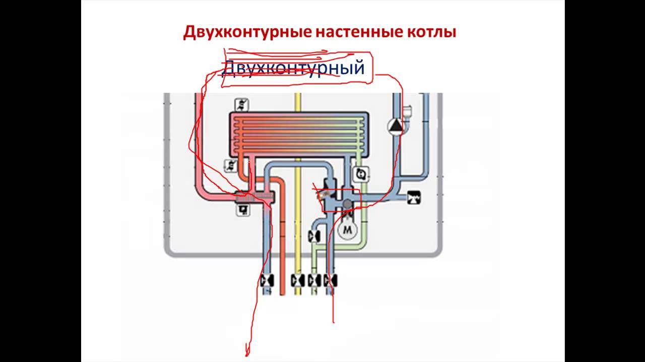
- Wall-mounted boiler piping scheme
- How is the binding of such equipment made?
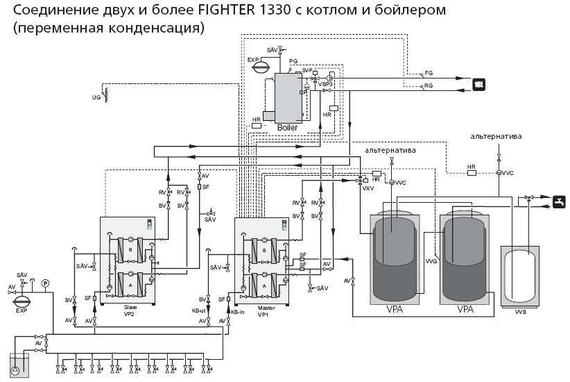
Connecting the boiler with a collector
The above two schemes appeared quite a long time ago. They are divided, depending on the method of assembling the circuit, into tee, manifold and mixed.
Today, the first option is gradually being replaced by a more innovative one - a collector one. Its main advantage is high efficiency. But for the implementation will have to invest a considerable amount.
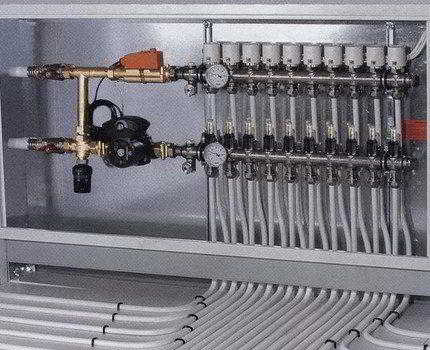
This kind of wiring involves the installation of a special water collector behind the pellet boiler - a collector for heating. Each pipe, radiator or faucet connected to the heating system of the building is connected to this element.
The collector is installed in a specially equipped cabinet. Hot water is supplied to it immediately after being heated by the boiler. Only after that the coolant is distributed through the pipeline.
The advantages of this scheme are obvious:
the owner of the house gets the opportunity to separately control each heating circuit;
stable water pressure is maintained at any point of the heating system;
only one pipe goes to one radiator from the collector, respectively, they can be of a smaller diameter.
It is important to understand that this level of comfort comes at a cost. After all, each individual node of the heating system will have to lay its own pipeline
As a result, this will lead to the need to increase the budget, more consumption of fittings, pipes and other fittings.
The organization of the collector wiring is a complex and scrupulous procedure. Therefore, the best solution would be to entrust the work to qualified specialists, which will avoid mistakes and additional financial expenses.
Protection of a solid fuel boiler against overheating
In a solid fuel boiler, burning fuel, and the boiler itself, have a rather large mass. Therefore, the process of heat release in the boiler has a large inertia. The combustion of fuel and the heating of water in a solid fuel boiler cannot be stopped instantly by cutting off the fuel supply, as is done in a gas boiler.
Solid fuel boilers, more than others, are prone to overheating of the coolant - boiling water if the heat is lost, for example, when the water circulation in the heating system suddenly stops, or more heat is released in the boiler than is consumed.
Boiling water in the boiler leads to an increase in temperature and pressure in the heating system with all serious consequences - the destruction of the heating system equipment, injury to people, damage to property.
Modern closed heating systems with a solid fuel boiler are especially prone to overheating, as they contain a relatively small volume of coolant.
Heating systems usually use polymer pipes, control and distribution manifolds, various taps, valves and other fittings. Most elements of the heating system are very sensitive to overheating of the coolant and pressure surges caused by boiling water in the system.
The solid fuel boiler in the heating system must be protected against overheating of the coolant.
To protect the solid fuel boiler from overheating In a closed heating system that is not connected to the atmosphere, two steps must be taken:
- Shut off the combustion air supply to the boiler furnace in order to reduce the combustion intensity of the fuel as soon as possible.
- Provide cooling of the heat carrier at the outlet of the boiler and prevent the water temperature from rising to boiling point. Cooling should take place until the release of heat is reduced to a level at which boiling water becomes impossible.
Consider how to protect the boiler from overheating, using the heating circuit as an example, which is shown below.
Scheme of connecting a solid fuel boiler to a closed heating system
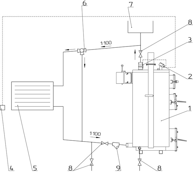
Scheme of a closed heating system with a solid fuel boiler.
1 - boiler safety group (safety valve, automatic air vent, pressure gauge); 2 - a tank with a supply of water for cooling the coolant in case of boiler overheating; 3 - float shut-off valve; 4 - thermal valve; 5 - group for connecting an expansion membrane tank; 6 - coolant circulation unit and boiler protection against low-temperature corrosion (with a pump and a three-way valve); 7 - heat exchanger protection against overheating.
Boiler protection against overheating works as follows. When the temperature of the coolant rises above 95 degrees, the thermostat on the boiler closes the damper for supplying air to the combustion chamber of the boiler.


Thermal valve pos.4 opens the supply of cold water from the tank pos.2 to the heat exchanger pos.7. Cold water flowing through the heat exchanger cools the coolant at the outlet of the boiler, preventing boiling.
The supply of water in the tank pos.2 is necessary in case of lack of water in the water supply, for example, during a power outage. Often a common storage tank is installed in the water supply system of the house. Then the water for cooling the boiler is taken from this tank.
A heat exchanger to protect the boiler from overheating and coolant cooling, pos.7 and a thermal valve, pos.4, are usually built into the boiler body by boiler manufacturers. This has become standard equipment for boilers designed for closed heating systems.
In heating systems with a solid fuel boiler (with the exception of systems with a buffer tank), thermostatic valves and other automatic devices that reduce heat extraction must not be installed on heating devices (radiators). Automation can reduce heat consumption during the period of intensive fuel burning in the boiler, and this can cause the overheating protection to trip.
Another way to protect a solid fuel boiler from overheating is described in the article:
Read: Buffer tank - protection of a solid fuel boiler from overheating.
Continued on next page 2:
Connection and setup
After the installation of the boiler is completed, it is possible to carry out a test switch-on and check. To do this, you need to take the following steps:
- Connect the cable to the power supply.
- Place manually the pellets into the fuel compartment (bunker).
- Turn on the boiler, load the pellets from the bunker into the burner (this is done by pressing the corresponding keys on the dashboard).
- Check on the panel that all indicators light up: turning on the device, starting the burner, presence of a flame, setting the timer, auger operation, internal fan, pump.
- Make sure that there is normal draft and sealing of all docking elements of the boiler.
Enabled by default automatic factory setting of pellet boilers. Experts do not advise relying on them and check all parameters at the first connection. They are all shown on the display. You can also make adjustments and change modes.
If necessary, on the panel you can configure the pellet boiler to suit your requirements: change fuel consumption, operating time, equipment power
It is important to adjust the supply of pellets with the auger from the hopper (it must always be at the level of the upper edge or slightly lower)
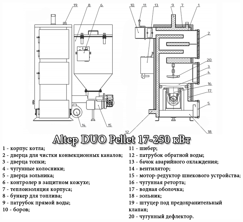
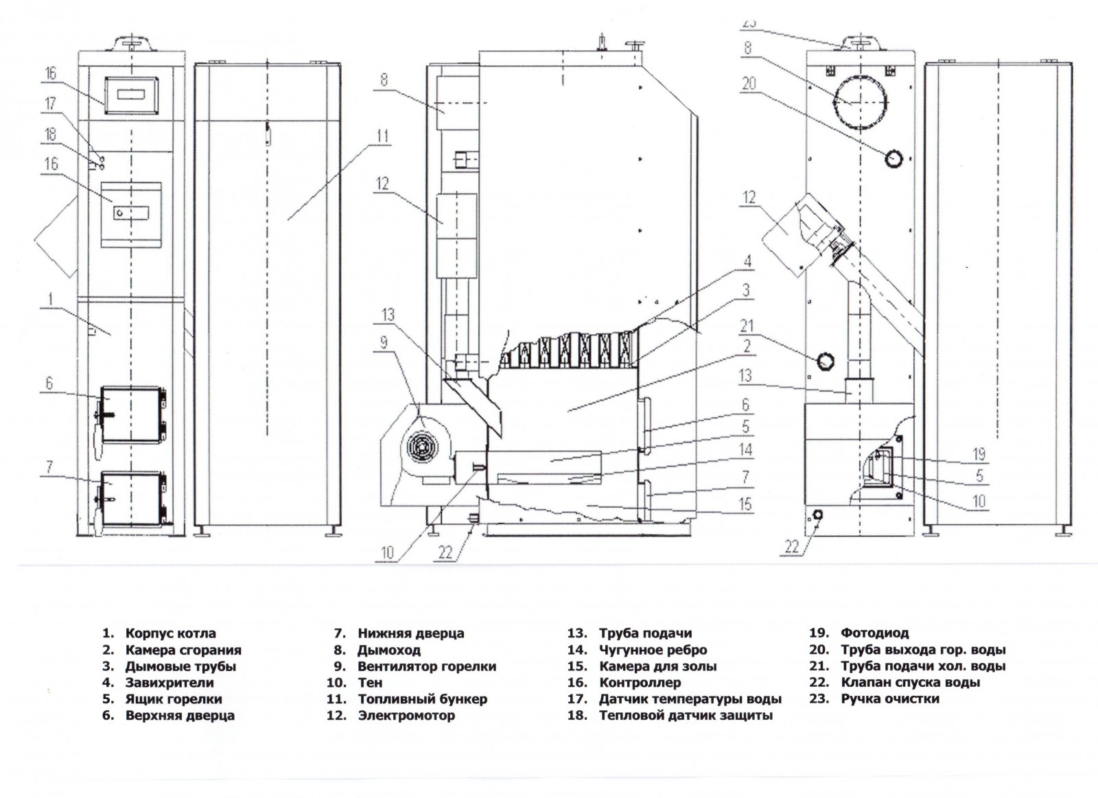
Device
The device of a pellet boiler with the designation of the most important elements and assemblies (click to enlarge)
Before starting work, you should evaluate your strengths.The production of a boiler requires good training, knowledge, skills, and making it much more difficult than gas or electric. It is no coincidence that finished products of this class are very expensive.
In addition to the pellet burner for the boiler. which is almost impossible to do at home, all other structural elements will have to be done independently. It will take a lot of work to achieve the desired result.
Having experience in such work, assembling a heat exchanger and laying out a combustion chamber from fireclay bricks is quite feasible work. The installation of the burner can also be dealt with, but the fuel supply system will have to work hard. This most important node in each case is exclusive. It is necessary to ensure an uninterrupted and reliable supply of fuel pellets to the burner (read about boilers with automatic fuel supply here).
The density of pellets is high, and a large number of them cannot burn at the same time.
Please note: the supply of fuel and air in pellet boilers is always forced. It is almost impossible to ensure the correct mode with manual control, unless you are constantly nearby.
Therefore, the device is equipped with automatic systems, and they cost a lot
It is almost impossible to ensure the correct mode with manual control, unless you are constantly nearby. Therefore, the device is equipped with automatic systems, and they cost a lot.


This is a factor in the high cost of the entire structure. One or more programmers cope with the task without outside interference. Even a small fuel bunker is able to heat a house offline for up to three days.If you assemble a more solid structure with a large supply of pellets, then the period of use can be increased significantly.
Expert tip: It is very important to accurately calculate the air supply. With a lack of air, the pellets may not burn, but smolder, and with an excess, there will be heat losses that will be blown into the atmosphere
Additional costs will also be incurred for the purchase of an engine for the screw mechanism and its automatic connection. Before assembling a pellet boiler with your own hands, you need to draw up drawings of the future boiler, calculate its dimensions depending on the area of \u200b\u200bthe available space for its installation.
The main part of the pellet boiler is the burner
The decision to make a pellet boiler with your own hands is not cheap, but the finished product will cost even more. The main element of the device is a burner, which is purchased separately.
Similar to factory models, the focus is on assembling the body and fitting all the components. Assembly kit includes:
- Sheet steel 4-6 mm for the manufacture of the boiler body.
- Bunker material. It can be made from sheet metal (1-2 mm thick will be enough), plywood, wood.
- Screw. It is selected according to size or, with existing skills, it is done independently.
- Chimney pipes. Metal or asbestos and mounting kit.
- Control system. Provides automatic control over the operation of the boiler.
- Engine for the operation of the screw mechanism.
- Pipes for heat exchanger. Square sections are recommended.
- Pipes and fittings for connecting the heating system.
- Chamotte brick, if the combustion chamber is made stationary.
- Grate. It will provide air access to the place of combustion.
Features of the scheme of primary-secondary rings
This scheme provides primary ring organization
, through which the coolant must constantly circulate. Heating boilers and heating circuits are connected to this ring. Each circuit and each boiler is a secondary ring.
 Another feature of this scheme is the presence of a circulation pump in each ring. The operation of a separate pump creates a certain pressure in the ring in which it is installed. The assembly also has a certain effect on the pressure in the primary ring. So, when it is turned on, water leaves the water supply pipe, entering the primary circle and changing the hydraulic resistance in it. As a result, a kind of barrier appears on the way of the coolant movement.
Since the return pipe is first connected to the circle, and after it the supply pipe, the coolant, having received considerable resistance from the supply pipe, begins to flow into the return pipe. If the pump is turned off, the hydraulic resistance in the primary ring becomes very small and the coolant cannot swim into the boiler heat exchanger. The binding continues to work as if the unit was not turned off at all.
For this reason no need to use one complex automation to turn off the boiler
. The only thing you need is to install a check valve between the pump and the water return pipe. The situation is similar with heating circuits. Only the supply and return lines are connected to the primary circuit in the opposite order: first the first, then the second.
It is advisable to include no more than 4 boilers in such a scheme. The use of additional devices is impractical.
Universal combined scheme
This system has the following binding:
- Two common collectors or hydrocollectors
. The supply lines of the boilers are connected to the first one. To the second - the return line. All lines have shut-off valves. Circulation pumps are located on the coolant return pipes. - The diaphragm tank is connected to a large return manifold.
- The indirect heating boiler is the link between the two collectors. on the pipe, which connects the boiler to the supply manifold
, there are a circulation pump and a shut-off valve. The pipe connecting the boiler to the return manifold also has a valve. - The safety group is installed on the coolant supply manifold.
- The make-up pipe is connected to a collector, which is located on the hot water supply line. To prevent leakage of hot coolant through this pipe, a check valve is placed on it.
- A certain number of small hydrocollectors (there may be two, three or more)
. Each of them is connected to the aforementioned common collectors. These hydrocollectors and large reservoirs form primary rings. The number of such rings is equal to the number of small hydrocollectors. - Heating circuits depart from small hydrocollectors. Each circuit has a miniature mixer and a circulation pump.
A solid fuel boiler always requires constant attention from the residents of the house, because after the firewood loaded into it has burned out, the heat stops flowing into the heating radiators. Of course, the heat accumulator can improve the situation, but after it cools down, the heating system will cease to be a heating system. Combined can make life easier for owners of a private house wood-gas heating boilers or two boilers, one of which runs on solid fuel and the other on gas.


Any of these two options makes it possible to obtain the desired heat in the case when there is no firewood left in the firebox, but there is still gas in the cylinder. The gas-firewood unit is suitable for those people who do not want to spend much effort and money on organizing complex tying. However, practice shows that it is better to combine two different boilers. The least advantage of this approach lies in the constant operation of the network, regardless of the possible failure of any of the devices. If the gas-firewood device breaks down, the system stops working and it will be cold in the premises of the house.
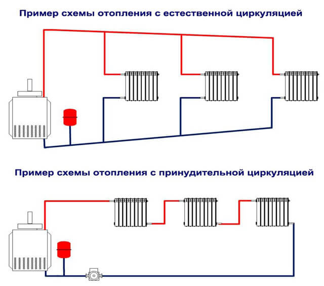
natural circulation
The gravity system is characterized by complete energy independence: its operation is provided by atmospheric pressure. Instead of a bulky safety group in the piping of a single-circuit boiler, an expansion tank is sufficient. It is advisable to install a vent on the filling in front of the boiler heat exchanger: this will make it possible to completely drain the water into the sewer or drainage well. Usually such a need arises in the event of a long departure, or when the gas supply is cut off. As a result, the system is protected from defrosting.
The individual nodes of the system are located as follows:
The tank is recommended to be installed above all other elements.
The filling located immediately after the boiler is positioned in a vertical direction (a slight angle is allowed)
Thanks to the accelerating section, the water heated in the heat exchanger rises to the top filling point of the supply.
It is important to maintain a constant slope when laying the filling after the tank.As a result, the cooling water will return by gravity: air bubbles will be able to exit inside the expansion tank.
The boiler must be lowered as low as possible
The best place to place the heater is in a pit, basement or basement. Due to the difference in height between the heat exchanger and the heaters, the proper level of hydraulic pressure is ensured, which ensures the circulation of water in the circuit.

Some features of the arrangement of the inertial heating system:
- For the inner diameter of the filling, an indicator of 32 mm is selected. If plastic or metal-plastic pipes are used, then the outer diameter is 40 mm. Due to the significant cross section, compensation of the minimum hydraulic head is achieved, due to which the coolant moves.
- The gravitational system sometimes includes a pump: however, this does not mean that the circuit loses energy independence. In this case, the pump is mounted not in the filling gap, but parallel to it. To connect individual tie-ins, a ball-type check valve is used, which is characterized by very low hydraulic resistance. A ball valve is also installed. In the event of a pump stop, the bypass is closed, which maintains the operability of the natural circulation circuit.
Advantages and disadvantages of pellet boilers
As noted above, pellet boilers are a fairly new type of heating devices for the Russian market. However, they have good potential to strengthen their position due to some significant advantages over diesel or gas boilers.
pros
The main advantages of pellet boilers are:
-
Pellets have the lowest percentage of ash content among other solid fuels such as wood or coal. The CO2 content in flue gases is also very low.
-
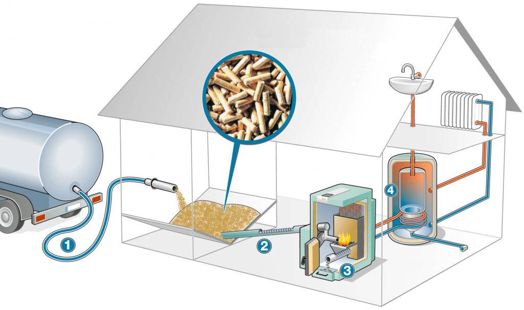
A pellet boiler can essentially be called a long-burning heating device. The presence of automation and a bunker for storing fuel allows you to create an almost fully automated heating system in your country house or in the country.
-
The efficiency of pellet boilers with an open type burner reaches 95%. When using torch-type burners, the efficiency is slightly lower and is about 90%.
-
The high price of pellet boilers is offset by their long service life. On average, the service life of heating devices powered by fuel pellets is about 20 years.
-
As a rule, using a pellet boiler for heating a private house is quite expensive. For example, a low-power one costs around 250,000 rubles.
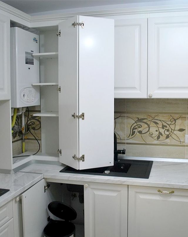
Wall-mounted boiler piping scheme
The installation location of the boiler must meet the following requirements:
- Requirements of the attached technical documentation for the boiler;
- Gas project requirements for gas boilers.
The accompanying documentation always clearly reflects the dimensions of the distances to the enclosing structures. Decisions on the placement of electric, solid fuel and liquid fuel heat generators can be made by the owner independently, in compliance with the requirements of equipment passports.
Gas boilers of wall and floor type are installed strictly in compliance with the requirements of the agreed project. Oil-fired boilers, when replacing the burner and switching to natural gas, also require the implementation of the project - it is possible to change the location point.
Wall-mounted boilers have two ¾ inch (DN20) external threaded pipes.For piping the boiler with a full set of internal equipment, the following products are used:
- Ball valve ¾ with squeegee American - 2 pcs.;
- Coarse mesh filter, internal threads ¾ - 1 pc.;
- Coupling brass Du20 (3/4 inches);
- Adapter of the selected pipe system Du20x3/4 HP (external thread).
Ball valves are installed with spurs towards the boiler nozzles. This allows you to turn off and remove the boiler for preventive maintenance without releasing the system from water. The filter is designed to protect the heat exchanger from large fractions - scale, sand, and the like.


Heating pipelines - polypropylene, metal-plastic, copper, cross-linked polyethylene - are connected to adapters 20x3/4. Next, a heating system of various configurations is mounted:
- Single pipe;
- Two-pipe;
- Collector;
- Combined.
It should be noted that the volume of the built-in expansion tank in the boiler does not always correspond to the volume of the heating system. For verification, you always need to carry out a verification calculation.
To do this, the volume of coolant in the following equipment is calculated:
- Boiler (the capacity of the heat exchanger is indicated in the passport);
- Heating radiators - internal volume;
- Internal volume of pipelines.
The internal volume of water in the radiators is indicated in the technical documentation for the product. One section of an aluminum radiator with a standard height of 500 mm (distance between connection centers) contains 300 - 350 ml of coolant, in the section cast iron radiator MS-160 - about 1.5 liters.
The internal volume of pipes is calculated by the flow area of the pipe, multiplied by the length of the pipeline (cylinder volume).
The volume of the built-in expander must be at least 10% of the total volume of the system. Otherwise, an additional membrane expansion tank must be installed.
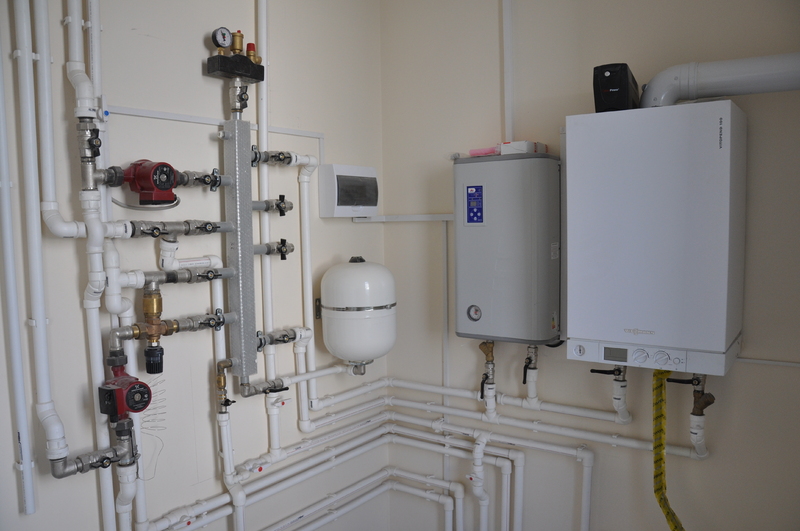
In the absence of built-in equipment, a typical piping scheme consists of shut-off valves, a filter, an expander, a circulation pump, and a safety group. The make-up (filling) line from the cold water supply is mounted only to single-circuit wall-mounted boilers. Double-circuit boilers are connected to water, have a corresponding switch for replenishing the system.
The safety group is installed at the top of the tie knot. The circulation pump is recommended to be installed on the return pipeline, which has a lower temperature. This creates the conditions for a longer pump life.
When installing the pump, you must follow the rules for installing equipment with a "dry" and "wet" rotor. Products with a "dry" rotor can be installed in any spatial position, with a "wet" rotor - strictly with a horizontal arrangement of the rotor. This is due to the fact that the wet rotor bearings are cooled by the pumped liquid.
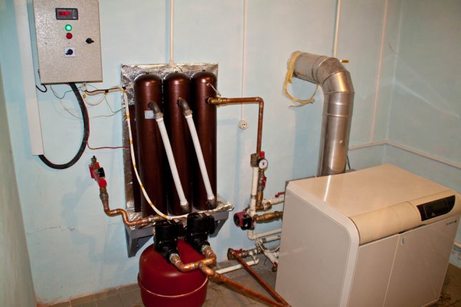
How is the binding of such equipment made?
The general installation scheme for heating boilers consists of the following series of steps:
- installation of distribution combs;
- installation of appropriate pumping circuits for each consumer;
- installation of safety equipment;
- installation of an expansion tank;
- installation of shutoff valves;
- connection of the boiler with the supply and return circuits;
- filling the circuits with coolant;
- pressure testing of equipment and checking its operation.
In practice, everything depends on the power of the equipment, the number of consumers, the design features of the boiler, etc. It should be noted that rather high requirements are imposed on the piping of pellet boilers. Firstly, because the moisture content of the fuel must remain acceptably low, and secondly, because both the fuel and the coolant are heated to very high temperatures. Poor-quality piping can lead to the fact that the operating conditions of the equipment will be violated, and the boiler will quickly fail.
In accordance with fire safety standards, it is recommended to use non-combustible metal pipelines for piping pellet boilers. The use of polypropylene structures in practice is not only dangerous, but also unprofitable, since the temperature of the coolant at the outlet of the boiler often exceeds the performance of polymeric materials. As a result, pipelines will have to be replaced in a couple of years.
Pellet boiler is a rather complicated device. Experts strongly do not recommend inexperienced beginners to engage in the installation and strapping of such devices. However, knowledge of the main stages of strapping and some of the nuances of this process will allow you to effectively control the work of the invited team of installers.
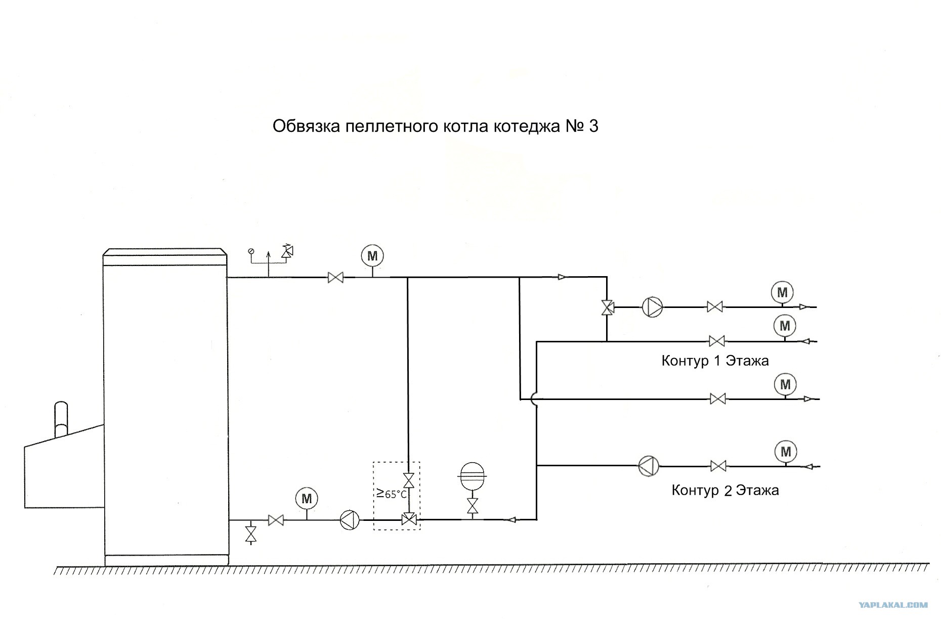
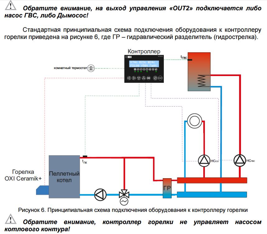
The diagram shows one of the options for piping a pellet heating boiler: 1 - MK pump; 2 - mixing valve MK; 3 - pump TK1; 4 - mixing tap TK1; 5 - water recirculation in TC1; 6 - pump TK2; 7 - mixing tap TK2; 8 - water recirculation in TC2; 9 - DHW pump; 10 - hot water heat exchanger; 11 - supply of running water to the hot water supply
To piping a pellet boiler, you must:
- perform boiler installation;
- connect the appropriate burner (if a combined boiler model is used);
- install a pellet hopper;
- connect the auger for fuel supply;
- connect the automatic boiler control panel.
After that, you should run:
- Installation for the boiler supply of a safety group, which includes a pressure gauge, an automatic air vent and a relief valve.
- Installation of a thermal valve sensor, if it is provided for by the design of the model;
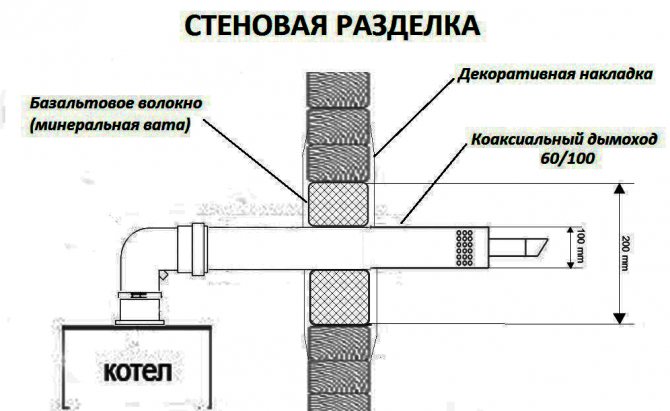
- Installation of a chimney, the diameter and height of which meet the technical requirements.
- Installation of a system of devices for maintaining a reverse flow: two pressure gauge valves for supply and return, a circulation pump and a thermal head.
- When there is a high probability of sudden power outages, it is recommended to supplement the system with a suitable UPS model.
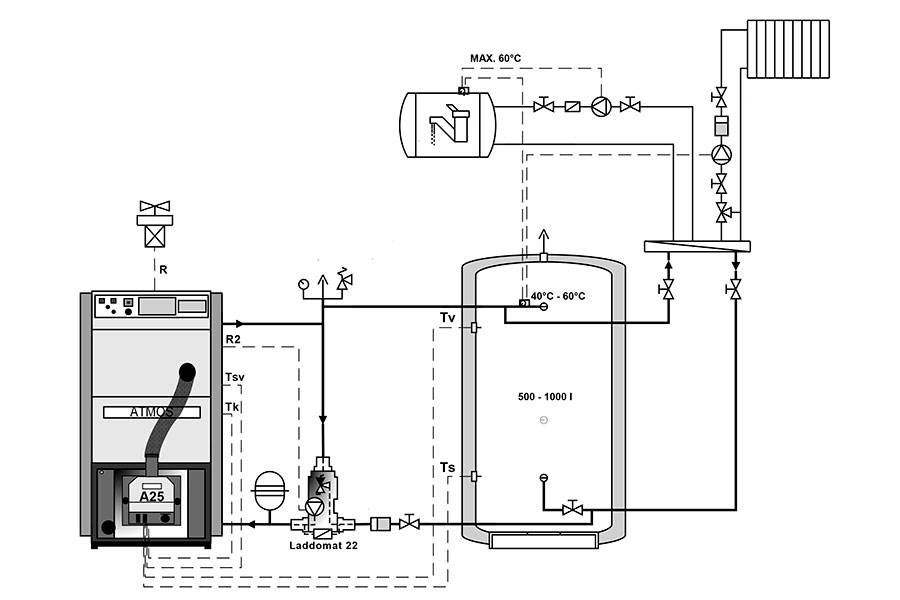
Backflow support allows you to control the level of heating of the coolant before it enters the system. Until the return temperature reaches the required level (usually 60 degrees and above), the coolant will remain within the small circulation circle. Only when the coolant is heated to the required level, the thermal head opens and cold coolant begins to flow through it, and hot coolant begins to circulate in the main circle.


Under no circumstances should a pellet boiler with a low heat carrier temperature be used. A temperature of 55 degrees is the so-called "dew point", upon reaching which a significant amount of condensate is formed. As a result, the amount of soot in the chimney and also on the heat exchanger can increase significantly. The equipment will require additional maintenance efforts, and its power will noticeably decrease.
This is what the combustion chamber of a pellet heating boiler looks like after exposure to an excess amount of condensate that appears due to errors during the installation of the recirculation system
The process of tying a combined pellet boiler is presented in detail in the video:
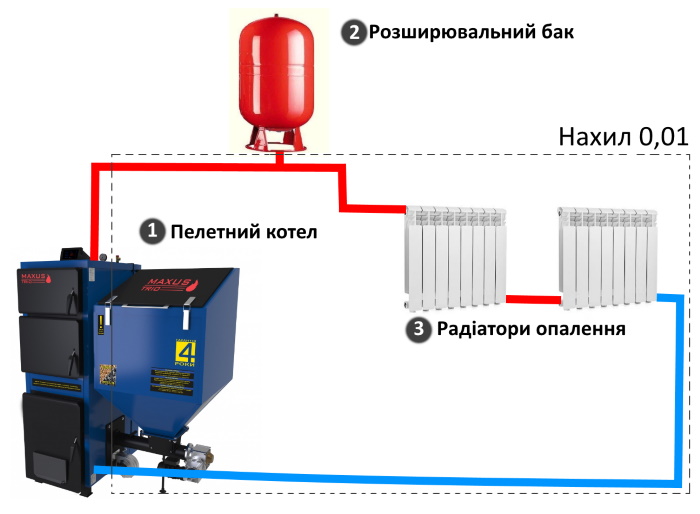
Many manufacturers of pellet boilers recommend supplementing the design with a special storage tank that allows you to accumulate heat. Fuel savings in this case can reach 20-30%. In addition, the use of a storage tank allows you to avoid overheating of the boiler and achieve the highest possible efficiency.