- Check valve installation rules
- Ventilation in an apartment or house
- Rules and Regulations
- Artificial and natural air exchange
- Purpose and place of installation
- How to install the valve correctly
- Purpose and principle of operation
- Features of installing a locking device
- Self-manufacturing
- Options for working connection diagrams
- Balancing
- boiler part
Check valve installation rules
When deciding where to put the check valve for heating, you need to be guided, first of all, by the requirements of the project. If the wiring diagram requires a check valve, it must be installed in the right place and taking into account all requirements and standards. As a rule, such fittings are installed at the time of piping the heating boiler.
Please note that for the correct installation of the check valve, you need to correctly select its type in accordance with the operating pressure and temperature of the coolant
In addition, it is important to mount the product in the manner indicated by the manufacturer in the technical data sheet for the valve. As a rule, the location of the check valves is determined at the design stage of the heating system.
As a rule, the location of the check valves is determined at the design stage of the heating system.
Installing check valves on the heating system allows you to cope with several tasks at once. First of all, such devices make it possible to prevent negative consequences for the heating system in case of emergency situations. In addition, it is a kind of insurance against unnecessary repair costs in the future. Another important point is the consistency of the operation of various devices looped into one system. It is achieved just by installing shut-off valves. They also install a make-up valve for the heating system, which in certain cases is simply necessary.
Thus, if you are worried about the durability and reliability of the heating and do not want to have additional costs in the future, then you should definitely consider having a check valve in the heating circuit.
Ventilation in an apartment or house
On the one hand, air exchange in an apartment or house must comply with the standards established for residential facilities, and on the other hand, it must obey the laws of physics. Therefore, it is not always possible to get by with trivial solutions and sometimes it is necessary to install a check valve designed to allow flow in one particular direction.
Rules and Regulations
The main document to be guided by when designing ventilation both in an apartment and in a private house is SP 54.13330.2016. This is an updated version of SNiP 31-01-2003 " Residential multi-apartment buildings". The scheme of air movement through a residential facility of any layout should be drawn up based on the provisions of paragraphs. 9.6 and 9.7 of this set of rules.
Table 9.1 sets the air exchange rates for various types of premises.Designers and owners of commercial real estate must strictly follow these parameters.
The inflow of outdoor air should occur in living rooms and the kitchen, and the outflow should occur from the kitchen, bathroom and technical rooms.
Residents can install ventilation with a lower throughput, focusing on microclimate indicators:
- Humidity that can be measured with a hygrometer. Air oversaturated with water leads to the formation of fungus on the wallpaper and ceiling, as well as smudges on the windows.
- Carbon dioxide, the concentration of which can be measured with a gas analyzer. Without the device, the lack of oxygen can be clearly felt immediately upon entering the room from the street.
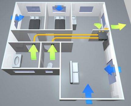
Air circulation can be natural or forced. It depends on many factors, including the area, number of storeys, location of rooms and technical premises.
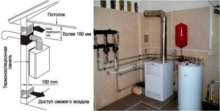 System gas boiler room ventilation autonomous. According to safety requirements, it cannot be combined in any way with the air circulation inside the house.
Thus, in any housing there are points of inflow and removal of air, and the situation is unacceptable when an outflow occurs through the inlet, and air mass enters through the ventilation shaft.
This leads to a violation of sanitary and hygienic, fire and other standards and can seriously worsen living conditions.
Artificial and natural air exchange
Sometimes a situation arises when it is necessary to force the removal of air from the following rooms:
- Kitchen. During cooking, intense evaporation may occur. To prevent it from spreading throughout the kitchen and further to other rooms, an extractor hood is installed above the stove.Its work allows you to send polluted air directly into the ventilation shaft.
- Bathroom. When taking a shower, the air is saturated with water vapor. To quickly remove it, turn on the ventilation unit, since otherwise the appearance of mold or the peeling of plastic and tiles will occur much more intensively.
- Workshop. During carpentry or other work, a suspension is often formed, which can be harmful to human health. To do this, run fans or hoods, which are located near the source of pollution.
Turning on forced ventilation is temporary, as it consumes a lot of electricity and creates noise during operation.
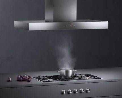
A powerful hood is able to take all the air above the stove, but when turned off, it does not let air into the ventilation duct at all
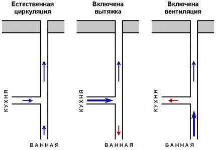
After the introduction of devices for forced ventilation, a problem arises with the natural circulation of air through the obstacle that has arisen. If an ordinary blade fan still somehow passes the air flow, then the hoods, as a rule, minimize the passage to unacceptably low rates.


Stopping natural circulation can cause local problems in the room. For example, high humidity will occur in the kitchen and windows will “flow” in winter. But even worse, the movement of air around the house will be disrupted, which will affect all rooms.
Installing a hood can have another negative effect if this device is integrated into the general duct ventilation. Air exchange obeys the law of balance conservation: at any given time, the amount of incoming and outgoing air is the same.
It follows from this that an increase in pressure at one of the points leads to a change in the readings at others. The main thing here is to exclude the possibility of reverse flow.
An increase in the power of the air flow leads to a redistribution of pressure inside the duct ventilation. In the absence of check valves, reverse formation is possible
To solve both problems, a check valve is installed. Given the fact that modern air ducts for residential premises have standard dimensions, self-assembly of such an element is not very difficult.
Purpose and place of installation
Closed heating systems operate under a certain pressure. A significant increase in operating pressure leads to equipment failure. Connections may leak, plastic parts and elements may burst. In the most unfavorable situations, the boiler heat exchanger may explode. This is already very dangerous and threatens not only with a floor filled with hot coolant, but also with burns. After all, the temperature is unbearable.
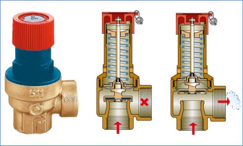
The overpressure relief valve must protect the heating system from excessively high pressure. As long as the parameters of the system are within the normal range, it does not manifest itself in any way. Although from the moment the boiler starts, the pressure in the system gradually increases, the expansion tank compensates for it, maintaining a stable state of the system. But maybe he does not do this endlessly, although, with the right calculation, he is enough for regular situations. If the expander does not cope with the task, the pressure begins to rise. When it exceeds the threshold, then the overpressure relief valve is activated.It simply releases part of the coolant, thereby stabilizing the emergency.
That is, the overpressure relief valve in the heating system works in emergency situations. Therefore, it is also called "emergency". And also - "discharge", "bleed", "protective" and "subversive". All these are the names of the same device.

What does the safety (emergency) valve for heating look like?
As is clear from the description, when the pressure rises above a certain limit, a certain amount of coolant is simply released from the system. If you came to the boiler room, and a puddle formed under the emergency valve, it means that there was an emergency situation during which the pressure increased. No other alarm
So these tracks are worth paying attention to. It is worth immediately checking the performance of the valve itself and the membrane tank. Most likely they are the reason
If you do not pay attention to these symptoms, after a while you may encounter problems: either something will “fly” in the system, or the boiler will break
Most likely, the reason is in them. If you do not pay attention to these symptoms, after a while you may encounter problems: either something will “fly” in the system or the boiler will break.

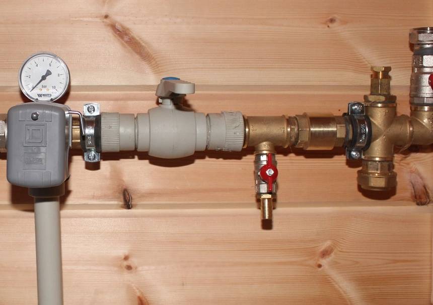
The installation location of the emergency heating valve is on the supply pipeline, not far from the boiler
Of all the equipment of an individual heating system, the most dangerous is the boiler. Therefore, the overpressure relief valve is placed either directly on the boiler itself (if there is an appropriate outlet for the installation) or on the supply line immediately after the boiler. The distance is small - 20-30 cm from the body.If the boiler does not have this type of fitting (indicated in the description), then it is installed in the so-called safety group or placed separately. The safety group is placed on the outlet from the supply line immediately after the boiler (before the first branch and any other device), on which a pressure gauge, an automatic air vent and an overpressure relief valve are installed.
How to install the valve correctly
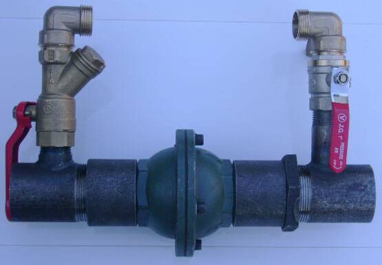
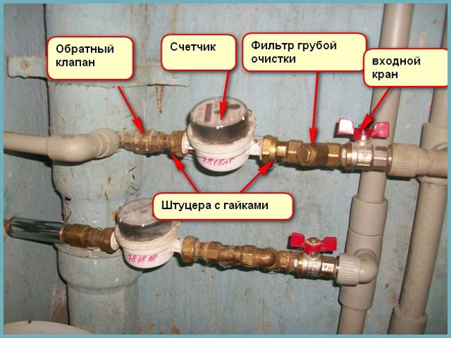
The easiest way is to install a check valve in a coupling version. It is suitable for embedding in heating and water supply systems both in apartments and in private houses.
To protect metering devices and other network segments from the occurrence of water hammer, you must perform 3 simple steps:
-
Choose a location. In apartments, a water return valve is usually inserted to the meter or in front of the heating boiler.
-
-
Take the fittings of the required diameter and wrap the sealant on the thread: tape, thread or linen.
-
Fix the device with fittings, open the water tap and check the connection for leaks.


Let's give some advice:
-
In the circuit of the working water supply system, the valve is installed in front of the pumping station. To do this, a place is chosen on the pipe where a break is made, and connected with a locking device.
-
As part of the sewer, the valve will help prevent the flow of waste and sewage in the opposite direction. Installation is carried out on pipes of suitable diameter using a tie-in. The valve diameter can be 50-100 mm. Cast iron or plastic connections are made with a special adapter.
-
In a single-circuit heating system, a valve is necessary to create coolant pressure due to heating, without using a pump.Installation is carried out similarly to the process of installing a valve on a water supply system.
Sometimes even reliable shut-off valves fail. If a breakdown occurs, you need to learn how to disassemble the check valve. This is not difficult. First you need to block the flow of working fluid and drain it from the system. Then you should unscrew the nuts, dismantle the flanges or fittings. The final stage is the removal of the locking unit and the replacement of failed parts. Assembly is carried out in reverse order.
Purpose and principle of operation
The main function that a check valve for water performs is that it protects the water supply system from the critical parameters of the flow of liquid transported through the pipeline. The most common cause of critical situations is the shutdown of the pumping unit, which can lead to a number of negative phenomena - draining water from the pipeline back into the well, spinning the pump impeller in the opposite direction and, accordingly, breakdown.
Installing a check valve on water allows you to protect the plumbing system from the listed negative phenomena. In addition, the water check valve prevents the consequences that water hammer causes. The use of check valves in pipeline systems makes it possible to make their work more efficient, as well as to ensure the correct functioning of the pumping equipment that such systems are equipped with.
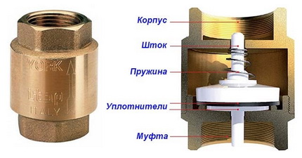
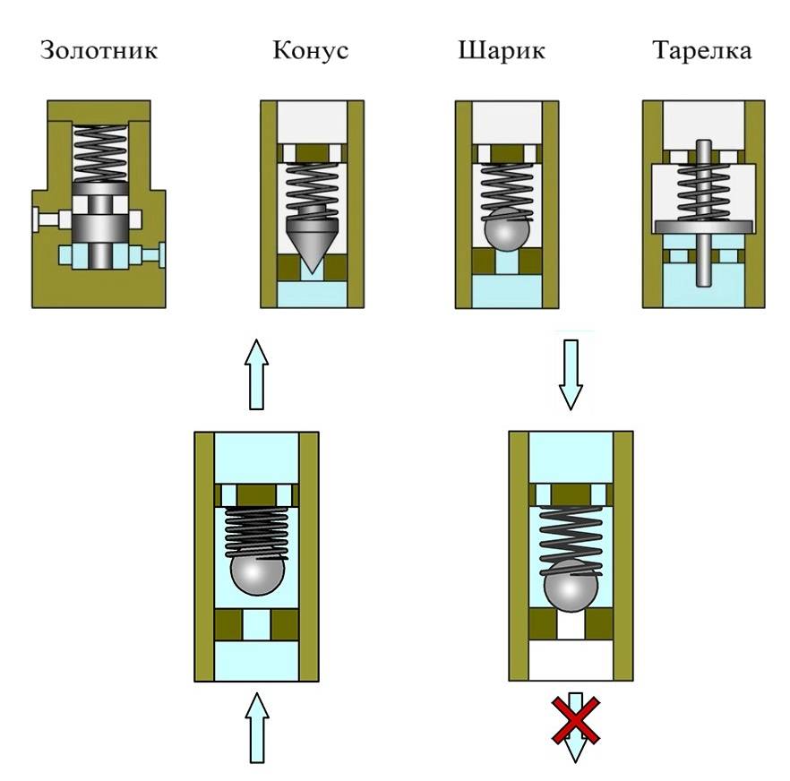
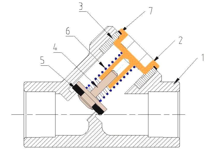
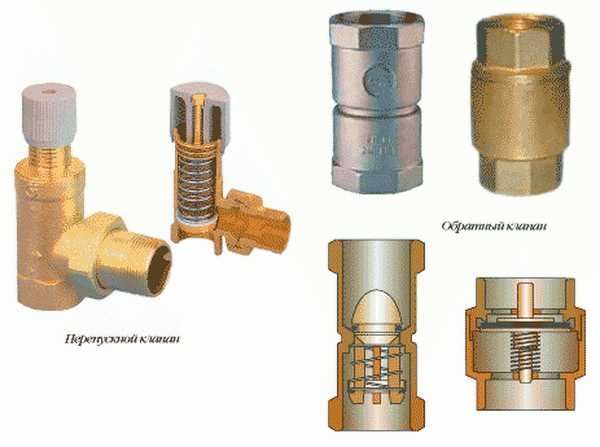
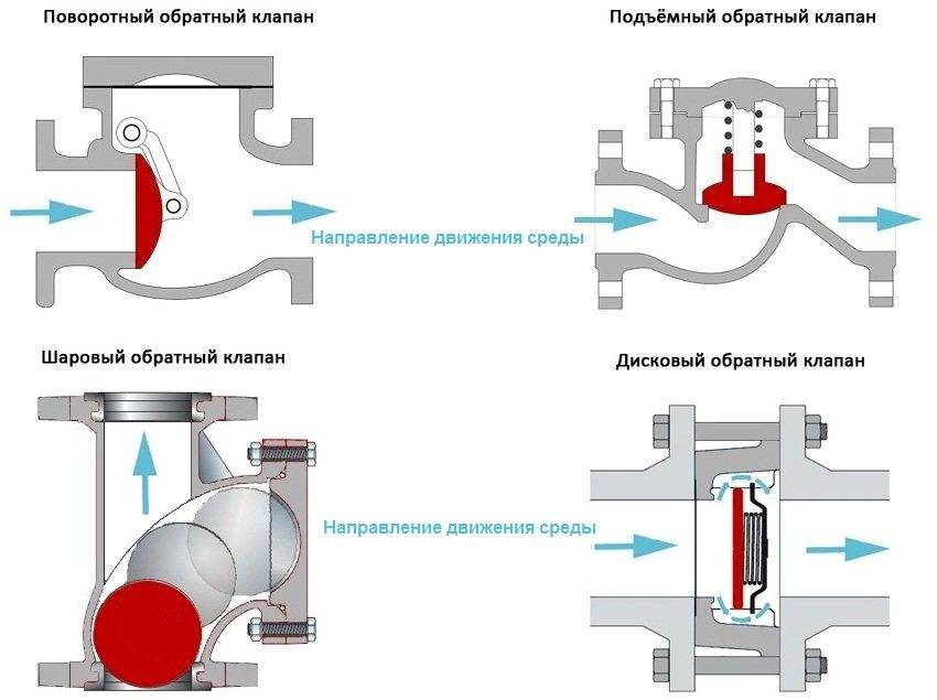
The principle of operation of the check valve
The principle of operation of the check valve is quite simple and is as follows.
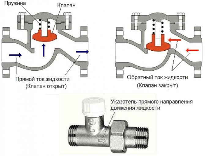
- The flow of water entering such a device under a certain pressure acts on the locking element and depresses the spring, with which this element is held closed.
- After compressing the spring and opening the locking element, water begins to move freely through the check valve in the required direction.
- If the pressure level of the working fluid flow in the pipeline drops or the water begins to move in the wrong direction, the spring mechanism of the valve returns the locking element to the closed state.
By acting in this way, the non-return valve prevents the formation of unwanted backflow in the piping system.
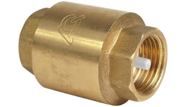
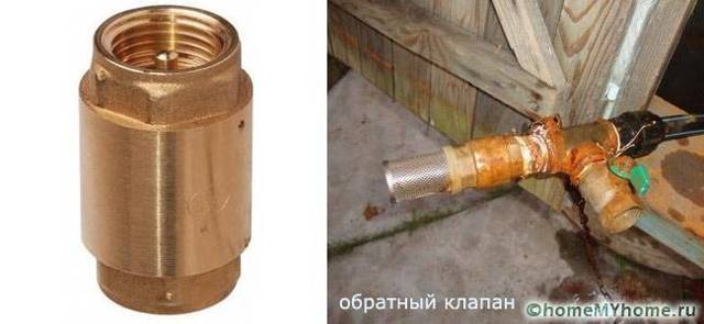
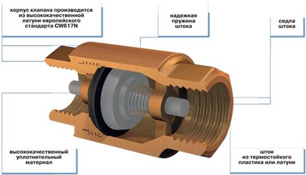
Spring Type Check Valve with Nylon Poppet
When choosing a model of a valve installed on a water supply system, it is important to know the regulatory requirements that manufacturers of pumping equipment impose on such devices. The technical parameters by which, in accordance with these requirements, a check valve for water is selected are:
- operating, trial and nominal closing pressure;
- landing part diameter;
- conditional throughput;
- tightness class.
Information on what technical requirements the check valve for water must meet is usually contained in the documentation for pumping equipment.
Check valve, single disc, coupling
To equip domestic water supply systems, spring-type check valves are used, the diameter of the conditional passage is in the range of 15–50 mm. Despite their compact size, such devices demonstrate high throughput, ensure reliable operation of the pipeline, low noise and vibration levels in the pipeline system on which they are installed.


Another positive factor in the use of check valves in the water supply system is that they help reduce the pressure created by the water pump by 0.25–0.5 atm. In this regard, the check valve for water allows you to reduce the load both on individual elements of pipeline equipment, and on the entire water supply system as a whole.
Features of installing a locking device
The best option for installing a shut-off valve is to repair an apartment or build a house. It is at this stage that it is easiest to design its location and calculate the required pipe length. In this case, the locking device will be mounted during the assembly of the entire sewer system.
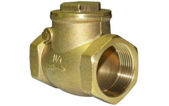
Plastic check valves for arranging internal sewer networks are produced with shaped elements that facilitate installation and decorate the places of passage through building structures
Most often it happens that no one plans to do repairs, but the valve must be installed. Then you should choose this device, based on the realities of your sewer system. If the shut-off valve has already been selected and purchased, you can deal with the issue of its installation.
There are 2 options:
- do everything yourself;
- call a plumber.
Depending on the material of the pipes in the apartment / house, the installation methods and the list of works required for this will differ. The price of the issue will also differ - for cast-iron fittings, removing a part for installing a shut-off valve in this place is much more expensive than a similar amount of work with plastic materials.
When the option with the invitation of the master is chosen, then only funds will be required to pay for his services.It is also advisable to control the work and check the quality of the installation so that there are no problems later. It is best to contact a plumber serving the house / assigned to a certain territory.
The non-return valve is connected to the plastic sewer pipeline using a connecting element designed to exceed the standard pressure in the network. He does not allow leaks.
If you decide to do everything on your own, then you need, first, to look at the installation theory or read a brief instruction on installing a check valve on the sewer system.
Firstly, you will need to check the purchased device in action before installing it. To do this, you can use, for example, a jet of water from a tap. After testing the performance of the valve and making sure that it passes water in only one direction, you can proceed to the next step.
The second step is to measure the length of the reverse device and mark the place of its installation, taking into account these dimensions.
It is important here that there is free access to the valve - periodically it will be necessary to carry out an audit
When everything is marked out, it is necessary to remove / cut off a section of the pipe, in place of which a locking device will be put. When installing, you must use an o-ring and sealant or fum tape to ensure a secure connection and prevent leakage.
To connect a check valve at the point of change in the direction of the sewer branch, elbows with seals are used. They allow you to create an optimal bending angle and ensure a reliable connection.
Similarly, you have to do with the rest of the shut-off valves, if you plan to install separate shut-off devices for each plumbing fixture.
You should correctly position the valve using the instructions that came with the device, or you can look at the red arrow indicating the direction of movement of sewage.
When all the joints of the sewer pipe with the shut-off valve are securely insulated, you should check the work carried out in action by opening the tap or draining the water in the drain tank. If nothing leaks at the installation site, then everything is done with high quality and you don’t have to worry.
The option with separate blocking devices on each plumbing fixture is more convenient - this way the apartment will be more reliably protected in the event of a sewer blockage
When installing a shut-off valve in a common sewer pipe in a country house / cottage, you should also ensure free access to it, even if it is located outside. The outer part of the sewer, together with the device and other fittings, should be provided with a heating cable or a thermal insulation system.


Self-manufacturing
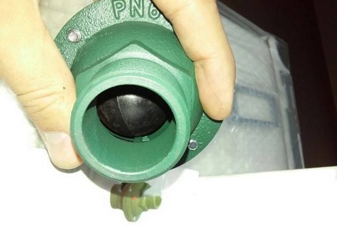
The check valve for water can be assembled by hand using the necessary set of consumables.

To implement a creative idea, you will need:
- body made of metal tee with thread;
- saddle for constipation;
- hard spring;
- a metal ball of the appropriate diameter;
- plug;
- sealing tape;
- tool kit.
The assembly of the structure is carried out in stages.
- First, the coupling is screwed in with the expectation to block the clearance of the side pipe by more than two millimeters.
- A ball supported by a spring is inserted into another hole.
- The plug is installed.
- Connections are sealed with a sealant.
The flow from the sleeve depresses the ball, opening the gap for flow in the forward direction. When the pressure drops, the ball is pressed back, closing the gap with flow blocking.
Options for working connection diagrams
Heating systems are very diverse and the presence of a check valve is not necessary in all. Consider several cases when its installation is necessary. First of all, a check valve must be installed on each of the individual circuits in a closed circuit, provided that they are equipped with circulation pumps.
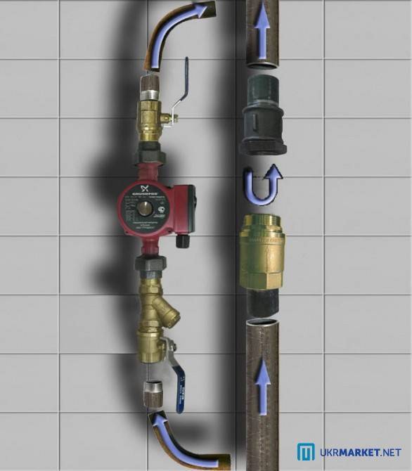
Some craftsmen strongly recommend installing a spring-type check valve in front of the inlet pipe of the only circulation pump in a single-circuit system. They motivate their advice by the fact that in this way pumping equipment can be protected from water hammer.
This is in no way true. Firstly, the installation of a check valve in a single-circuit system is hardly justified. Secondly, it is always installed after the circulation pump, otherwise the use of the device loses all meaning.
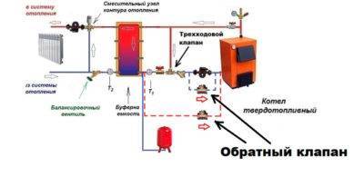
If two or more boilers are included in the heating circuit, the occurrence of parasitic flows is inevitable. Therefore, the connection of a non-return valve is mandatory.
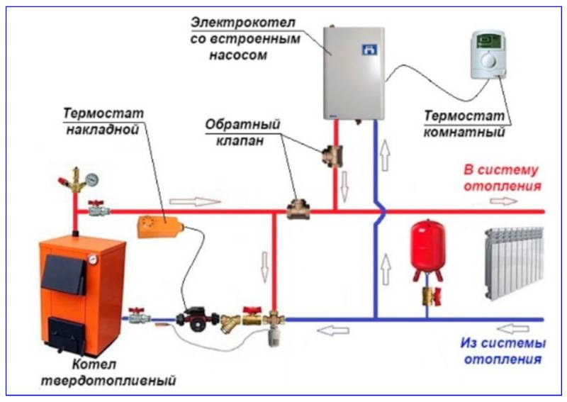
For multi-circuit systems, the presence of a reverse-acting shut-off device is vital. For example, when two boilers are used for heating, electric and solid fuel, or any others.
When one of the circulation pumps is turned off, the pressure in the pipeline will inevitably change and a so-called parasitic flow will appear, which will move in a small circle, which threatens trouble. Here it is impossible to do without shutoff valves.
A similar situation occurs when using an indirect heating boiler. Especially if the equipment has a separate pump, if there is no buffer tank, hydraulic arrow or distribution manifold.
Here, too, there is a high probability of a parasitic flow, to cut off which a check valve is needed, which is used specifically for arranging a branch with a boiler.
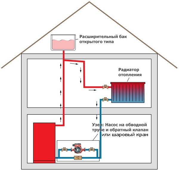
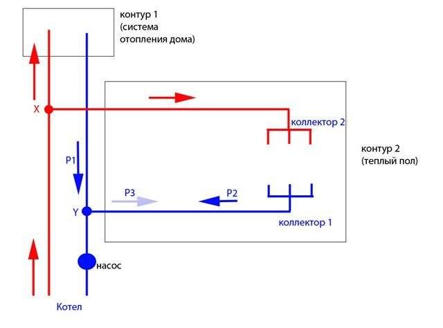
The use of shut-off valves is also mandatory in systems with a bypass. Such schemes are usually used when converting a scheme from gravitational fluid circulation to forced circulation.
In this case, the valve is placed on the bypass in parallel with the circulation pumping equipment. It is assumed that the main mode of operation will be forced. But when the pump is turned off due to a lack of electricity or a breakdown, the system will automatically switch to natural circulation.
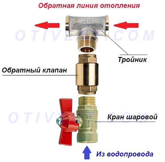
When arranging bypass units for heating circuits, the use of check valves is considered mandatory. The figure shows one of the possible options for connecting the bypass
This will happen as follows: the pump stops supplying the coolant, the check valve actuator stops under pressure and closes.
Then the convection movement of the liquid along the main line resumes. This process will continue until the pump starts. In addition, experts suggest installing a check valve on the make-up pipeline.This is optional, but highly desirable, as it avoids emptying the heating system for a variety of reasons.
For example, the owner opened a valve on the make-up pipeline to increase the pressure in the system. If, due to an unpleasant coincidence, the water supply is cut off at this moment, the coolant will simply squeeze out the remnants of cold water and go into the pipeline. As a result, the heating system will remain without liquid, the pressure in it will drop sharply and the boiler will stop.
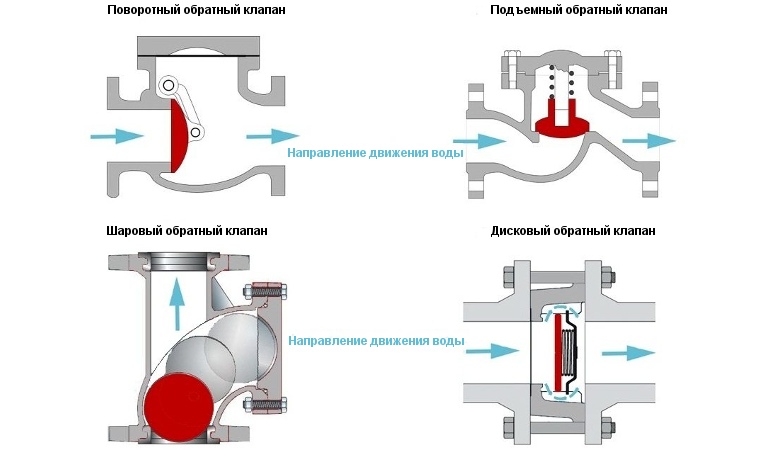
In the schemes described above, it is important to use the right valves. To cut off parasitic flows between adjacent circuits, it is advisable to install disk or petal devices
In this case, the hydraulic resistance will be less for the latter option, which must be taken into account when choosing.
In heating systems with natural circulation of the coolant, the use of spring check valves is impractical. Only paddle rotators can be installed here
For the arrangement of the bypass assembly, it is preferable to choose a ball valve. This is due to the fact that it gives almost zero resistance. A disc-type valve can be installed on the make-up pipeline. It should be a model designed for a fairly high working pressure.


Thus, the non-return valve may not be installed in all heating systems. It is necessarily used when arranging all types of bypasses for boilers and radiators, as well as at branching points of pipelines.
Balancing
Any CO requires hydraulic adjustment, in other words, balancing.It is carried out in various ways: with correctly selected pipe diameters, washers, with different flow sections, etc. balancing valve for heating system.
The purpose of this device is to supply the required volume of coolant and the amount of heat to each branch, circuit and radiator.

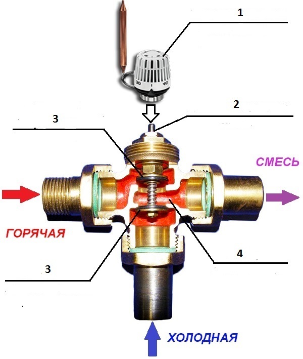
The valve is a conventional valve, but with two fittings installed in its brass body, which make it possible to connect measuring equipment (pressure gauges) or a capillary tube as part of an automatic pressure regulator.
The principle of operation of the balancing valve for the heating system is as follows: By turning the adjusting knob, it is necessary to achieve a strictly defined flow rate of the coolant. This is done by measuring the pressure at each fitting, after which, according to the diagram (usually attached by the manufacturer to the device), the number of turns of the adjusting knob is determined to achieve the desired water flow for each CO circuit. On circuits with up to 5 radiators, manual balancing regulators are installed. On branches with a large number of heating devices - automatic.
boiler part
The standard heating system includes many interesting components, where each of the elements performs a specific task. One of these components is a check valve that monitors the flow of coolant.
During operation, hydraulic pressure appears, which is unevenly distributed over all sections. This can occur due to various variations, but the most common causes of these problems are:
- Uneven cooling of the coolant.
- Construction errors.
- Incorrect system assembly.
The use of check valves in the boiler part occurs in most cases if two pits work in parallel. For example, in production they use one electric and any other. During operation, circuits are installed in parallel for a certain load at the supply or at the output, so that during the failure of one boiler, the second one continues to function.
This will allow you not to close the lines in a certain area. In addition, a sufficiently close location will allow normal shunting of pressure characteristics and heating the second boiler. Such valves are able to receive excess return through the heat exchanger and direct the output through the pipe.
If the boiler is solid fuel, then this will make the work of the radiator "shirt" very strong with heat removal. In the boiler part, it is enough to install valves at the inlets and outlets during parallel operation so as not to bother.