- Types of back-locking devices
- Making and installing a non-return valve with your own hands
- Necessary tools and materials
- Work progress
- Rules for installation and operation of the device
- Wiring diagram
- Types of heating systems with gravity circulation
- Closed system with gravity circulation
- Open system with gravity circulation
- Single pipe system with self-circulation
- Two-pipe system with self-circulation
- Ball check valve
- PVC check valve
- For pressure sewer
- Heating with forced circuit
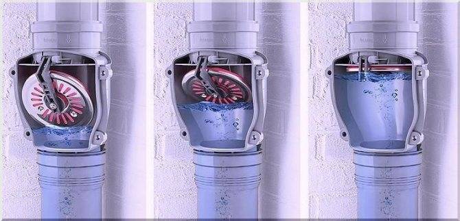
- Principle of operation
- 1 Varieties of check valves
- Peripheral secondary
- Device and principle of operation
- Frame
- locking organ
- Spring
- Seal
- What are the valves
- Gravity valves
- lifting
- Bivalves
- Installation subtleties
- Location selection
- Wrong Mounting Points
- Reinforcement installation procedure
- Why is a check valve needed?
- Conclusions and useful video on the topic
Types of back-locking devices
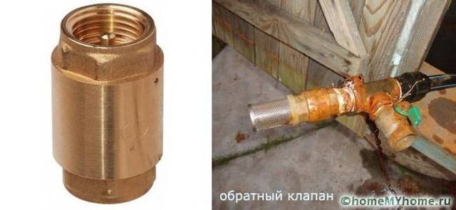
At the installation site, all check valves designed for pumping equipment are divided into two categories:
- for mounting on the suction pipe of a surface pump or through an adapter to a submersible pump;
- for pipeline installation.
The former prevent the reverse movement of water and ensure that the system is constantly filled, the latter regulate the pressure in the water supply.
We recommend installing both types of check valves, as the functions of the devices are different. The valve on the suction hose additionally protects the pump from "dry running", prevents the occurrence of air pockets, that is, it is responsible for the health of the pump. Even if the equipment is initially equipped with the option of protection against "dry running", thanks to the check valve, you will not have to constantly fill in water.
 Installing such a valve at the suction point is a must. But to stabilize the pressure in the system, a similar device is mounted in front of the pumping station or in front of the hydraulic tank, if it is located separately
Valves that are installed on the pipe in the house wiring prevent the liquid from returning to the outside - to the pump or well. They maintain the required water pressure and regulate the pressure. The main function of pipe models is considered to be the protection of pumping and plumbing equipment from sudden pressure surges and water hammer.
Making and installing a non-return valve with your own hands
Although the market offers a large selection of varieties of devices for solving various problems, some people decide to make their own valve. To do this, you will need to purchase individual elements of the future product and means of fastening.
Necessary tools and materials
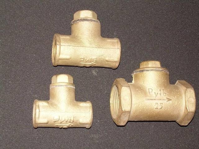
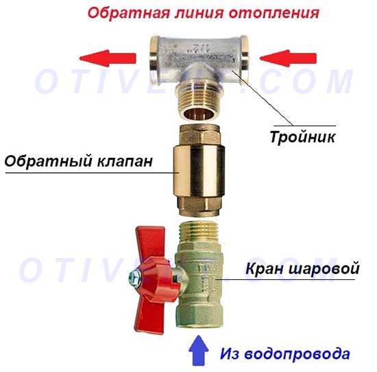
To independently make ball-type valves for water, you must prepare the necessary materials in advance:
- Tee with internal thread.
- For the valve seat, you need to take a coupling with an external thread.
- Stainless steel spring.It should fit freely into the hole.
- Cork. It will serve as a plug for the entire device and support for the spring.
- Steel ball, the diameter of which is slightly less than the nominal diameter of the tee.
- FUM tape.
Work progress
When all the materials are ready, you can begin the process of assembling the product. To do this, you can use the instructions below:
- First of all, a coupling is screwed into the tee, which will serve as a saddle for the gate element. It is necessary to screw in until the coupling closes the side hole of the tee by about 2 mm. This is necessary so that the ball does not jump out into the side passage.
- Through the opposite hole, first insert the ball, and then the spring.
- Spend a plug of the hole through which the spring was inserted. This is done with a screw plug using a sealing tape.
- Such a home-made device will allow water to pass into the side hole due to the fact that the direct flow will put pressure on the ball and on the spring, and in the absence of flow, the ball clogs the passage, returning to its original position under the action of the spring.
When making the device yourself, it is recommended to properly adjust the spring. It should not deviate when the pressure in the system is low, and not be too tight so as not to interfere with the normal flow of fluid.
Rules for installation and operation of the device
There are a number of rules and recommendations that must be followed during installation work:
- With the help of a valve, turn off the water supply completely or only at the installation site.
- Devices in which the working element comes to the closed position due to gravity should be mounted in a horizontal position.On vertical lines, such devices will only work if the water moves through the pipeline from the bottom up. All other types of valves can be mounted on both horizontal and vertical pipes.
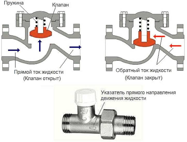
- The arrow on the body of the device must match the direction of water movement.
- It is recommended to install a strainer in front of the device, which will trap debris present in the liquid.
- In order to be able to diagnose the condition of the device in the future, a pressure gauge can be fixed at the outlet of the device.
- It is not recommended to destroy the paintwork on the instrument case, as it performs a protective function.
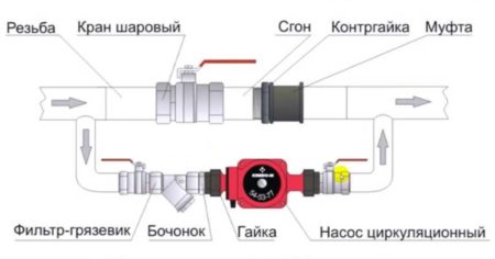
Wiring diagram
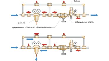
In heating and water supply systems, the choice of the location of the valve is determined by those areas where the flow of water or coolant is required in only one direction, and the hydraulic features of the system can lead to fluid flow in the opposite direction. These shut-off valves should be installed in accordance with all requirements of regulatory documents. There are the following connection schemes:
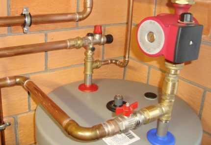
- If there are several pumps in the system installed in parallel to each other, then the valve should be mounted on the connecting pipe of each pump. This is done so that the water does not flow in the opposite direction through the failed pump.
- If heat flow sensors or water consumption meters are installed in the system, then a valve should be installed on their nozzles. The absence of a shutter can cause water to flow backward through the meters, which will lead to incorrect operation of these devices and incorrect readings.
- In heating systems with a common heat supply center, the device must be installed in the mixing units on the jumper. If this is not done, then the coolant can go from the supply pipe to the return pipe, bypassing the heating system.
- In the heating system, the valve is installed in the section through which the coolant flows from the heating device to the heating device, if there is a possibility of a pressure drop in this area. This will help prevent the backflow of water from the pipeline when the pressure drops in the external network. In this case, on the return section, it is necessary to install a pressure reducer operating on the principle of "to itself".
Connection diagram.
Types of heating systems with gravity circulation
Despite the simple design of a water heating system with self-circulation of the coolant, there are at least four popular installation schemes. The choice of wiring type depends on the characteristics of the building itself and the expected performance.
To determine which scheme will work, in each individual case it is required to perform a hydraulic calculation of the system, take into account the characteristics of the heating unit, calculate the pipe diameter, etc. You may need the help of a professional when doing the calculations.
Closed system with gravity circulation
In the EU countries, closed systems are the most popular among other solutions. In the Russian Federation, the scheme has not yet been widely used. The principles of operation of a closed-type water heating system with pumpless circulation are as follows:
- When heated, the coolant expands, water is displaced from the heating circuit.
- Under pressure, the liquid enters a closed membrane expansion tank.The design of the container is a cavity divided by a membrane into two parts. One half of the tank is filled with gas (most models use nitrogen). The second part remains empty for filling with coolant.
- When the liquid is heated, pressure is created sufficient to push through the membrane and compress the nitrogen. After cooling, the reverse process occurs, and the gas squeezes the water out of the tank.
Otherwise, closed-type systems work like other natural circulation heating schemes. As disadvantages, one can single out the dependence on the volume of the expansion tank. For rooms with a large heated area, you will need to install a capacious container, which is not always advisable.
Open system with gravity circulation
The open type heating system differs from the previous type only in the design of the expansion tank. This scheme was most often used in old buildings. The advantages of an open system is the possibility of self-manufacturing containers from improvised materials. The tank usually has modest dimensions and is installed on the roof or under the ceiling of the living room.
The main disadvantage of open structures is the ingress of air into pipes and heating radiators, which leads to increased corrosion and rapid failure of heating elements. Airing the system is also a frequent "guest" in open circuits. Therefore, radiators are installed at an angle, Mayevsky cranes are required to bleed air.
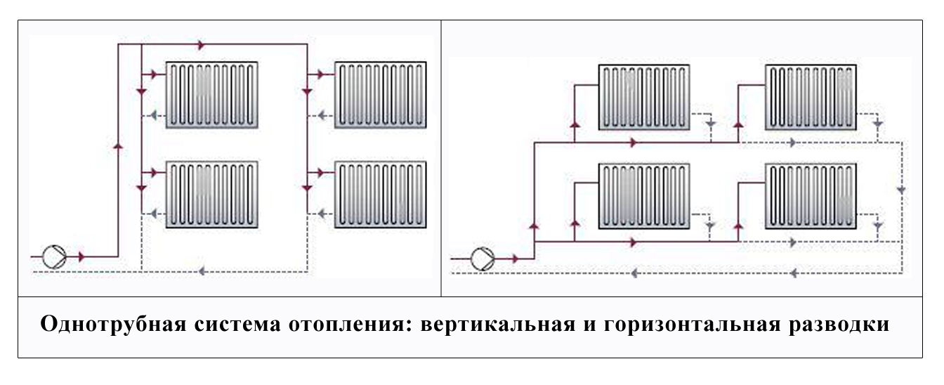
Single pipe system with self-circulation
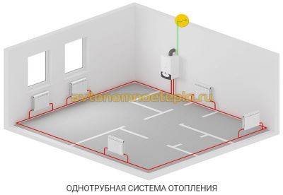
This solution has several advantages:
- There is no paired pipeline under the ceiling and above the floor level.
- Save money on system installation.
The disadvantages of such a solution are obvious. The heat output of heating radiators and the intensity of their heating decreases with distance from the boiler. As practice shows, a single-pipe heating system of a two-story house with natural circulation, even if all slopes are observed and the correct pipe diameter is selected, is often redone (by installing pumping equipment).


Two-pipe system with self-circulation
The two-pipe heating system in a private house with natural circulation has the following design features:
- Supply and return flow through separate pipes.
- The supply pipeline is connected to each radiator via an inlet.
- The battery is connected to the return line with the second eyeliner.
As a result, a two-pipe radiator type system provides the following advantages:
- Uniform distribution of heat.
- No need to add radiator sections for better warm-up.
- Easier to adjust the system.
- The diameter of the water circuit is at least one size smaller than in single-pipe schemes.
- Lack of strict rules for installing a two-pipe system. Small deviations regarding slopes are allowed.
The main advantage of a two-pipe heating system with lower and upper wiring is the simplicity and at the same time the efficiency of the design, which allows you to level errors made in the calculations or during installation work.
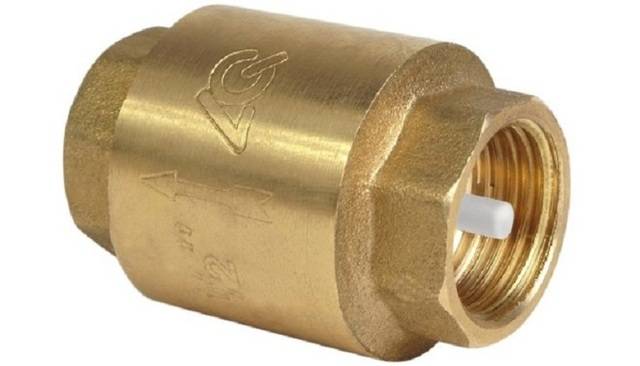
Ball check valve
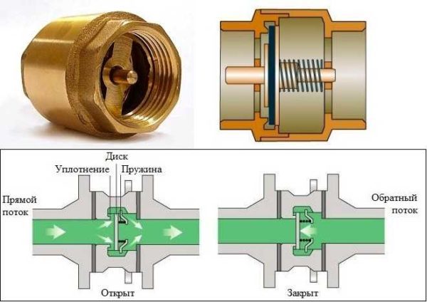
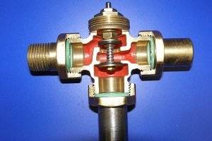
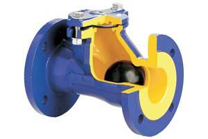 The most common type of check valve is the ball valve. It prevents the flow of wastewater in the opposite direction.The device of such a valve is simple, it looks like this: the shutter device here is a metal ball, which is pressed by a spring when back pressure appears.
Where to install a ball valve depends on its design. For example, a sleeve check valve is standardly installed in a vertical pipeline, and a flanged check valve is installed in both a vertical and a horizontal sewer pipeline.
A sleeve valve is installed if a check valve is installed on small diameter pipes (up to 2.5 inches). With a pipe diameter of 40-600 mm, a flanged check valve is installed.
A ball valve with a moving ball closes the return flows by 100%. It also has 100% forward passability. It is impossible to jam such a system. The standard non-return valve is made in a rugged body, with a massive cast iron cap, and the ball itself is coated with nitrile, EPDM, etc.
Another positive quality of the ball valve is its excellent maintainability.
If the ball needs to be cleaned or replaced, the sewer ball valve can be easily and quickly disassembled by simply removing 2 or 4 bolts on the valve cover.
PVC check valve
The non-return valve is very useful for owners of apartments on the lower floors. It can be installed on both internal and external sewers. This shut-off valve serves to block the return flow of sewage water and well delays the ingress of various insects and rodents through the sewer system.
If an emergency occurs and a backflow occurs, the valve will automatically shut off the entire sewer system. In such a valve, it is possible to block the return flow forcibly.To do this, simply turn the valve knob to the OFF position.
A shut-off element is built into the PVC sewer check valve, which moves back and forth, and perpendicular to the movement of wastewater in the sewer system. PVC lift check valve can be spring and springless.
Almost all check valves are designed so that they can be installed in both vertical and horizontal pipelines.
When doing this, the direction of wastewater flow must be taken into account - usually the direction is indicated by an arrow on the valve body. Non-return PVC valve does not react to ultraviolet radiation, does not give in to corrosion, does not react with aggressive chemical impurities
The duration of its operation corresponds to this indicator for plastic pipes
The PVC check valve does not react to ultraviolet radiation, does not corrode, does not react with aggressive chemical impurities. The duration of its operation corresponds to this indicator for plastic pipes.
If you properly operate the PVC check valve, then it is quite capable of lasting 50 years or more.
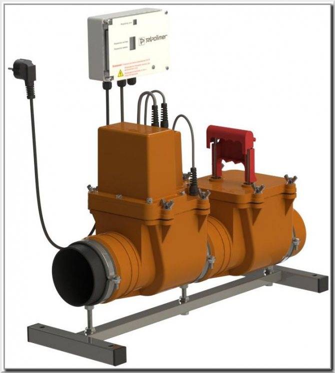
For pressure sewer
The non-return valve, which is installed in the pressure sewerage system, does not allow a change in the direction of the wastewater flow in the sewerage system. This safety valve only allows effluent to flow in one direction and stops the liquid from flowing in the opposite direction.
The check valve for pressure sewage works in automatic mode, and is called a direct-acting valve.This is an uninterrupted universal device, since the check valve can work both in normal mode and in an emergency.
For example, if several pumps are operating, and their pressure lines are combined into one common line, then one check valve (or several) is installed on each individual line, which protects each line from the pressure of the operating pump on any of them.
Thus, if the pressure drops on one line, then the pressure on the other lines will remain the same, and no accident will occur.
If the wastewater does not pass through the shut-off valve, then the check valve works like this: under the influence of its weight, the spool in the valve allows the movement of water through the valve seat. In order for wastewater to change direction, it must be suspended.


When the liquid flow stops, the pressure on the other side presses the spool, not allowing the backflow of sewage to form.
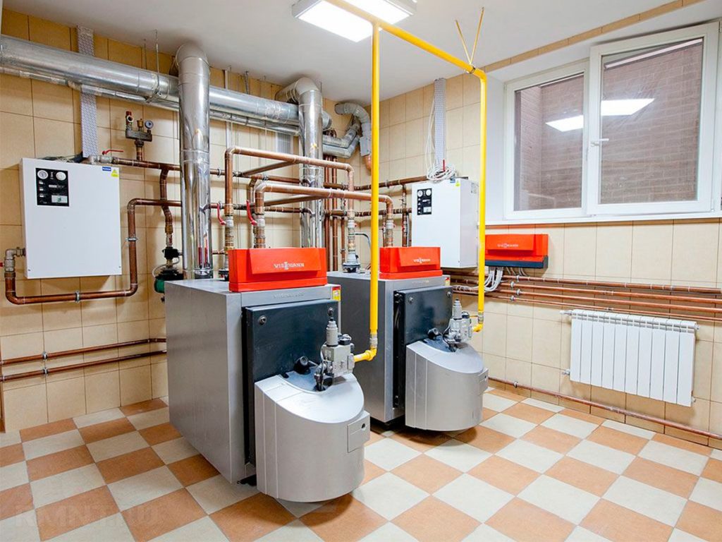
Heating with forced circuit
The forced circulation scheme includes equipment - a pump or a pump that increases the speed of fluid in the pipeline without increasing pressure.
Advantages:
 Forced heating circuit
- Possibility of heating large rooms. If the house has more than one floor, only forced circulation can be used.
- The system can be made more complex. The pump accelerates the movement of water, you can increase the number of turns.
- It is possible to use pipes of smaller diameter. The heating efficiency is not reduced, the structures look neater.
- For heating, the presence of air in the system is less critical. If air enters the network with natural circulation, it is possible to completely stop the movement of the coolant.You will need to install expansion tanks with air release systems.
- You can use lighter and cheaper plastic or polypropylene pipes.
- The pipeline can be hidden under the ceiling.
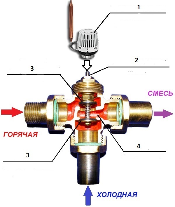
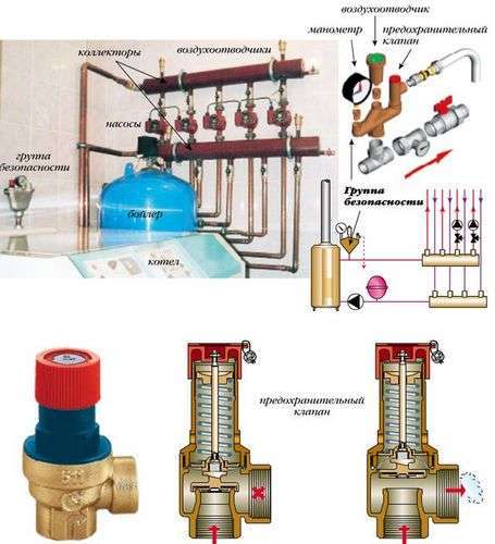
Principle of operation

The principle of its operation is based on the uniqueness of the design created by experienced engineers, which at the same time has nothing superfluous from a technological point of view. The case is presented in the form of a steel or cast iron product, inside of which one of the locking mechanisms is located, which functions with the help of a nearby spring (pressure exerted by it).
Thus, it is possible to open or close the valve in the desired direction in the direction of movement of the carrier. The hardness index is adjusted manually, depending on the requirements of the system. In the process of moving the working flow through the pipeline, the pressure indicator will increase, and this indicator will also affect the installed locking mechanism.
Based on the initial mechanical settings, the spring will be set to a certain value. If the specified mark is exceeded, the valve will begin to open, thereby allowing the carrier to move in a given direction. If the flow begins to weaken, then the spring will be rapidly pressed, thereby blocking the path of the working medium. The volume of liquid that has managed to penetrate will move in a given direction, but it will not be able to go back. The installed locking element will contribute to this.
1 Varieties of check valves
Any shut-off element (check valve, or its outdated name "non-return") has the main function - not to let the coolant into one pipe or branch pipe, and to pass it into the second. For various heating schemes, such an element is not always mandatory, so you need to proceed from the specific situation.
Three types of devices can be used for heating a private house:
- poppet;
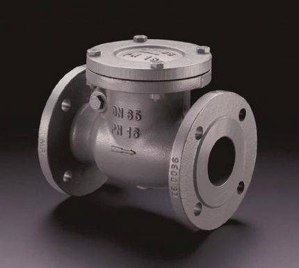
- flap check valve;
- ball.
In order to understand which heating system to install a certain type of valve, you need to study the main design features of each of them.
Peripheral secondary
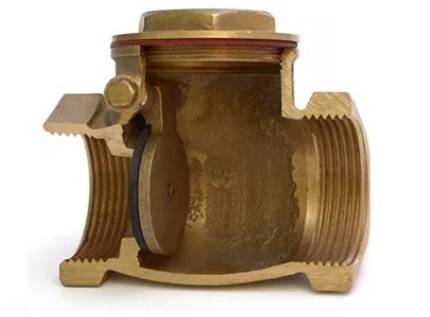
Check valve - an element of the heating system, consisting of a plastic or metal base, which performs the function of completely shutting off the coolant supply. This happens when the flow begins to move in the opposite direction. The metal disk is fastened to a spring, which is under pressure when the flow moves in one direction, and when the flow moves in the opposite direction, the spring works to block the passage in the pipe. The valve device has not only a disc and a spring, but also a sealing gasket. This component helps keep the drive in place tightly. Because of this, there is practically no possibility of pipe leakage. Butterfly valves are widely used in domestic heating systems.
Consider the principle of operation and an example of when check valves are necessary and when not. In the operating mode of circuits where circulation is present, the presence of a valve is optional. For example, if you look at a classic boiler room, where there are three parallel circuits. This can be a radiator circuit with a pump, a floor heating circuit with its own pump, and a boiler loading circuit.Often such schemes are used in work with floor boilers, which are called pump priority schemes.
Pump priorities are the definition of alternating pump operation. For example, the use of check valves occurs when only one pump remains in operation.
The installation of valves is completely eliminated if there is a hydraulic arrow on the diagram. This allows, during pressure drops in certain pumps, to get rid of this problem without the use of check valves. The hydraulic arrow indicates the closing section, which works to restore pressure in one of the pumps.
The presence of a floor-standing boiler in the circuit also allows you not to install check valves for heating. This happens due to its barrel, which bridges a certain place from the drop, which is considered to be zero resistance or a hydraulic arrow. The capacity of such barrels sometimes reaches 50 liters.
Check valves in heating are used if the boiler is placed at a sufficiently large distance from the pumps. Also, if the nodes and the boiler are at a distance of 5 meters, but the pipes are too narrow, this creates losses. In this case, a non-working pump can create circulation and pressure on other components, so it is worth putting a check valve on all three circuits.
Another example of using check valves is when there is a wall-mounted boiler, and in parallel with it, two nodes work. Most often, wall-mounted boilers have one radiator system, and the second is a mixing wall module, along with a warm floor. Check valves do not need to be installed, if the mixing unit operates only in a constant mode, then in the idle state, the valves will have nothing to regulate, because this circuit will be closed.
There are times when the pump does not work on the mixing wall unit. This sometimes happens when the room thermostat pump turns off during a certain room temperature. In this case a valve is needed because the circulation will continue in the node.
Now the market offers modern mixing units, when all the loops on the collector are turned off. In order for the pump not to idle, a bypass with a bypass valve is also added to the manifold. They also use a power switch that turns off the pump when all the loops on the collector are closed. The lack of proper elements can provoke a short-circuited node.


These are all cases where check valves are not needed. In most other conditions check valves are not required. Valves are used only in a couple of cases:
- When there are three parallel connection nodes and one of them is missing work.
- When installing modern collectors.
Cases where check valves are used are very rare, so now they are gradually being removed from use.
Device and principle of operation
Before choosing automatic cut-off devices, you should find out in more detail what they are, how they differ from each other, what materials they are made of. A product of any type consists of almost the same set of basic elements.

Frame
It can be made of corrosion-resistant materials: brass, stainless steel, cast iron or polypropylene. An arrow is applied to the surface indicating the direction of movement of the medium, the pressure for which it is calculated, in megapascals (MPa), and the diameter in inches or millimeters.
locking organ
It can be in the form of a ball, disk, plate.In some models, the locking body is made in the form of valves, like a disk cut in half. Above the cut line and parallel to it, an axis is mounted on which the leaf springs are put on.
Spring
Holds the locking element in the "closed" position in the absence of pressure. When the pump is turned on, the locking element compresses the spring and opens the passage, moving to the “open” position.
Seal
The valve seat is sealed with a polymeric material, ensuring its tight fit and tightness, and in the “closed” position. The most commonly chosen material for sealing is PTFE, in other words, fluoroplastic.
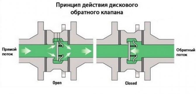
Despite some differences, products of all types have a common principle of operation:
- water enters the apparatus and presses on the shut-off organ;
- the spring pressing the shut-off body to the seat is compressed;
- the locking body, moving after the compressing spring, breaks away from the seat, freeing the passage in the right direction;
- when the water pressure decreases, the spring unclenches and presses on the shut-off organ, pressing it against the saddle, closing the passage.
Thus, any possibility of changing the direction of water movement in the pipeline is excluded.
What are the valves
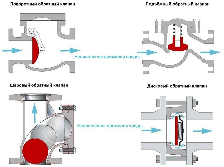
Taking into account the design features, the following types of devices are distinguished:
- lifting;
- petal;
- bivalve;
- gravitational.
It makes sense to get to know each of them better.
Gravity valves
Most devices can be attributed to spring. The exception is gravity valves, the mechanism of which does without springs. Their shut-off organ also opens with the pressure of water. In the absence of pressure, it returns to its place under the influence of its own weight (gravity). Their design is extremely simple.The disk of the locking body is suspended with one edge on an axis fixed in the body. Under water pressure, the disc turns on its axis and rises with its free edge up, opening the way for water. In the absence of impact, the disk under its own weight returns to the saddle, closing the passage for water.
Gravity valves include a reed valve (pictured below) and a rarely used ball valve. In the first case, the origin of the name can be explained by the similarity of the locking organ with the petal. In the second, the passage of water closes and opens a hollow ball made of light corrosion-resistant materials.
lifting
The locking mechanism of such devices is a metal disk sliding on a plastic rod passed through a hole in its center. The ends of the rod pass through the holes of the spool plates, preventing its axial displacement. A spring is installed between the shut-off body and one of the spool plates. When water is supplied to the inlet of the device, the shutter disk rises, compressing the spring. Hence its name - lifting.
Bivalves
The locking body in such devices consists of two halves of the disk, mounted on a steel axis, on which, moreover, springs are put on to hold the flaps in the “closed” position. By water pressure, the doors open to let water through.
Interesting! In the "open" position, the sashes resemble wings. Hence its popular name - butterfly.

Installation subtleties
Installing a sewer check valve is not a tricky business, plus such work does not require expensive tools, just a home kit, a drill, a hacksaw, a level, a tape measure, etc.But first you need to decide where to put the check valve.
Location selection
In this case, it all depends on where the system is most often clogged.
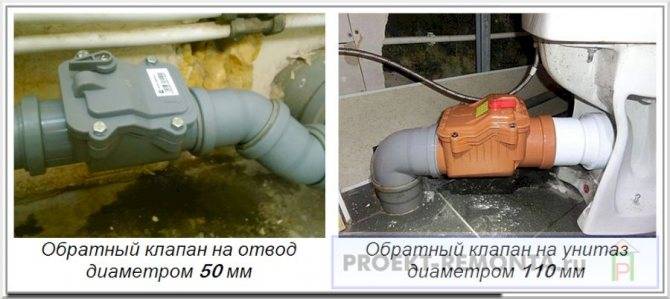
If blockages usually occur in the first sewer well from the house, then a 110 mm check valve is placed after the swivel elbow in the basement (before the pipe enters the wall).
When installed in multi-family buildings, the electric check valve of the sewerage system may require approval.
- The sewer valve in the apartment is best placed on a tee or crosspiece near the central drain into the riser.
- If there is no space near the riser for centralized fittings, then you will have to install a separate 50 mm sewer check valve for a drain towards the bathroom, kitchen, etc. And a shutter with a diameter of 100 - 110 mm on the toilet.
Check valve PVC or polypropylene, is considered the best solution for an apartment or a private house
Wrong Mounting Points
There are 2 recommendations here
- Before you install a check valve on the sewer, think about how you will service it, because every six months such fittings need to be audited.
- In a multi-storey building, it is unnecessary to put a vertical check valve on the riser.
About vertical fittings should be said separately, installing such a shutter, you can incur a lot of problems.
- If the riser is cast iron, then you can’t touch it at all, especially with your own hands, not every master undertakes to repair or replace the cast iron riser. This is due to the fact that there is a danger of the collapse of the entire column.
- Whatever the vertical check valve, it will interfere with the movement of drains, respectively, sooner or later a blockage will occur at this point.
- If drains rise from below and the valve blocks them, then in a multi-storey building, they will continue to drain from above, which will make the installation of the shutter useless.
- The sewer riser in an apartment building is a common structure. If you, on your own initiative, install a valve on it, then if problems arise with this fitting, you will be obliged to dismantle everything and return it to its original position for your money, plus pay overhead costs, for example, cleaning the basement or repairing neighbors who were flooded after installation valve.
A vertical check valve in apartment buildings should not be installed
Reinforcement installation procedure
Installing a check valve for sewage with your own hands is easy. The instruction consists of several simple steps, which I tried to reflect below in the photo and video in this article.


So, it is better for a simple home craftsman to buy a horizontal check valve with a manual blocking function, made of PVC or polypropylene. The pipe diameter does not affect the installation instructions, the check valve 50, 100 and 110 mm is installed in the same way
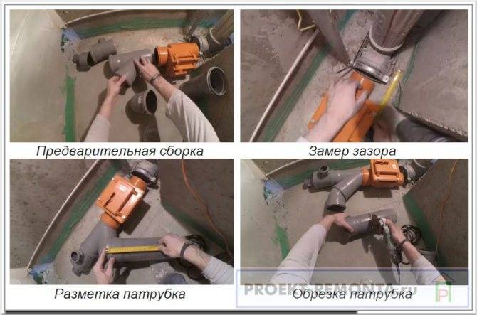
- First of all, just collect everything as it should be.
- Next, measure the distance from the valve to the outlet into the riser.
- Take a connecting adapter pipe of a suitable diameter and set aside the desired length on it, cut off the excess.
- After trimming, the edges of the pipe must be cleaned with a burr knife.
Reducer Fitting Diagram
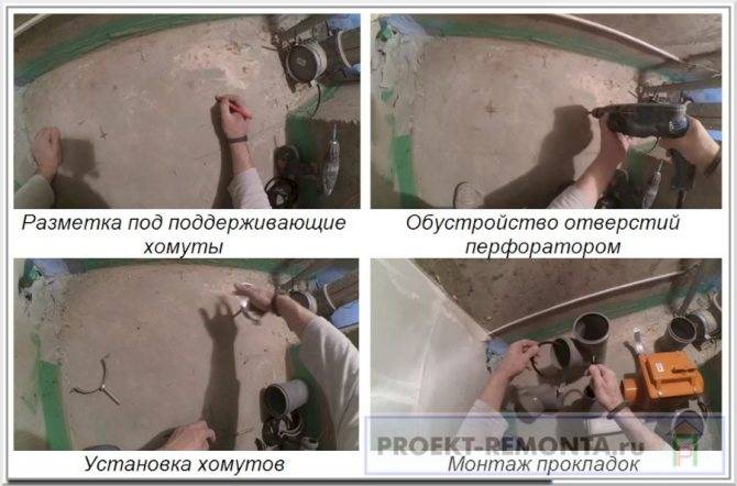
- Now find the central axis of the drain pipe and mark 2 points on it, on which the stop valves will be fixed.
- Drill 2 holes with a puncher and insert plastic dowels into them under the clamp studs.
- Pick up the studs in height and screw in the supporting clamps.
- Then you insert rubber gaskets into all the grooves and thickly coat all the joints with sealants, after which the stop valves are finally assembled.
Installation of supporting metal clamps
Now you just have to connect the system to the sewer drain and firmly fix it on metal clamps.
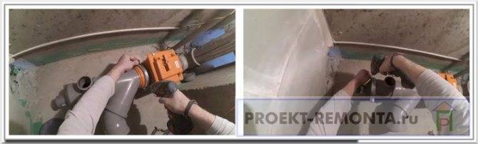
Fixing valves on clamps
Depending on the type of walls and the dimensions of the reinforcement, the system can be attached in three ways, the photo below shows the principle of fixation.
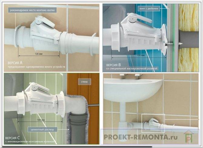
Three types of reinforcement fixation
Why is a check valve needed?
During operation, hydraulic pressure appears inside the heating system, which may not be the same in its various sections. The reasons for this phenomenon are very different.
Most often, this is uneven cooling of the coolant, errors in the design and assembly of the system, or its breakthrough. The result is always the same: the direction of the main fluid flow changes and it turns in the opposite direction.
This is fraught with very serious consequences up to the failure of the boiler, and even the entire system, which will require significant repair costs in the future.
For this reason, experts strongly recommend installing a check valve. The device is capable of passing fluid in only one direction. When a reverse flow occurs, the locking mechanism is activated, and the hole becomes impassable for the coolant.
Thus, the device is able to control the flow of liquid, passing it in only one direction.
The principle of operation of the check valve is very simple. It allows the heat transfer fluid to pass in a given direction and blocks the path when it tries to move in the opposite direction.
For normal operation of the system, it is necessary that the device does not create additional pressure, and freely passes the coolant moving towards the radiators
Therefore, it is extremely important to choose the right product
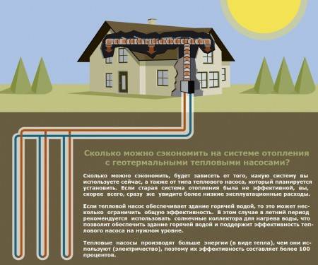
Conclusions and useful video on the topic
Where to use check valves:


How to choose the right shut-off valves for a gravity heating system:
How to equip heating make-up with a check valve:
The non-return valve is a necessary element of complex heating systems. For schemes with a single circuit, it is usually not needed, except for the arrangement of the make-up pipeline. However, if the system is complicated by the connection of a second boiler, boiler or underfloor heating, the device cannot be dispensed with.
It is very important to correctly select and install a check valve. This guarantees trouble-free long-term operation of the entire heating system.