- GOST with requirements for designations of welds
- Spot welding symbols in GOST drawings
- Rules for accepting spot welding
- Documents for accepting a welder for spot welding
- Conclusion
- Types of seams and their interpretation
- STRUCTURAL ELEMENTS OF WELDED JOINTS IN MANUAL ARC WELDING
- Creation of drawings using CAD
- Legend Examples
- Example #1
- Example #2
- Example #3
- Example #4
- Example #5
- Rules for applying designations and features of their decoding
- Example 1
- Example 2
- Example 3
- Example 4
- Example 5
- Square No. 5, seam dimensions
- What it is?
- Technological features of welding
- SYMBOLS FOR WELDED JOINTS
- Devil 5-10
- Shape and length
- Symbolic image of welds in the drawings in accordance with GOST 2.312-72 "Conditional images and designations of welded joints"
- What is a weld joint
- Kinds
- The need for welding markings
GOST with requirements for designations of welds
The assembly of a structure using welding joints is regulated by the following types of technical documentation:
- technological instruction;
- project for the production of welding works (PPSR);
- separate sections of the general project for the production of works (PPR).
An example of designation according to GOST.
The main purpose of the listed documents is to ensure a uniform reading and understanding of drawings and flow charts by engineers, workers and representatives of regulatory services.
At assessment of the quality of welded works documentation used:
- executive drawings with changes made by the manufacturer or installer of structures;
- approval by the developer or design organization of the changes made;
- certificates for welded materials.
Operational control is carried out by the contractor, the foreman for compliance of the work results with the requirements specified in the technological maps, approved instructions and state standards.
Spot welding symbols in GOST drawings
Reading a drawing is one of the main skills of a welder, its correct execution is a guarantee of the safety of many people, therefore the symbol must also be competent and accurate. Resistance welding in GOST drawings is indicated by certain signs, directions, extension lines and, if necessary, supplemented by a description. The main designations in the drawing:
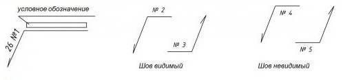
- Types of seam are indicated by a line:
- visible - solid;
- invisible - dotted;
- multilayer - contours indicating the number (number of seams). In addition, a remote arrow indicates exactly where the welding is to be carried out.
- The type of welded joint is indicated by alphabetic characters, each of which is supplemented with data, depending on the specifics.
GOST spot welding designation
| Type of welded corner | Letter designation | Additional required information |
| Butt | "FROM" | seam type + welding type |
| Angular | "U" | seam type + corner leg + seam point + welding type |
| Taurova | "E" | seam type + corner leg + welding type |
| overlap | "N" | St. dot diameter; roller welding width |
Rules for accepting spot welding
The standards define, without fail, the rules for acceptance of spot welding of metals and parts. Quality is determined after testing samples for several types of damage:
- gap;
- twisting;
- stretching;
- blow;
- compression.
In addition, the standards impose requirements on the technical conditions for the work, the compliance of materials in accordance with GOST, and the mandatory designation of resistance welding on the drawing according to which the work is carried out. In GOSTs, tolerances for various types of work are determined, with an exact indication as a percentage.
Documents for accepting a welder for spot welding
Welding is a very responsible job, on which the safety of people depends.
To carry out spot welding work, the welder must have the necessary package of documents:
- Welder's certificate - at least 2-5 years from the last certification (see by education);
- Electrical safety certificate, starting from group 2 and above for at least 1 year (see according to the latest certification);
- Certificate of passing fire safety - at least 1-3 years from the last certification (see by category).
In addition, the welder must:
- Professionally read the designation of spot welding on the GOST drawing;
- Pass introductory and periodic checks on knowledge of safety at a particular workplace;
- Know the procedure for issuing work permits for certain types of work;
- Know the types of work corresponding to the categories and qualifications of the welder.
Conclusion
Spot welding belongs to the most common - thermomechanical type of metal processing and is used in critical parts, structures, complex assemblies and assemblies.In the process of work, a large number of nuances, deviations from the given norm and unforeseen situations arise.
Welding, except for welding by automatic machines, is very dependent on the human factor, therefore, the welder performing these types of work has high requirements for knowledge, skills and responsibility.
This is so important that a unified register of welders in Russia, NAKS, has been created. Last names and data on education, certification are entered there.
This is another addition to general education, and with the help of an electronic catalog, it is much easier to find a job.
Types of seams and their interpretation
The designation of the weld in the drawing and their interpretation depends on the type of connection. The main connection methods include:
- Butt seam. It is characterized by end docking of parts. If necessary, you can pre-prepare the edges. In the drawings, it is denoted by the letter "C".
- Lap seam. This type implies parallel joining of elements with partial approach to each other relative to the welding plane. Has the designation "N".
- Tee seam. In this case, the end part of the second workpiece is welded to the plane of one part at a certain angle. In the technical documentation it is marked as "T".
The vast majority of parts are connected at an angle of 90º - this provides the necessary strength.
- Angular. As the name implies, the parts are welded at an angle of 90º, with or without preliminary preparation of the edges. Indicated by the letter "U".
- End. This method connects elements with a coaxial arrangement. In this case, the end part is a zone of surfacing of filler material.
Surfacing can be carried out only on one side. In this case, the seam is called one-sided.Bilateral connection means welding from two sides.


STRUCTURAL ELEMENTS OF WELDED JOINTS IN MANUAL ARC WELDING
In connection with the importance of the correct preparation of the edges to be welded in terms of quality, economy, strength and performance of the welded joint, state standards have been created for the preparation of edges for welding. The standards regulate the shape and structural elements of cutting and assembling edges for welding and the dimensions of finished welds.
GOST 5264-80 “Seams of welded joints. Manual arc welding. Basic types, structural elements and dimensions” and GOST 11534-75 “Manual arc welding. Connections are welded at acute and obtuse angles. Basic types, structural elements and dimensions” regulate the structural elements of edge preparation and the dimensions of the welds made in manual arc welding with a metal electrode in all spatial positions.
It is necessary to note some features of the application of standards. Various methods of electric fusion welding, due to their technological features, make it possible to obtain different maximum penetration depths. By varying the main parameters of the welding mode, constructive types of edge preparation, it is possible to increase or decrease the penetration depth and other dimensions of the weld.
For this reason, the mentioned standards, which regulate the structural elements of the groove, take into account the possibility of varying the strength of the welding current, voltage, diameter of the electrode wire (current density) and welding speed.In cases where the welding process provides the use of high currents, high current density and heat concentration, an increased amount of dullness, smaller groove angles and gap sizes are possible.
In manual arc welding, factors such as the amount of welding current, welding speed and arc voltage change within a small range.
To ensure through penetration of the edges of the product when welding one-sided butt or fillet welds with a sheet thickness of more than 4 mm, welding has to be carried out along pre-cut edges. In manual welding, welders cannot significantly change the depth of penetration of the base metal, but by changing the range of transverse oscillations of the electrode, they can significantly change the width of the weld.
With a sheet thickness of 9 - 100 mm, GOST 5264-80 for butt joints provides for mandatory cutting of edges and a gap, which have a different value depending on the thickness of the metal and the type of joint.
In all cases, using edge preparation standards, one should choose such types of grooves that provide the least volume and cost of edge preparation, the volume and mass of deposited metal, full penetration in thickness, a smooth shape of the interface of the outer part of the weld and minimal angular deformations.
The quality of welded joints and the efficiency of the welding process are greatly influenced by the cleanliness of the edges and the surface of the base metal adjacent to them, the accuracy of edge preparation and assembly for welding. Blanks for welded parts should be made of pre-straightened and cleaned metal.Cutting out parts and preparing edges is carried out by mechanical processing (on press shears, edge-cutting and milling machines), oxy-fuel and plasma cutting, etc. After using thermal cutting methods, the edges are cleaned from burr, scale, etc. (grinding wheels, metal brushes and etc.).
In some cases, when welding high-alloy steels, the base metal in the heat-affected zone after cutting is also removed mechanically. Before assembling the edge, adjacent areas of the base metal (40 mm from the edge) must be cleaned of oil, rust and other contaminants with metal brushes, shot blasting or chemical pickling. Parts are assembled on tacks (short seams) 20–30 mm long or in special assembly devices.
Creation of drawings using CAD
Almost all drawings, according to which various metal structures are subsequently manufactured using welding technologies, are performed using special software (CAD). Automation of the process of creating technical schemes allows developers to significantly save time on the preparation of project documentation.
Thanks to CAD, designers quickly and with maximum accuracy apply all welding seams on the drawings, their designation is also carried out by appropriate software systems that are able not only to model the most complex metal products, but almost instantly carry out the most complex calculations of welding joints due to the selection of ready-made engineering solutions in specialized built-in libraries.
Currently, designers are offered a large number of different products, of which the following software systems are the most effective and in demand:
- Kompas;
- AutoCAD;
- solidworks.
For example, in a matter of seconds, Compass finds any necessary welding drawings, and their interpretation is immediately displayed on the monitor without the need to waste time searching for additional sources.
Undoubtedly, a professional designer must be able to manually carry out technical diagrams and, moreover, know how welding is indicated on the drawing. But at the same time, work productivity will be much higher if specialized programs are used in the process of paperwork.
With the help of software systems, it is possible to develop not only units and assemblies of welded structures, but also to calculate the maximum allowable loads during their operation. In turn, this allows specialists, even at the stage of project development, to apply the right decisions regarding the design features of metal products, while excluding the formation of inaccuracies due to inaccurate selection of welding technologies and, in particular, types of connecting joints.
All modern automated programs offered to design engineers are developed with maximum compliance with the requirements established by technical regulations and legal documents.
The ability to use the designation of welded joints in the drawings and in particular to create diagrams in an automated mode using CAD allows you to correctly and accurately draw up documentation and ensure the conditions for the successful manufacture of metal products through welding.
Legend Examples
To make it clearer for you, and you can quickly understand all the notation, we will give some simple and illustrative examples. So, let's begin.
Example #1
In the picture above, you see a butt weld, in which one edge has a curved bevel. The connection itself is double-sided, made by manual arc welding. There is no reinforcement on either side. On the front side, the weld roughness is Rz 20 µm, and on the reverse side, Rz 80 µm.
Example #2
Here you can see that the seam is angled and double-sided, it has no bevels or edges. This connection is made by automatic welding and using flux.
Example #3
Here we again have a butt seam, but without bevels or edges. The connection is one-sided, with a lining. A seam was made using heated gas and welding wire.
Example #4
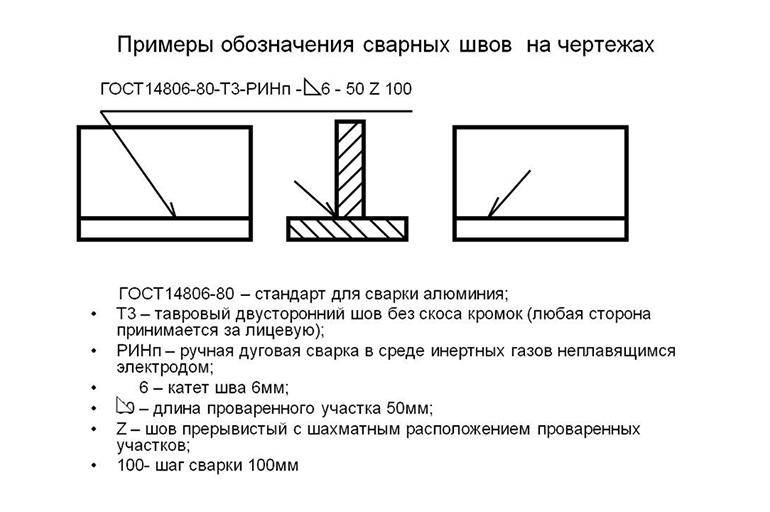
In the fourth example, the seam is tee, has no bevels or edges. It is discontinuous and performed bilaterally. The seam is like a checkerboard pattern. The work was carried out with the help of RDS in a gas medium and using a non-consumable metal rod. The leg of the seam is 6 millimeters, and the length of the seam is 50 millimeters, in increments of 100 millimeters (indicated by the letter "Z"). t w is the length of the seam, and t pr is the length of the step of the intermittent connection.
Example #5
In our last example, the seam is overlapped, has no bevels and edges. It is also single-sided and is performed by manual gas-shielded arc welding using a consumable rod. The welded joint is made along an open line. The leg of the seam is 5 millimeters.
Rules for applying designations and features of their decoding
It has already been mentioned above how the designation of welded joints of different types should be carried out.A line with a directed arrow indicates the line of the joint, above or below which inscriptions are applied.


There are certain rules according to which all technical inscriptions must be applied. Weld marking consists of 9 interconnected between blocks. The photo below shows the structure of the markings.
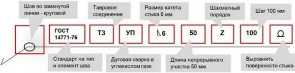
The photo shows how the welded joint is indicated in the drawing using the example of a double-sided assembly butt weld performed by manual arc welding:
- The first column shows an auxiliary sign. This is the contour of a closed seam, which determines the installation conditions put forward to the element.
- The second block contains the code of the interstate standard, in accordance with which the work on welding the metal structure should be carried out.
- The third column is the marking (designation) of the weld in the drawing.
- Next, a hyphen is shown, which separates all subsequent positions on the subcategory.
- The letters in the fifth block indicate the technology by which welding is performed. This position is not mandatory.
- The sixth column contains the value of the angular leg, its value is indicated in millimeters.
- Seventh block: additional designation - intermittent weld, pitch interval, chain or staggered arrangement, etc.
- The eighth block displays auxiliary signs indicating the type of processing.
- The last ninth column is the surface cleanliness of the butt joint. Indicated in cases where after the welding process, mechanical processing of the product is necessary.
This is the standard designation of welds in the drawings, examples of the designation of some already completed connections are given below.
Example 1
The weld symbol shown in the drawing is deciphered as follows:
- the sign indicates that directly at the installation site, after fitting the elements, they should be connected;
- GOST 5264-80 is the number of the regulatory document, in this case it indicates that the joint was made using electric arc welding;
- C13 - means that in the butt joint on one bevel there is a curved chamfer;
- the sign indicates that internal thermal stress (force) has been removed from both sides of the seam;
- Rz20 is an indicator of the cleanliness of the surface of the front side, Rz80 is the indicator of the reverse side.
Example 2
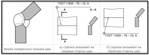
Shown here is a two-sided (U2) fillet weld without beveled edges, made by automatic arc welding (A) along a closed line under a flux (GOST 11533-75).
Example 3
A joint is created on the back side.
The connection is made using electric arc welding in accordance with GOST 5264-80. The seam is one-sided with a bend of the edge, the contour is open.
Example 4
Welding connection at an angle
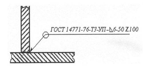
- the contour of the joining of the elements is solid, made in the form of a ring;
- welding was carried out in a gaseous environment, GOST 17771-76;
- tee joint (TZ), each side of it was processed without cutting edges;
- carbon monoxide (CO) of a gaseous consistency was used as a gaseous medium, the electrode was meltable;
- 6 mm is the length of the leg of the butt joint;
- in a checkerboard pattern (Z), a continuous welded area 50 mm long and with a step of 100 millimeters is periodically created.
Example 5
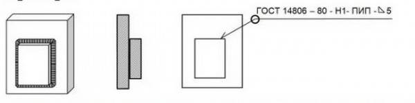
To make the seam, semi-automatic arc welding was used, the drawing indicates that the seam is one-sided (H1), created by a consumable overlap electrode without beveled edges in a shielding gas environment. The seam is circular (), made along a closed line, 5 mm (Δ5) is the length of the leg.
If the drawing contains several identical connecting joints, then only one of them is marked with a symbol. For the rest of the seams in the places where there should be a designation, only their serial numbers are indicated. In this case, the number of identical connections is indicated on the leader line, as shown in the example below.
The same butt joints are considered in cases where:
- the types of joints and the dimensions of the elements are the same when comparing their cross section;
- the same requirements apply to all connections.
When the category of its control or the control complex is set for the welding joint, then only under the leader line, a symbol should be applied.
Square No. 5, seam dimensions
These are the required seam dimensions. It is most convenient to indicate the length of the leg, since we are talking about a T-shaped version with a perpendicular union at a right angle. The leg is determined depending on the yield strength.
Classification of welds.
Additional connections are:
- SS unilateral, for which the arc or electrode moves on one side.
- BS double-sided, the source of melting moves on both sides.
The third participant of our drawing and welding party - GOST 2.312-72, just dedicated to images and symbols, enters into business.
According to this standard, the seams are divided into:
- Visible, which are depicted as a solid line.
- Invisible, indicated in the drawings by a dotted line.
Now back to our original seam. We are able to translate this welding symbol into a simple and understandable text for the human ear:
Double-sided tee seam by manual arc welding in protective carbon dioxide with edges without bevels, intermittent with a staggered arrangement, the leg of the seam is 6 mm, the length of the welded area is 50 mm, the step is 100 mm, the bulges of the seam should be removed after welding.
What it is?
The executive scheme is an integral element of the design and working documentation for water supply, heat supply, transport pipelines and technological installations with liquid or gaseous media. It is performed out of scale and gives only a general idea of the relative position of welds in space. The drawing is necessarily tied to geodetic coordinates or to an object with known coordinates.


When forming a document, the order of the seams in a particular section of the pipeline is observed. The document is a guide to the implementation of welding work, a means of planning and control. It is issued together with a summary table of joints, which summarizes the data on the joints in tabular form. In addition to the technical parameters of the welds, the personal data of the welders and the number of their personal brand are given.
Technological features of welding
Any work has its secrets, which are mostly owned by professionals and welding is no exception. For example, when making a tee joint consisting of sheets of different thicknesses, the electrode holder should be set in such a way that the angle between it and the thick sheet is 60 degrees.
Another feature of the T-type implementation is the installation of sheets in the "boat", that is, the angle between the workpiece and the horizontal plane should be 45 degrees. With this form of installation of workpieces, the electrode can be installed strictly vertically. As a result, the welding speed increases and the probability of such defects as undercut decreases, by the way, this is the most common defect in the T-weld. Depending on the thickness of the metal, it may be necessary to make several passes with the electrode. Welding in the "boat" is used when using automatic welding.
SYMBOLS FOR WELDED JOINTS
2.1. Auxiliary signs for designating welds are given in the table.
| Auxiliary sign | The meaning of the auxiliary sign | The location of the auxiliary sign relative to the shelf of the leader line drawn from the image of the seam | |
| from the front | on the reverse side | ||
| Remove seam reinforcement | |||
| Process sags and irregularities of the seam with a smooth transition to the base metal | |||
| The seam should be performed during the installation of the product, i.e. when installed according to the installation drawing at the place of use | |||
| Intermittent or spot seam with chain arrangement Line angle 60° | |||
| The seam is intermittent or dotted with a checkerboard pattern | |||
| Closed seam. Sign diameter — 3…5 mm | |||
| Seam along an open line. The sign is used if the location of the seam is clear from the drawing |
Notes:
1. For the front side of the one-sided seam of the welded joint, take the side from which welding is performed.
2. For the front side of the double-sided seam of the welded joint with asymmetrically prepared edges, take the side from which the main seam is welded.
3.Any side can be taken as the front side of a double-sided welded joint with symmetrically prepared edges. In the symbol of the seam, auxiliary signs are made in solid thin lines. Auxiliary signs must be the same height as the numbers included in the designation of the seam.
2.2. The structure of the symbol for a standard seam or a single spot weld is shown in the diagram (Fig. 5).
Devil 5-10
Damn.5
The sign is made with solid thin lines. The height of the sign must be the same as the height of the numbers included in the designation of the seam.
2.3. The structure of the symbol for a non-standard seam or a single weld spot is shown in the diagram (Fig. 6).
Damn.6
The technical requirements of the drawing or table of seams indicate the welding method by which a non-standard seam should be made.
2.4. The symbol for the seam is applied:


a) on the shelf of the leader line drawn from the image of the seam on the front side (Fig. 7a);
b) under the shelf of the leader line drawn from the image of the seam on the reverse side (Fig. 7b).
Damn.7
2.5. The designation of the roughness of the machined surface of the seam is applied on the shelf or under the shelf of the leader line after the symbol of the seam (Fig. 8), or indicated in the table of seams, or given in the technical requirements of the drawing, for example: "The surface roughness parameter of welds ...". Note. The content and dimensions of the columns of the table of seams are not regulated by this standard.
Damn.8
2.6. If a control complex or a category of control of the weld is established for the seam of the welded joint, then their designation may be placed under the leader line (Fig. 9).
Damn.9
In the technical requirements or the table of seams in the drawing, a link is given to the corresponding regulatory and technical document.
2.7. Welding materials are indicated on the drawing in the technical requirements or in the weld table. It is allowed not to specify welding materials.
2.8. If there are identical seams in the drawing, the designation is applied to one of the images, and leader lines with shelves are drawn from the images of the remaining identical seams. All identical seams are assigned one serial number, which is applied:
a) on the leader line, which has a shelf with a printed seam designation (Fig. 10a);
b) on the shelf of the leader line drawn from the image of the seam, which does not have a designation, on the front side (Fig. 10b);
c) under the shelf of the leader line drawn from the image of the seam, which does not have a designation, on the reverse side (Fig. 10in).
Damn.10
The number of identical seams is allowed to be indicated on the leader line, which has a shelf with an applied designation (see drawing 10a).
Note. Seams are considered the same if: their types and dimensions of structural elements in cross section are the same; they have the same technical requirements.
2.9. Examples of symbols for welded joints are given in Appendices 1 and 2.
This is interesting: Treatment of the weld after welding - thermal, mechanical, anti-corrosion
Shape and length
The shape of the seam can be convex, even (flat). Sometimes it becomes necessary to make a concave shape. Convex connections are designed for heavy loads.
The concave places of the alloys withstand dynamic loads well. Versatility is characterized by flat seams, which are made most often.
Along the length, the seams are continuous, having no intervals between the fused joints. Sometimes intermittent stitches are enough.
An interesting industrial variation of the intermittent weld is the joint that is formed by resistance seam welding. They do it on special equipment equipped with disk rotating electrodes.
Often they are called rollers, and this type of welding is called roller welding. Solid connections can also be made on such equipment. The resulting seam is very strong, absolutely tight. The method is used on an industrial scale for the manufacture of pipes, containers, hermetic modules.
Symbolic image of welds in the drawings in accordance with GOST 2.312-72 "Conditional images and designations of welded joints"
In accordance with the GOST 2.312-72 standard, for a conditional image of a weld, regardless of the welding method, two types of lines are used: solid if the weld is visible or dashed if the weld is invisible.
The seam line is indicated by a one-sided arrow.
The arrow can be made with a shelf to accommodate the seam symbol and, if necessary, auxiliary signs. The symbol is placed above the shelf if the arrow points to the front side of the weld (i.e. if it is visible), or below the shelf when the seam is located on the reverse side (i.e. if the seam is invisible). In this case, the side from which welding is performed is taken as the front side of the one-sided seam of the welded joint. For the front side of the double-sided seam of the welded joint with asymmetrically prepared edges, the side from which the main seam is welded is taken. Any side can be taken as the front side of a double-sided welded joint with symmetrically prepared edges.


Auxiliary signs.
| Auxiliary sign | Description | seam visible | The seam is invisible |
|---|---|---|---|
| The seam is to be performed during the installation of the product (mounting seam). | |||
| Closed seam. | |||
| Seam along an open line. | |||
| The seam is intermittent with a chain arrangement. | |||
| . | |||
| Remove the bulge of the seam. | |||
| Process sags and irregularities of the seam with a smooth transition to the base metal. |
The diagram below shows the structure of a standard weld symbol.
The alphanumeric designation of the seam according to the relevant standard is a combination consisting of a letter defining the type of welded joint and a number indicating the type of joint and seam, as well as the shape of the groove. For example: C1, T4, H3.
The following letters are used to designate welded joints:
- C - butt;
- U - angular;
- T - tee;
- H - overlap;
- O - special types, if the shape of the seam is not provided for by GOST.
Symbols for seams for some welding methods are presented in the table:
| Standard | Compound | Seam symbols |
|---|---|---|
| GOST 5264-80. Seams of welded joints, manual arc welding | Butt | C1 - C40 |
| Tavrovoe | T1 - T9 | |
| overlapping | H1 - H2 | |
| Angular | U1 - U10 | |
| GOST 14771-76. Seams of welded joints, welding in shielding gases | Butt | C1 - C27 |
| Tavrovoe | T1 - T10 | |
| overlapping | H1 - H4 | |
| Angular | U1 - U10 |
The designations of the welding method (A, G, UE and others) are indicated in the standard according to which the welding process indicated in the drawing is performed.
Symbols for some welding methods are presented below, for example:
- A - automatic submerged arc welding without the use of linings and pillows and a backing seam;
- Af - automatic submerged arc welding on a flux pad;
- IN - welding in inert gases with a tungsten electrode without filler metal;
- INp - welding in inert gases with a tungsten electrode, but with filler metal;
- IP - welding in inert gases with a consumable electrode;
- UP - welding in carbon dioxide consumable electrode.
What is a weld joint
The welding process is a technological operation for the formation of a monolithic joint. The area where the melting and solidification of the material of the joined parts took place is called the weld.
Kinds
The welded joint is subdivided:
Butt. The connection is formed along the end surfaces of the parts. It is carried out with processing of edges and without it. "C" marking.
Lap. The planes of the parts are parallel to each other and partially overlap one another. "H" marking.
Tavrovy. The end face of the part adjoins the plane of another part at an angle. The seam is located along the joint. "T" marking.
Angular. The main planes of the joined parts in the welding zone are located at an angle to each other. "U" marking.
End. The semi-finished product is pressed by the side surfaces. The seam is formed by fusing metal on the ends of the products.
The seam is performed:
Unilateral. Welding is carried out on one side of the connection (joint).
Bilateral. Processing takes place on both sides.
The need for welding markings
Any design consists of separate parts (assemblies) interconnected in one way or another. One of them is welding. The joint has its own characteristics that affect the performance of the product as a whole.
The designation of welding in the drawing is an explanation of the method of joining, the shape of the seam and its geometric parameters, the method of execution and other additional information. A competent engineer will gain additional information:
- about strength - the connection is continuous or intermittent; in addition, thermal stresses are formed in the weld zone;
- on the size and shape of the deposited metal;
- tightness of the joint;
- connection time - before installation or during its process, and more.
It's interesting: how cut the pipe by electric welding?


