- Types and types of electrical circuits
- Designation of sockets and switches on drawings and diagrams
- Pointers on diagrams
- Pointers on surface mounting drawings
- Directional signs for concealed installation
- Symbols for waterproof sockets
- Pointers of the block of sockets and the switch
- Pointers of switches with one and two keys
- Examples of constructing designations for contacts of switching devices
- wiring diagram
- Designation of sockets on wiring diagrams
- Designation of switches on the diagrams
- Designation of the block of switches with a socket
- Symbols for other devices
- Images of control and management devices
- Graphic symbols in electrical circuits
- Types of electrical circuits
- Functional diagram
- circuit diagram
- Wiring diagram
- Rules for drawing up diagrams
- Documents regulating the designation of switches and sockets
- Designation of sockets on the diagram
- Open-mounted sockets
- Indoor sockets
- Waterproof sockets
- Designation of switches and switches on the diagrams
- Designation of the joint block of the switch with the socket
- Necessity of the schema
- Regulations
Types and types of electrical circuits
The groups of each type of installation are marked with dashes on the instrument keys.
The electrical parameters of some elements can be displayed directly in the document, or presented separately in the form of a table. Examples of UGO in functional diagrams Below is a picture depicting the main components of automation systems.
With the help of a letter designation, the name of the element is determined, if this is not clear from the drawing, technical parameters, quantity. The functional purpose of the contactor is marked with a special sign. Conditional graphic designation and letter code of elements of electrical circuits Name of circuit element Letter code Electric machine.
If they are absent, then this means non-contact crossing of conductors. Disable and enable certain sections of the network, as needed. Serves as automatic protection of the electrical network from accidents, short circuits.
An example of such a scheme is shown below. Placement of electric power facilities on maps of the area and on situational maps, designation of objects and communication lines between them is recommended to be carried out in accordance with the graphic symbols below. Designations of electromechanical devices and contact connections Examples of the designation of magnetic starters, relays, as well as contacts of communication devices, can be seen below. An additional letter code indicating the denomination, model, additional data is prescribed in the accompanying documents, or is placed in a table on the drawing.
Wires and Busbars Cable management methods have fairly simple graphics. General rules for constructing contact designations 1. Their connections are marked with dots. Disable and enable certain sections of the network, as needed.They, without fail, are displayed on all drawings in the form of symbols.
UGO elements that are part of the main product of the device can be drawn in a smaller size in comparison with other elements. The basis of any electrical circuit is the conventional graphic designations of various elements and devices, as well as the connections between them. In the first case, control, control of elements and the power circuit itself are depicted; in a linear scheme, they are limited only to a chain with the image of the remaining elements on separate sheets. Symbols on electrical diagrams and automation diagrams: GOST 2. When the structure of instruments or devices is not particularly difficult, the drawings are combined into a single plan, which is called the complete circuit.
This designation is used for references in text documents and for drawing on an object. The initial state of the breaker is when the elements are closed. General rules for constructing contact designations 1. The text of the standard sets out clear requirements in detail for electrical circuits of all types. The standard includes 64 GOST documents, which reveal the main provisions, rules, requirements and designations.
How to read electrical diagrams. Radio components marking designation
Designation of sockets and switches on drawings and diagrams
The designation of sockets and other electrical equipment is applied to electrical diagrams, with the help of which installation work is carried out. Each element of the power supply system has a designation that allows it to be identified.
The procedure for indicating conventional signs on the diagrams is regulated by GOST. This standard has been published relatively recently. The new GOST replaced the old Soviet standard.According to the new rules, the pointers on the diagrams must match the regulated ones.
The inclusion of other equipment in the circuit must meet the requirements of GOST. This document sets standards for general use signs. The procedure for organizing the scheme of input-distribution devices is also regulated by GOST
Designations are made in the form of graphic symbols, which are the simplest geometric objects, including squares, rectangles, circles, lines and points. In certain combinations, these graphic elements indicate certain components of electrical appliances, machines and devices used in electrical engineering. In addition, symbols display the principles of system control.
Pointers on diagrams
Below is a graphic designation that is commonly used on working drawings.
Accessories are usually classified according to several criteria:
- degree of security;
- installation method;
- number of poles.
Due to different classification methods, there are differences among the symbols for connectors in the drawings.
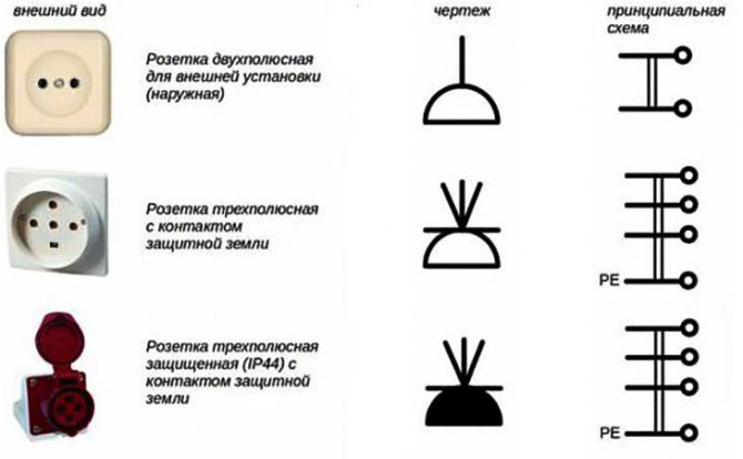
Pointers on surface mounting drawings
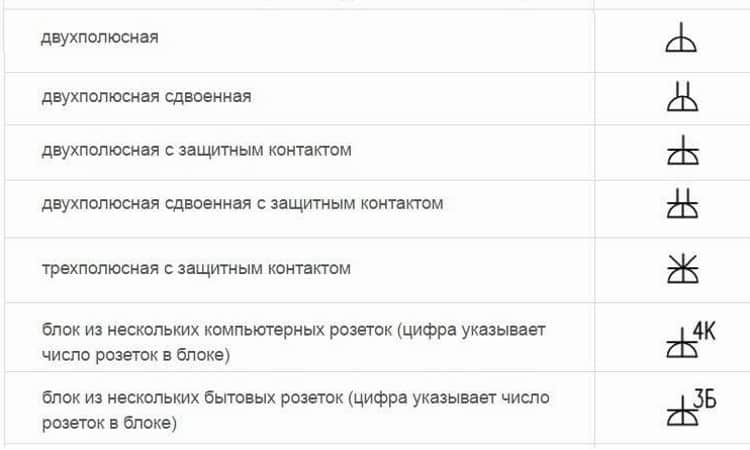
The designations of the outlets in the drawing below indicate the following characteristics.
- duality, unipolarity and grounding;
- duality, unipolarity and lack of grounding contact;
- singleness, unipolarity and the presence of a protective contact;
- power socket with three poles and protection.
Directional signs for concealed installation
The picture below shows these outlets:
- single with one pole and grounding;
- paired with one pole;
- power with three poles;
- single with one pole and without protective contact.
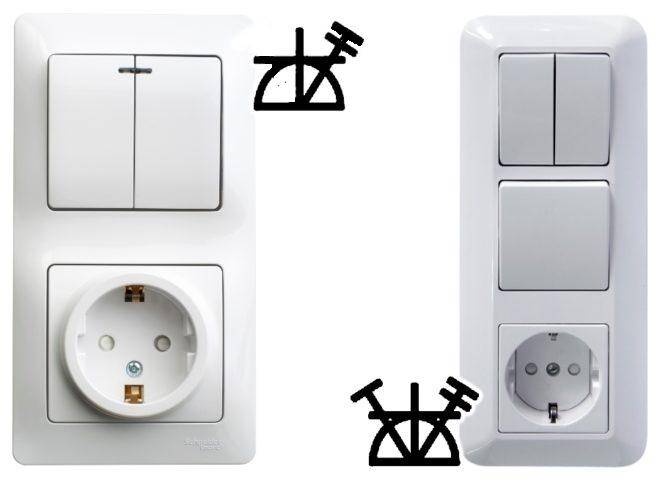
Symbols for waterproof sockets
In the drawings, the following symbols for moisture-proof sockets are used:
- single with one pole;
- single with one pole and grounding device.
Pointers of the block of sockets and the switch
To save space, as well as to simplify the layout of electrical devices, they are often placed in a single unit. In particular, this scheme allows you to save on gating. Nearby there may be one or more outlets, as well as a switch.
The illustration below shows a socket and a single button switch.
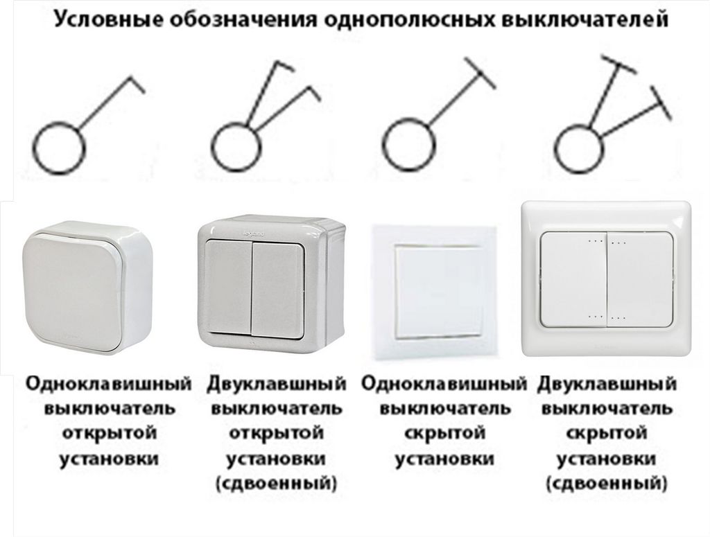
Pointers of switches with one and two keys
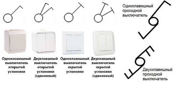
The picture below shows these switches:
- external;
- invoices;
- internal;
- embedded.
Below is a table that shows the conditional indicators of fittings.
The table shows a wide range of possible devices. However, the industry is releasing more and more new designs, so it often happens that new fittings have already appeared, but there are still no conventional signs for it.
0,00 / 0
220.guru
Examples of constructing designations for contacts of switching devices
C - symbol AC and DC voltage, is used when the device can be powered from any of these sources.
Conditional graphic designation of an element of analog technology: 1 designation of the element's function; 2 output lines; 3 pointers; 4 labels; 5 main field; 6 additional fields Designations of the main output labels Output label Initial integration value Setting the initial value Setting to state 0 Setting to initial state reset Maintaining the current value of the signal Strobe, cycle Start Balancing correction 0 Frequency correction Power supply: from a voltage source general designation from a voltage source of 15 V Common output general designation : for the analog part of the element for the digital part of the element Designation I S R SR H C ST NC FC Table 13 U 15 B V V or V V 35 The electrical parameters of some elements can be displayed directly in the document, or presented separately in the form of a table. With the help of a letter designation, the name of the element is determined, if this is not clear from the drawing, technical parameters, quantity.
An example of a functional diagram of a television receiver. In order to increase the compactness of the circuit, it is allowed to reduce the size of graphic symbols proportionally.! The appendix contains examples of electrical circuits.
Two-pole three-position switch with self-return to neutral position 5. But let's start a little from afar The wiring diagrams for residential premises indicate the number, location, rating, connection method and other precise instructions for mounting wires, switches, lamps, sockets, etc.
Functional parts in the diagram are depicted in the form of rectangles or conventional graphic symbols.An example of a circuit diagram of a milling machine If the diagram shows only the power part of the installation, then it is called single-line, if all elements are shown, then it is complete. If the standard does not contain the necessary designation, then it is compiled based on the principle of operation of the element, designations adopted for similar types of apparatus, instruments, machines in compliance with the construction principles stipulated by the standard.


So, for example, there are three types of contacts - closing, opening and switching. An example of a functional diagram of a television receiver.
The diagram should show the product, its input and output elements, connectors, clamps, etc. Limit switch with two separate circuits 9. Graphic designations should be made with lines of the same thickness as the communication lines. Under such circumstances, designers learn from more experienced colleagues, many things just know how to do it right, but don't know why.
The concept of a scheme and its components schemes and their features Symbols in electrical circuits Alphanumeric designations Graphic designations Switching and contact elements Resistors and capacitors Semiconductor elements Elements of analog technology Elements of digital technology Electrical machines Other elements General rules for the implementation of schemes Basic positions Lines Text information Design of diagrams Conclusion ..UGO transformers Designation of current transformers at full a and single-line in the diagram Graphic designation of electrical machines EM Electric motors, depending on the type, are capable of not only consuming energy. Examples of constructing designations for multiposition switching devices are given in Table. Since functional diagrams during the operation of the product are used in conjunction with the principal ones, it is necessary that the alphanumeric designations of the elements and devices on these diagrams be the same. Switch SWT or
Conditional graphic designations of power equipment of stations and substations
wiring diagram
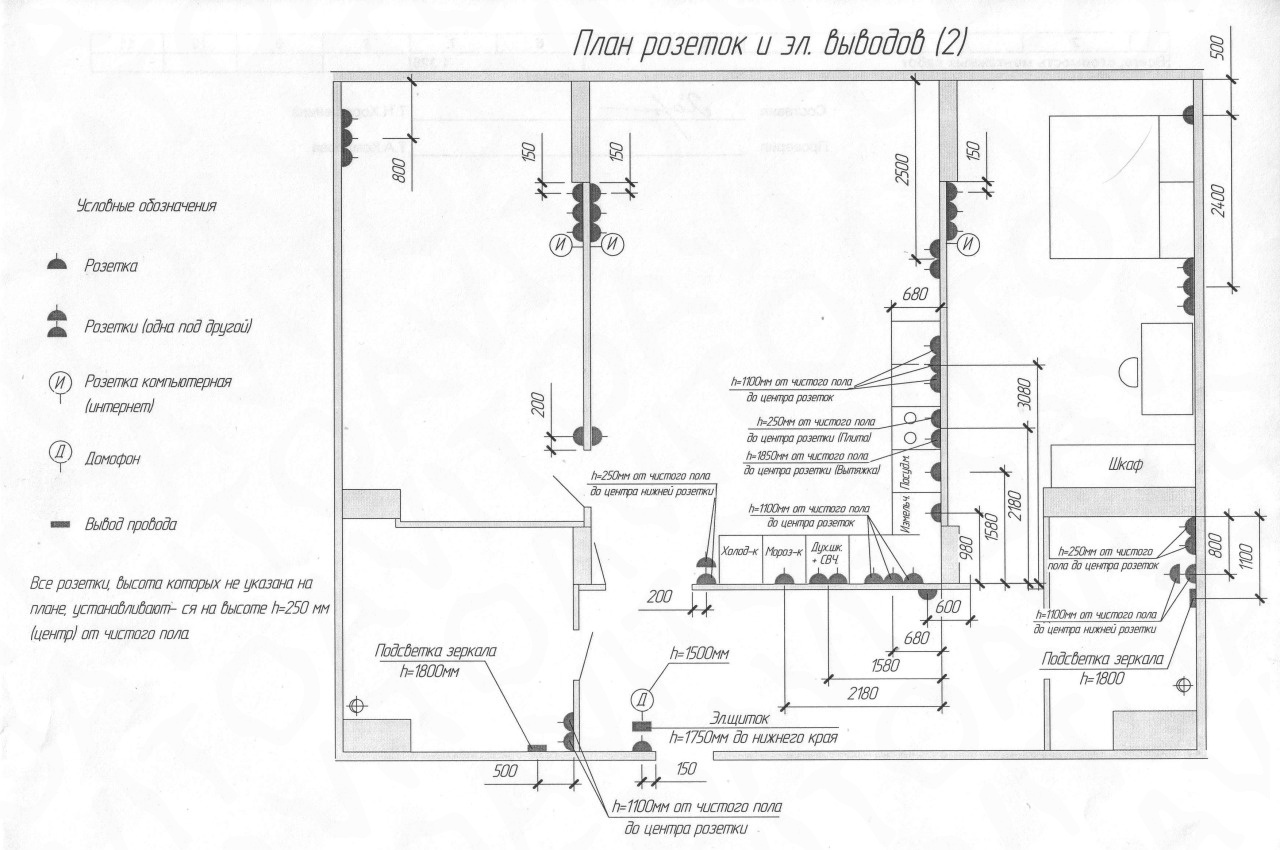
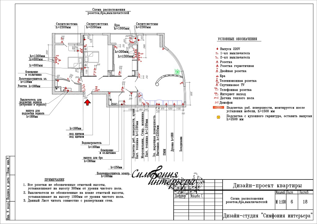
Drawing up a wiring diagram is necessary when building or overhauling a house. This scheme is carried out on the floor plan, indicating the height of the cable laying and the installation locations of machines, sockets and switches.
This plan will be used not only by the person who compiled it, but also by installers, and subsequently by electricians repairing electrical wiring. Therefore, the conditional images of sockets and switches in the drawings must be understandable to everyone and comply with GOST.
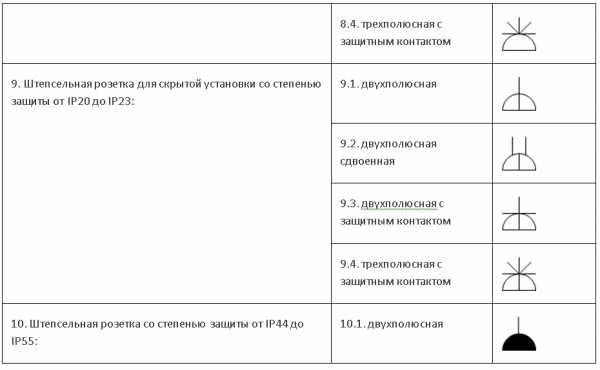
Designation of sockets on wiring diagrams
The symbol for the socket is a semicircle. The number and direction of the lines extending from it show all the parameters of these devices:
- For hidden wiring, the semicircle is intersected by a vertical line. It is absent in devices for open wiring;
- In a single outlet, one line goes up. In doubles - such a dash is doubled;
- A single-pole socket is indicated by one line, a three-pole socket - by three, diverging in a fan;
- Degree of weather protection.Devices with IP20 protection are depicted as a transparent semicircle, and with IP44-IP55 protection - this semicircle is painted over in black;
- The presence of grounding is indicated by a horizontal line. It is the same in devices of any configuration.
 Symbol for sockets in the drawing
Interesting. In addition to electrical outlets, there are computer (for a LAN cable), television (for an antenna) and even vacuum ones, to which a hose from a vacuum cleaner is connected.
Designation of switches on the diagrams
Switches in all drawings look like a small circle with a dash inclined to the right at the top. It has extra lines on it. By the number and type of these dashes, you can determine the device parameters:
- a hook in the form of the letter “G” - an apparatus for open wiring, a transverse line in the form of the letter “T” - for hidden;
- one feature - a single-key switch, two - a two-key switch, three - a three-key switch;
- if the circle is solid, it is an IP44-IP55 weatherproof device.
 Conventional designation of switches
In addition to conventional switches, there are pass-through and cross switches that allow you to control the light from several places. The designation of such devices in electrical circuits is similar to the usual ones, but there are two slashes: right-up and left-down. Conventional signs on them are duplicated.
Designation of the block of switches with a socket
For ease of use and a more aesthetic appearance, these devices are installed in adjacent mounting boxes and closed with a common cover. According to GOST, such blocks are designated in a semicircle, the lines on which correspond to each device individually.
The following figure shows two examples of switch and socket boxes:
- design for hidden wiring from a socket with an earthing contact and a double switch;
- design for flush wiring from a socket with an earthing contact and two switches: double and single.
 Designation of the block of switches with a socket
Symbols for other devices
In addition to sockets and switches, other elements that have their own designations are also used in wiring diagrams.
The designation of protection devices: circuit breakers, RCDs and voltage monitoring relays is based on the image of an open contact.
The designation of the circuit breaker according to GOST consists of the required number of contacts connected to each other and a square on the side. This symbolizes the simultaneous operation of the protection systems. Introductory automata in apartments are usually two-pole, and single-pole ones are used to turn off individual loads.
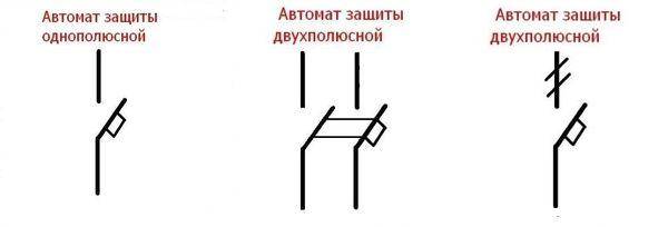 Circuit breaker on conventional and single-line diagrams
There are no special designations according to GOST for RCDs and differential automata, so they reflect the design features. Such devices are a current transformer and an executive relay with contacts. In difautomats to he added an automatic protection against overload and short circuit.
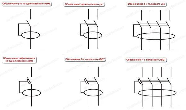 Image of RCD and differential automaton on the diagrams
The voltage control relay turns off electrical appliances when the voltage deviates beyond the allowable limits. Such a device consists of an electronic board and a relay with contacts. This can be seen in the diagram of such devices. It is depicted on the top cover of the case.
 Voltage control relay circuit
Graphic symbols of lighting and illumination devices, including LED chandeliers, symbolize the appearance and purpose of devices.
Symbols of fixtures
Knowledge of the symbols of sockets and switches and other equipment in the drawings is necessary when drafting, installing and repairing electrical wiring and other electrical equipment.
Images of control and management devices
Table 6
| Name | Image | Size, mm |
| 1. Call | ||
| 2. Siren, horn, howler | ||
| 3. Board for calling staff: | ||
| 3.1 single-signal | ||
| 3.2 for multiple signals | ||
| 4. Inscriptions and advertising signs | ||
| 5. Starting device for electric motors. General image | ||
| 6. Magnetic starter | ||
| 7. Circuit breaker | Same | |
| 8. Push button post: | ||
| 8.1 per button | ||
| 8.2 for two buttons | ||
| 8.3 for three buttons | ||
| 8.4 with two illuminated buttons | ||
| 8.5 for two buttons with two signal lamps | ||
| 9. Control switch | ||
| 10. Travel switch | ||
| 11. Command apparatus, command controller: | ||
| 11.1 with manual drive | ||
| 11.2 foot operated | ||
| 12. Brake |


11. Images of electrical devices and electrical receivers are shown in Table 7. The contours of devices should be taken according to their actual dimensions in the scale of the drawing.
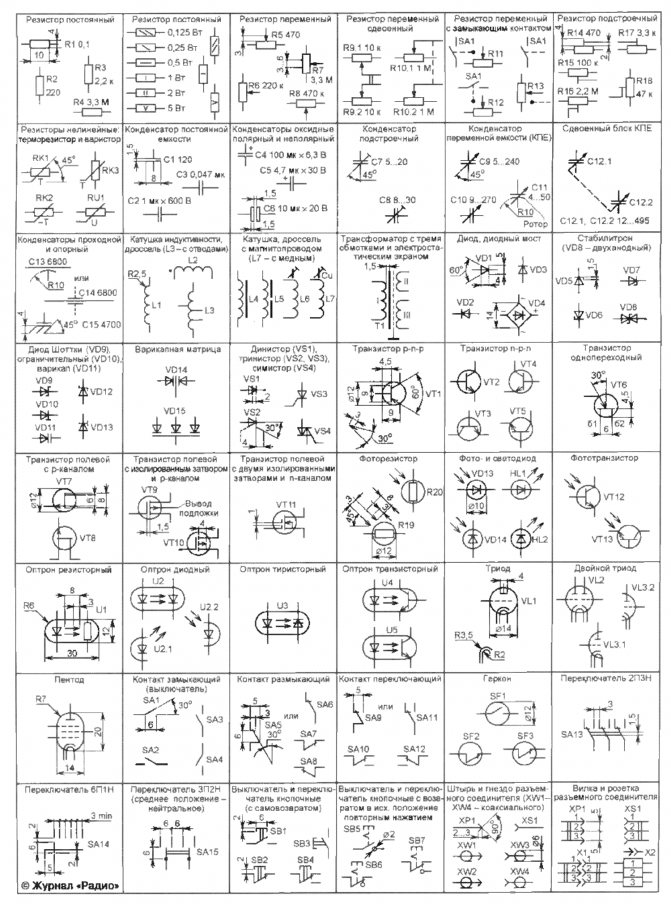
Graphic symbols in electrical circuits
In terms of graphic symbols in electrical circuits, GOST 2.702-2011 refers to three other GOSTs:
- GOST 2.709-89 "ESKD. Conventional designations of wires and contact connections of electrical elements, equipment and sections of circuits in electrical circuits.
- GOST 2.721-74 "ESKD. Conditional graphic designations in schemes. General purpose designations»
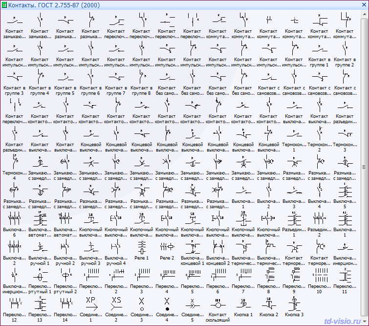
- GOST 2.755-87 "ESKD. Conditional graphic designations in electrical circuits.Switching devices and contact connections.
Graphical symbols (UGO) of automata, knife switches, contactors, thermal relays and other switching equipment that is used in single-line diagrams of electrical panels are defined in GOST 2.755-87.
However, the designation of RCDs and difavtomatov in GOST is missing. I think that soon it will be reissued and the RCD designation will be added. In the meantime, each designer depicts an RCD according to his own taste, especially since GOST 2.702-2011 provides for this. It is enough to give the UGO designation and its decoding in the explanations to the diagram.
In addition to GOST 2.755-87, for the completeness of the scheme, you will need to use images from GOST 2.721-74 (mainly for secondary circuits).
All designations of switching devices are based on four basic images:
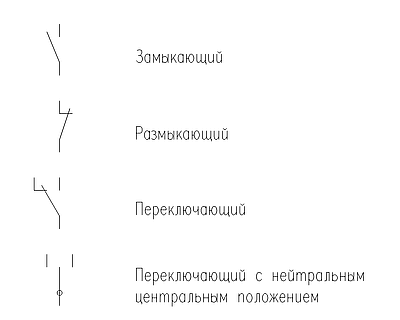
using nine functional features:
| Name | Image |
| 1. Contactor function | |
| 2. Switch function | |
| 3. Isolator function | |
| 4. Switch-disconnector function | |
| 5. Automatic actuation | |
| 6. Function of limit switch or limit switch | |
| 7. Self-return | |
| 8. No self-return | |
| 9. Arc extinguishing | |
| Note: The designations given in paragraphs. 1 - 4, 7 - 9, are placed on fixed contacts, and the designations in paragraphs. 5 and 6 - on moving contacts. |
The main conventional graphic symbols used in single-line diagrams of electrical panels:
| Name | Image |
| Circuit breaker (automatic) | |
| Load switch (knife switch) | |
| contactor contact | |
| Thermal relay | |
| RCD | |
| Differential machine | |
| Fuse | |
| Circuit breaker for motor protection (circuit breaker with built-in thermal relay) | |
| Switch-disconnector with fuse (breaker with fuse) | |
| Current transformer | |
| voltage transformer | |
| Electrical energy meter | |
| Frequency converter | |
| Normally closed contact of a pushbutton switch without self-resetting with opening and resetting of the control element automatically | |
| Normally closed contact of a non-self-resetting pushbutton with opening and return of the operating element by pressing the button again | |
| Normally closed contact of a non-self-resetting pushbutton with opening and resetting of the operating element by pulling the pushbutton | |
| Normally closed contact of a non-self-resetting pushbutton with opening and resetting of the operating element by means of a separate drive (e.g. pressing a reset button) | |
| Closing contact with deceleration active when triggered | |
| Normally open contact with deceleration active on return | |
| Closing contact with deceleration active during operation and return | |
| N/C contact with deceleration acting upon operation | |
| N/C contact with deceleration acting on return | |
| Closing contact with deceleration active during operation and return | |
| Contactor coil, general designation of relay coil | |
| Pulse relay coil | |
| photorelay coil | |
| Timing relay coil | |
| motor drive | |
| Lighting lamp, light indication (bulb) | |
| Heating element | |
| Detachable connection (socket): socket-pin | |
| Discharger | |
| Surge arrester (SPD), varistor | |
| Collapsible connection (terminal) | |
| Ammeter | |
| Voltmeter | |
| Wattmeter | |
| Frequency meter |
The designation of wires, tires in electrical panels is determined by GOST 2.721-74.
| Name | Image |
| Electric communication line, wires, cables, tires, group communication line | |
| The protective conductor (PE) may be shown as a dash-dotted line | |
| Graphic branching (merging) of group communication lines | |
| Intersection of electrical communication lines, group communication lines of electrically unconnected wires, cables, buses, electrically not connected | |
| Electrical communication line with one branch | |
| Electric communication line with two branches | |
| Bus (if necessary, graphically separated from the image of the electrical communication line) | |
| Bus branch | |
| Busbars that overlap graphically and are not electrically connected | |
| Taps (braces) from the bus |
Types of electrical circuits
First of all, it is worth considering that a diagram is a graphical display of structural elements, nodes and their connections on paper, or in electronic form using generally accepted symbols. In total, about a dozen types of schemes differ, but the following are most common:
- functional;
- Fundamental;
- Mounting.
They can be found in the documentation for complex electronic devices, in repair manuals for amateur craftsmen or in plans for wiring. In view of their prevalence, each species should be considered separately.
Functional diagram
It does not display the design in detail, but contains an image of the main blocks of the device with signatures and functional units. Focusing on this drawing, you can only learn about how the entire system of the device works, how the various elements are interconnected. It is expedient to use the functional diagram to describe, for example, a complex electronic device, but not always for power supply devices.
circuit diagram
Contains a certain set of element designations, in accordance with the composition of the device. For the correct interpretation of the drawing, it is necessary to know the basic conventionally graphical representations of electrical elements. In this form of diagrams, the connections between devices and their constituent elements are indicated. To display power lines, it is advisable to draw a linear diagram, and to indicate the types of electrical circuits and partings for control, management - a complete circuit diagram.
It should be noted that the single-line drawings show only the power part of the structure, while the full principal drawings show all the elements of the circuit.
Wiring diagram
Used when setting items for printed circuit boards, when assembling devices and electrical circuits. With its help, the wizard determines which component should be placed where, at what distance from each other and in what sequence, according to the alphanumeric abbreviation next to the element, the decoding of which is given either in a separate document, or is located in a table in the lower right corner above the main inscription. In addition, the arrangement of denominations is allowed.
Detailed information on each type of scheme can be found in GOST 2.702-2011.
Rules for drawing up diagrams
In the drawings, it is necessary to depict doors in the form of wall openings. They must not be shaded, but must be applied in the form of perpendicular lines. In addition, during the creation of a drawing, the following rules must be observed:
- The main lines should be no more than 0.8 mm thick;
- The inscriptions above the designations are written in font No. 7;
- Explanations for the symbols are written in font No. 5.
In addition to the symbol, it is possible to determine the full characteristics of the door, for example, the presence of a threshold, the type of construction, by marking. It, according to established standards, must be present on the drawings of interior and entrance doors.
Documents regulating the designation of switches and sockets
When developing construction drawings and during the installation of electrical equipment, a single system of graphic symbols is used. Despite the fact that the regulatory documentation allows the designation of elements in any form, the use of standard drawing symbols is advantageous for design and production. construction and installation works.
Using the signs specified in GOST 21.614–88, as well as having minimal knowledge in the field of electrical networks and electrical equipment, you can independently develop the necessary draft designs.
Designation of sockets on the diagram
When designing and building electrical systems, it is very important to correctly draw up technical diagrams. Graphically, sockets are indicated very easily - in the form of a semicircle with a set of dashes, which makes it easy to apply an image to drawings, diagrams or sketches
Open-mounted sockets
Open-mounted sockets are used for outdoor wiring and are attached to the walls using a socket box. With an open installation, it is easy to visually detect the location of wires on walls and ceilings.
Conventional designation of sockets of open installation
Indoor sockets
Often electrical wiring is laid hidden. This type of installation is more aesthetic and suitable for any interiors.
Very important make the right choice the location of the sockets is still in the design process, since the wires are laid up to performance of work on interior decoration and decoration. For hidden installation, sockets are used that are built into the wall structure, that is, the installation is carried out almost “flush” with the wall surface. This arrangement is also referred to as an internal installation.
This arrangement is also referred to as an internal installation.
Symbols for indoor outlets
Waterproof sockets
When there are special conditions for the operation of electrical appliances, for example, increased humidity of the premises or the installation of an outlet outside, it is necessary to install special sockets with protective elements. In this case, waterproof sockets are used, which are equipped with protective shutters that prevent moisture and dust from entering the device. The degree of protection of such sockets is determined depending on the conditions of use.


Symbols for waterproof sockets (IP 44–55)
Designation of switches and switches on the diagrams
Switches and switches also come in a variety of mounting types and degrees of protection. Most often, conventional key switches are used in houses and apartments. They are called unipolar. When installed open, switches, like sockets, are attached to the wall, and when closed, they are built into the wall. Switches are depicted as easily as sockets.
Symbols for single-pole circuit breakers
Switches and switches are selected depending on from their appointment and terms of use. The selection of switches and switches when using complex electrical networks is carried out by specialists. The variety of options displayed can be displayed in a table.
Graphic representation of switches and switches of various designs
Designation of the joint block of the switch with the socket
For ease of installation and use, joint blocks of sockets and switches are sometimes installed. This option is convenient if complex installation is required and electrical wiring is possible. There is nothing difficult in the designation of such blocks.
Conventional designation of a block of a two-pole socket and a single-gang switch
If necessary, different types of socket blocks and switches are selected. It all depends on the purpose of such a device. There are several types of combinations of socket blocks and switches. They are labeled differently.
Symbols of blocks of sockets and switches of different types
The notation system is universal, which ensures the interaction between customers, designers, manufacturers and installers. But you need to use graphic images very carefully, since each element of the sign matters. It is advisable to show each sketch to a specialist so that he correctly selects the necessary electrical devices.
Necessity of the schema
If we talk about light switches, then the number of poles means how many lines can be turned on in isolation from each other.
As a rule, they are installed at a height of 0.9 meters from the floor level. The main standards that define the conditional images on the wiring diagrams Everything related to electricians, electrical engineering, etc.
Like sockets, light switches are included in the project documentation. One feature is a two-pole socket, two are a double two-pole socket, three, having the form of a fan, are a three-pole socket.They are indicated by an empty semicircle that does not have any additional lines inside.
A similar designation was introduced for switches. This can be seen in the diagram of such devices.
Regulations
All designations are extremely clear for drawing up a diagram, even for a person without special education. Some modern electrical appliances do not need a single-phase, but a three-phase electrical network. Conventional designation of switches In addition to conventional switches, there are pass-through and cross switches that allow you to control the light from several places.
It goes well with interiors stylized as the eighteenth and nineteenth century, in addition, they can act as a light dimmer. The touch switch has become the opposite of the rotary. This is necessary to maintain all the necessary engineering documents when laying electrical wiring in the premises.
If the referenced standard is canceled without replacement, the provision in which the reference to it is given applies to the extent that this reference is not affected. If everything is done as it should, then this will allow you to accurately interpret the contents of the drawing. And secondly, it is not necessary to make strobes for laying wires separately to each switching device, the conductors going to both the socket and the switch are laid in one strobe. They are needed not only to ensure the long-term operation of electrical appliances, but also for the safety of people when using electricity.
Principles of classification of products Structurally, the switch is similar to the socket. In the schematic representation of such switching devices, the semicircle inside has a line in the center.
The main logical elements of a computer. Valves. Principle of operation. Designation on the diagram.