- Designation of switches
- Letter designations
- Graphic and letter symbols in electrical circuits
- Image of electrical equipment on the plans
- Electrical equipment, electrical devices and electrical receivers
- Lines of wiring and conductors
- Tires and busbar
- Boxes, cabinets, shields and consoles
- Switches, switches and sockets
- Lamps and spotlights
- Devices of control and management
- The main types of sockets
- Designation of sockets and switches on drawings and diagrams
- Pointers on diagrams
- Pointers on surface mounting drawings
- Directional signs for concealed installation
- Symbols for waterproof sockets
- Pointers of the block of sockets and the switch
- Pointers of switches with one and two keys
- wiring diagram
- Designation of sockets on wiring diagrams
- Designation of switches on the diagrams
- Designation of the block of switches with a socket
- Symbols for other devices
- Socket symbol on the diagram
- Guidance Documents
- Designations of elements of open installation
- Sockets for concealed wiring
- Devices with increased protection against dust and moisture
- switches
- Socket blocks
Designation of switches
The switch is a switching device designed to control lighting fixtures in the house.During its on-off, the electrical circuit closes or opens. Accordingly, when the switch is turned on, voltage is supplied to the lamp through a closed circuit, and it lights up. Conversely, if the switch is turned off, the electrical circuit is broken, the voltage does not reach the light bulb, and it does not light up.
The designation of switches in the drawings is carried out in a circle with a dash at the top:
As you can see, the dash at the end still has a small hook. This means that the switching device is single-key. The designation of a two-gang and three-gang switch, respectively, will have two and three hooks:
Similar to sockets, switches are external and internal. All of the above designations refer to devices of open (or outdoor) installation, that is, when they are mounted on a wall surface.
The hidden (or internal) installation switch on the diagram is indicated in exactly the same way, only with hooks pointing in both directions:
Switches intended for installation outdoors or in rooms with high humidity have a certain degree of protection, which is marked in the same way as for sockets - IP 44-55. In the diagrams, such switches are depicted with a circle painted inside in black:
Sometimes you can see on the diagram an image of a switch, in which, from the circle, dashes with hooks are directed in two opposite directions, as if in a mirror image. Thus, a switch is designated, or, as it is called in another way, a pass-through switch.
They also come in two-key or three-key:
Letter designations
In electrical circuits, in addition to graphic symbols, alphabetic symbols are also used, since without the latter, reading the drawings will be quite problematic. Alphanumeric marking, as well as UGO, is regulated by regulatory documents, for electrical it is GOST 7624 55. Below is a table with BO for the main components of electrical circuits.
Letter designations of the main elements
Unfortunately, the size of this article does not allow us to give all the correct graphic and letter designations, but we have indicated regulatory documents from which you can get all the missing information. It should be taken into account that the current standards may change depending on the modernization of the technical base, therefore, we recommend that you monitor the release of new additions to the regulations.
Graphic and letter symbols in electrical circuits
Just as it is impossible to read a book without knowing the letters, so it is impossible to understand any electrical drawing without knowing the symbols.
In this article, we will consider the symbols in electrical diagrams: what happens, where to find the decoding, if it is not indicated in the project, how this or that element on the diagram should be correctly labeled and signed.
But let's start a little from afar. Every young specialist who comes into designing begins either by folding drawings, or by reading normative documentation, or draw “this” according to this example. In general, normative literature is studied in the course of work, design.
It is impossible to read all the normative literature related to your specialty or even a narrower specialization. Moreover, GOST, SNiP and other standards are periodically updated.And each designer has to keep track of changes and new requirements of regulatory documents, changes in the lines of electrical equipment manufacturers, and constantly maintain their qualifications at the proper level.
Remember Lewis Carroll in Alice in Wonderland?
“You have to run as fast just to stay in place, and to get somewhere, you have to run at least twice as fast!”
I'm not here to complain about "how hard the life of a designer" or to brag about "look what an interesting job we have." It's not about that now. Under such circumstances, designers learn from more experienced colleagues, many things just know how to do it right, but don't know why. They work on the principle of "It's the way it is here."


Sometimes, these are quite elementary things. You know how to do it right, but if they ask “Why is that?”, you won’t be able to answer right away, referring at least to the name of the regulatory document.
In this article, I decided to structure the information related to symbols, put everything on the shelves, collect everything in one place.
Image of electrical equipment on the plans
According to GOST 21.210-2014, a document that regulates conditional graphic images of electrical equipment and wiring on plans, there are clear symbols for each type of electrical device and their connecting links: wiring, tires, cables. They are distributed for each type of equipment and unambiguously define it on the diagram in the form of a graphic or alphanumeric symbol.
The document provides views for:
- Electrical equipment, electrical devices and electrical receivers;
- Lines of postings and conductors;
- Tires and busbars;
- Boxes, cabinets, shields and consoles;
- Switches, switches;
- Plug sockets;
- Lamps and spotlights.
Electrical equipment, electrical devices and electrical receivers
The category of electrical equipment includes: power transformers, oil circuit breakers, disconnectors and separators, short circuits, earthing switches, automatic high-speed switches and concrete reactors.
Electrical devices and receivers include: the simplest electrical devices, general electrical devices with motors, electrical devices operating on an electric drive, devices with generators, devices that are motors and generators, transformer devices, capacitor and complete installations, storage equipment, electrical type heating elements. Their designations are shown in the picture below.
Lines of wiring and conductors
This category includes: wiring lines, control circuits, voltage lines, ground lines, wires and cables, as well as their possible types of wiring (in a tray, under a baseboard, vertical, in a box, etc.). The tables below show the main designations for this category.
Wiring lines are cables and wires capable of transmitting electricity over sufficiently long distances. Current conductors are most often called electrical devices that can transmit electricity over a short distance. For example, from a current generator to a transformer, and so on.

Tires and busbar
Busbars are cable devices that consist of conductor elements, insulation and distributors that transmit and distribute electricity in industrial premises. Symbols for tires and busbars are shown in the picture below.
Boxes, cabinets, shields and consoles
Among the boxes can be distinguished branch, introductory, broaching, clamping. Shields are laboratory, lighting conventional and emergency lighting, machines. All these elements are needed to distribute electricity between individual sections of the circuit and devices. The condition for designating these elements is shown in the picture.
Switches, switches and sockets
This includes power outlets.
All these elements are used to switch, turn on and off electrical circuits.
It could be lighting or voltage change. The following tables contain the main designations for this type of electrical components.
Lamps and spotlights
Many circuits have fixtures, spotlights and other lighting elements available. They are needed not only to signal certain states of the circuit, but also to illuminate some cases.

Devices of control and management
Such devices include counters, programmed devices, meters, pressure gauges, temperature controllers, and time relays. Their main element is sensors sensitive to certain factors.
They have the following designations.
The article cannot fit the graphic and alphanumeric designations of all electrical devices and elements, but the most commonly used ones were discussed in detail.The GOST documentation of the schematic graphic designation of electrical elements on diagrams of various types and types, as well as their interpretation, was also described.
The main types of sockets
An electrical outlet (plug socket) is a device that allows you to quickly turn on and off various devices from the network.
Its main elements are:
- contacts - provide a connection between the mains and the plug;
- block - a ceramic case for contacts and fastenings of the installation box (socket box);
- case - performs a decorative and protective role.
In the general sense of the word, the product can perform other functions. For example, connect and disconnect telephone, radio, Internet and even water supply in plumbing fixtures. Consequently, there are many constructive and functional varieties of this type of connection.
The main types of sockets used in everyday life vary:
- depending on the installation method, there is a consignment note and a built-in one;
- by the number of nests - single or a block of two, three or more;
- by the number of connections - with and without a grounding contact;
- by appointment - antenna, for telephone and the Internet, for household appliances, for powerful equipment.
Simple and versatile to install is a surface-mounted device. It does not require making deep holes in the wall, which is convenient for temporary placement or in industrial premises. The housing together with the block is attached to the desired surface and connected to an open electrical wiring.
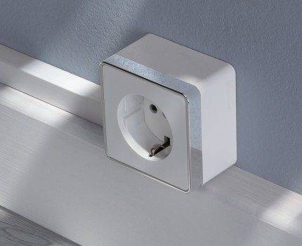
Since the installation is not carried out in an installation box, ordinary dowel-nails are suitable for reliable fixing on a plane.
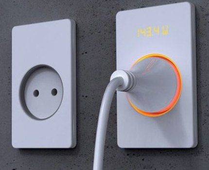
The built-in installation option has a more aesthetic appearance, because.the main part of the product is immersed in the wall, and only the protective case remains outside. Thus, nothing interferes with the perception of the interior of the room.
The wiring in this case is also rather hidden. For this type of fastening, a cylindrical hole is cut out in the wall, into which the installation box is mounted. It securely and securely fixes the socket in the wall.
According to the rules, it is recommended to install a device with a grounding contact at a distance of at least 500 mm from the gas pipeline
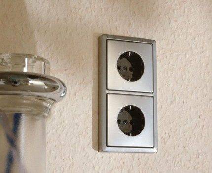
The version with two sockets is designed to connect two plugs to the network at once. With hidden installation, the block is placed in one socket box.
To increase their number (more than two), you will have to make an additional hole in the wall and combine the case with one frame if a hidden installation is supposed. If the model is consignment note, then modular blocks are added.
The European standard provides for the installation of an electric point at a height of 30 cm from the floor. This allows you to quickly find it in the dark by touch and comfortably use a person of average height.
A modern type of socket - with a grounding contact. It is used in networks with a ground wire, which are safer than networks of the "phase, zero" type.
Additional terminals are attached to this wire. They first of all come into contact with the connected plug, which eliminates the risk of dangerous voltage and current damage to faulty household appliances. It also protects the equipment from interference in the network and electromagnetic interference from other devices.
The antenna has no voltage. It is used to connect the TV to the antenna cable. External difference is only the type of inlet in the body.
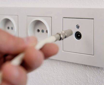
It makes sense to place the socket block behind the TV if the place of its installation is predetermined so as not to additionally clutter up the space with cables
A computer socket is used to connect to the Internet and local networks. You can also connect a telephone cable to it.


The Internet and telephone cable connectors are the same in shape - RJ45 and RJ11 / 12, respectively. The first uses 8 pins, and the second 4 or 6. But to connect to the Internet through a telephone jack, you will have to use a modem that uses a Dial-up connection.
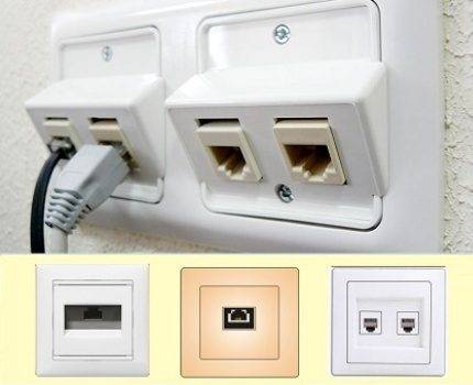
Manufacturers of Internet cables do not recommend twisting a twisted pair cable greater than 13 mm when connecting to avoid problems connecting to the Internet.
Such devices can be made in a compact package or look like a regular 220 V. To connect a phone with an old-style connector, you will have to install an outlet with the appropriate input.
Designation of sockets and switches on drawings and diagrams
The designation of sockets and other electrical equipment is applied to electrical diagrams, with the help of which installation work is carried out. Each element of the power supply system has a designation that allows it to be identified.
The procedure for indicating conventional signs on the diagrams is regulated by GOST. This standard has been published relatively recently. The new GOST replaced the old Soviet standard. According to the new rules, the pointers on the diagrams must match the regulated ones.
The inclusion of other equipment in the circuit must meet the requirements of GOST. This document sets standards for general use signs.The procedure for organizing the scheme of input-distribution devices is also regulated by GOST
Designations are made in the form of graphic symbols, which are the simplest geometric objects, including squares, rectangles, circles, lines and points. In certain combinations, these graphic elements indicate certain components of electrical appliances, machines and devices used in electrical engineering. In addition, symbols display the principles of system control.
Pointers on diagrams
Below is a graphic designation that is commonly used on working drawings.
Accessories are usually classified according to several criteria:
- degree of security;
- installation method;
- number of poles.
Due to different classification methods, there are differences among the symbols for connectors in the drawings.
Pointers on surface mounting drawings
The designations of the outlets in the drawing below indicate the following characteristics.
- duality, unipolarity and grounding;
- duality, unipolarity and lack of grounding contact;
- singleness, unipolarity and the presence of a protective contact;
- power socket with three poles and protection.
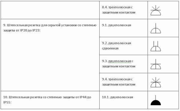
Directional signs for concealed installation
The picture below shows these outlets:
- single with one pole and grounding;
- paired with one pole;
- power with three poles;
- single with one pole and without protective contact.
Symbols for waterproof sockets
In the drawings, the following symbols for moisture-proof sockets are used:
- single with one pole;
- single with one pole and grounding device.
Pointers of the block of sockets and the switch
To save space, as well as to simplify the layout of electrical devices, they are often placed in a single unit. In particular, this scheme allows you to save on gating. Nearby there may be one or more outlets, as well as a switch.
The illustration below shows a socket and a single button switch.
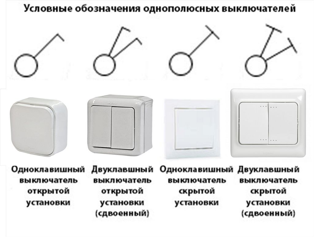
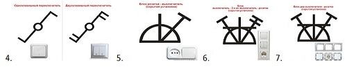
Pointers of switches with one and two keys
The picture below shows these switches:
- external;
- invoices;
- internal;
- embedded.
Below is a table that shows the conditional indicators of fittings.
The table shows a wide range of possible devices. However, the industry is releasing more and more new designs, so it often happens that new fittings have already appeared, but there are still no conventional signs for it.
0,00 / 0
220.guru
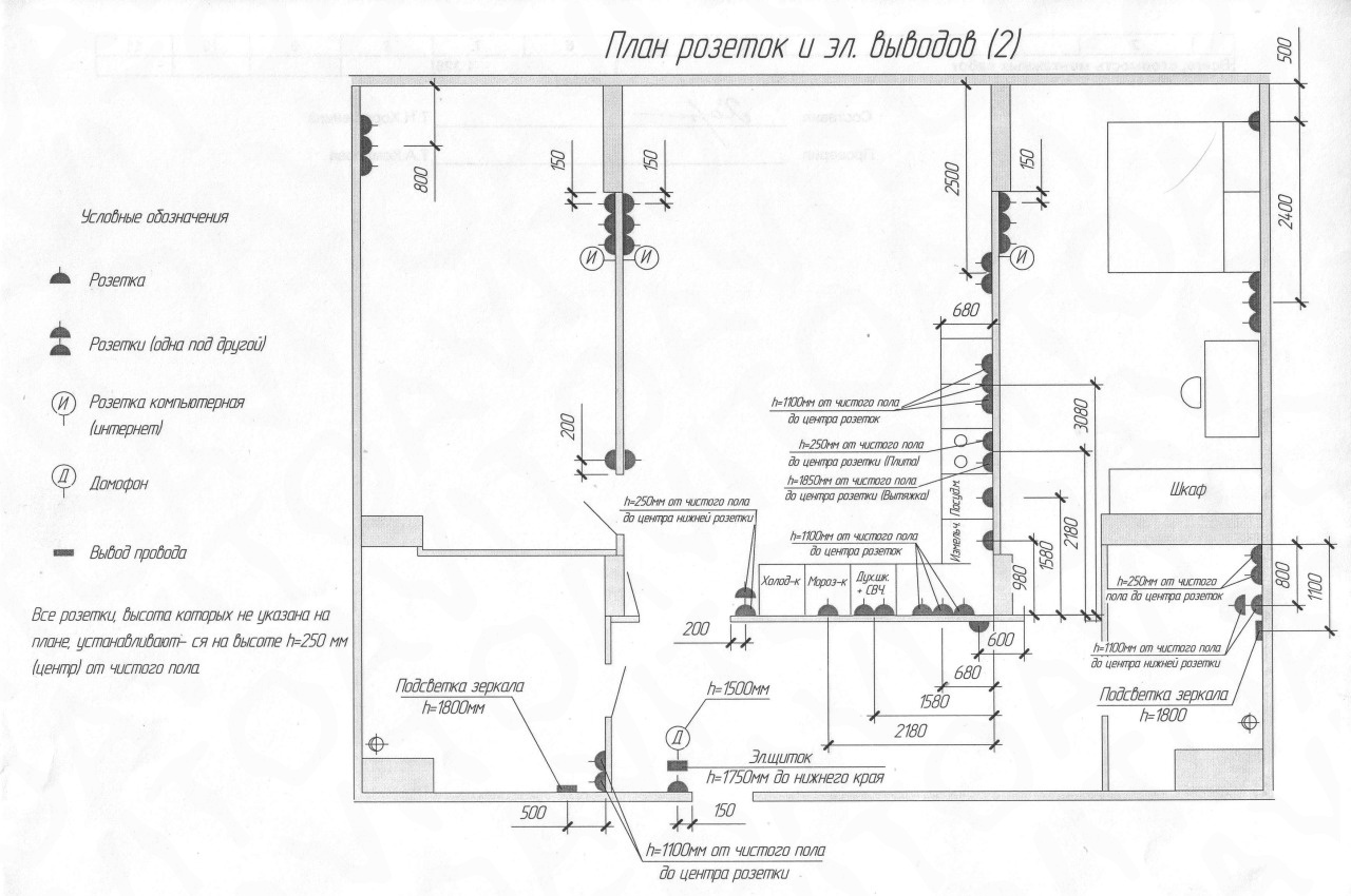
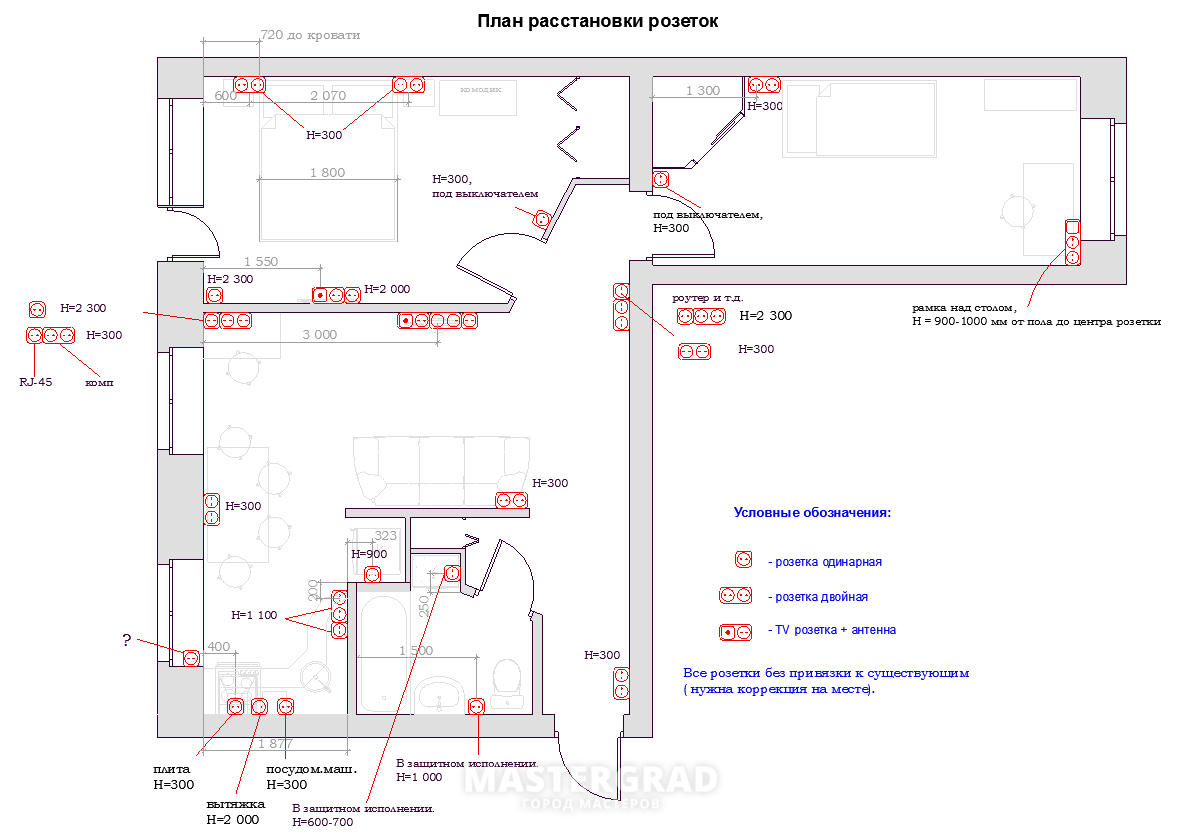
wiring diagram
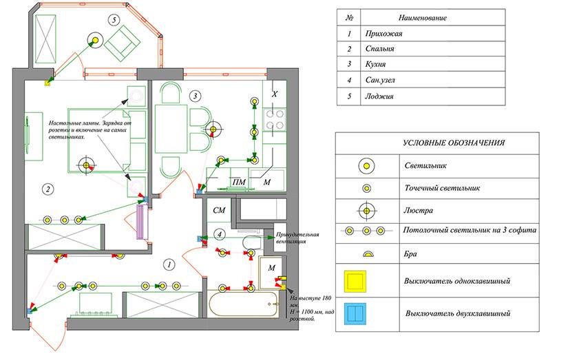
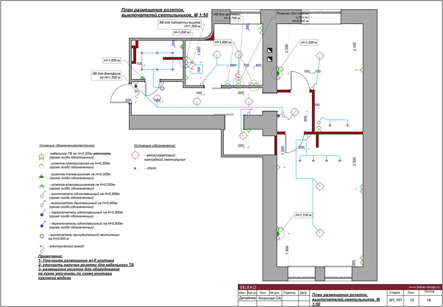
Drawing up a wiring diagram is necessary when building or overhauling a house. This scheme is carried out on the floor plan, indicating the height of the cable laying and the installation locations of machines, sockets and switches.
This plan will be used not only by the person who compiled it, but also by installers, and subsequently by electricians repairing electrical wiring. Therefore, the conditional images of sockets and switches in the drawings must be understandable to everyone and comply with GOST.
Designation of sockets on wiring diagrams
Outlet symbol - semicircle. The number and direction of the lines extending from it show all the parameters of these devices:
- For hidden wiring, the semicircle is intersected by a vertical line. It is absent in devices for open wiring;
- In a single outlet, one line goes up. In doubles - such a dash is doubled;
- A single-pole socket is indicated by one line, a three-pole socket - by three, diverging in a fan;
- Degree of weather protection. Devices with IP20 protection are depicted as a transparent semicircle, and with IP44-IP55 protection - this semicircle is painted over in black;
- The presence of grounding is indicated by a horizontal line. It is the same in devices of any configuration.
Symbol for sockets in the drawing
Interesting. In addition to electrical outlets, there are computer (for a LAN cable), television (for an antenna) and even vacuum ones, to which a hose from a vacuum cleaner is connected.


Designation of switches on the diagrams
Switches in all drawings look like a small circle with a dash inclined to the right at the top. It has extra lines on it. By the number and type of these dashes, you can determine the device parameters:
- a hook in the form of the letter “G” - an apparatus for open wiring, a transverse line in the form of the letter “T” - for hidden;
- one feature - a single-key switch, two - a two-key switch, three - a three-key switch;
- if the circle is solid, it is an IP44-IP55 weatherproof device.
Conventional designation of switches
In addition to conventional switches, there are pass-through and cross switches that allow you to control the light from several places. The designation of such devices in electrical circuits is similar to the usual ones, but there are two slashes: right-up and left-down. Conventional signs on them are duplicated.
Designation of the block of switches with a socket
For ease of use and a more aesthetic appearance, these devices are installed in adjacent mounting boxes and closed with a common cover. According to GOST, such blocks are designated in a semicircle, the lines on which correspond to each device individually.
The following figure shows two examples of switch and socket boxes:
- design for hidden wiring from a socket with an earthing contact and a double switch;
- design for flush wiring from a socket with an earthing contact and two switches: double and single.
Designation of the block of switches with a socket
Symbols for other devices
In addition to sockets and switches, other elements that have their own designations are also used in wiring diagrams.
The designation of protection devices: circuit breakers, RCDs and voltage monitoring relays is based on the image of an open contact.
The designation of the circuit breaker according to GOST consists of the required number of contacts connected to each other and a square on the side. This symbolizes the simultaneous operation of the protection systems. Introductory automata in apartments are usually two-pole, and single-pole ones are used to turn off individual loads.
Circuit breaker on conventional and single-line diagrams
There are no special designations according to GOST for RCDs and differential automata, so they reflect the design features. Such devices are a current transformer and an executive relay with contacts. In difavtomatah they added automatic protection against overload and short circuit.
Image of RCD and differential automaton on the diagrams
The voltage control relay turns off electrical appliances when the voltage deviates beyond the allowable limits. Such a device consists of an electronic board and a relay with contacts. This can be seen in the diagram of such devices.It is depicted on the top cover of the case.
Voltage control relay circuit
Graphic symbols of lighting and illumination devices, including LED chandeliers, symbolize the appearance and purpose of devices.
Symbols of fixtures
Knowledge of the symbols of sockets and switches and other equipment in the drawings is necessary when drafting, installing and repairing electrical wiring and other electrical equipment.
Socket symbol on the diagram
One of the most common household electrical outlets is the electrical outlet. On the diagram, it may look like various symbols, which depend on the type and design of this device.
The most important stage in the arrangement of electrical wiring is the preparation of a plan for the placement of all its elements.
Proper application of all the components of the electrical network to the electrical circuit ensures the correct planning of the required amount of materials, as well as a high level of electrical safety.
Advice
A properly drawn up scheme greatly facilitates the selection of the types of equipment required.
The electrical wiring plan is drawn up taking into account the scale of the premises and the features of its layout.
Guidance Documents
In order to unify the designations used in electrical circuits, back in Soviet times, GOST 21.614-88 “Conventional graphic images of electrical equipment and wiring on plans” was adopted.


In accordance with this document, the simplest geometric shapes are used to designate all elements of the electrical network, which make it easy to apply, as well as identify one or another element on the electrical circuit.
Strict requirements for the implementation of such drawings eliminate confusion and double interpretation of all symbols printed on the diagram, which is extremely important when performing installation work in the electrical network
Designations of elements of open installation
The simplest two-pole electrical outlet of an open installation without a grounding contact is depicted on the electrical circuit in the form of a semicircle with a line drawn perpendicular to its convex part.
The designation of a double socket differs from the previous one by the presence of two parallel lines. The graphic symbol corresponding to a three-pole product is a semicircle, the convex part of which is adjoined by three lines converging at one point and fanned out.
Sockets for concealed wiring
Concealed wiring is the most common type of home electrical network. For its laying, devices are used that are built into the wall using special mounting boxes.
The only difference between the designation of such sockets and the above figure is the perpendicular, which is lowered from the middle of the straight segment to the center of the circle.
Devices with increased protection against dust and moisture
The considered sockets do not differ in a high level of protection against the penetration of solid objects into their housing, as well as moisture. Such products can be used indoors, where operating conditions preclude such effects.
As for devices intended for installation outdoors or, for example, in bathrooms, according to the accepted classification, their degree of protection should be below IP44 (where the first digit corresponds to the level of protection against dust, the second - against moisture).
Such sockets are indicated on the diagram in the form of a semicircle completely filled in black. As in the previous case, two-pole and three-pole waterproof sockets are indicated by the corresponding number of segments adjacent to the convex part of the semicircle.
switches
The switch in the diagram is indicated in the form of a circle, to which a line is drawn at an angle of 45 with an inclination to the right, having one, two or three perpendicular segments at the end (depending on the number of keys of the depicted switch).
The image of flush-mounted switches is the same, only the segments at the end of the slash are drawn to both sides of it at the same distance.
It is worth paying attention to the image of the switches, which resembles two ordinary switches, mirrored from the center of the same circle.
Socket blocks
Often, in terms of a home electrical network, it is necessary to provide for the installation of blocks that include a different number of the most common elements - sockets and switches.
The simplest block, containing a two-pole socket in its composition, and a single-gang flush-mounted switch is depicted as a semicircle, from the center of which a perpendicular is drawn, as well as a line at an angle of 45, corresponding to a single-gang switch.
Similarly, blocks containing a different number of sockets and switches are applied to the diagram. For example, a flush-mounted unit, which includes a two-pole socket, as well as one-gang and two-gang switches, has the designation:


