- Installation of galvanized air ducts
- Materials used
- Design value of wind load
- Frequently asked questions (FAQ)
- How many fasteners are required
- GENERAL INSTRUCTIONS
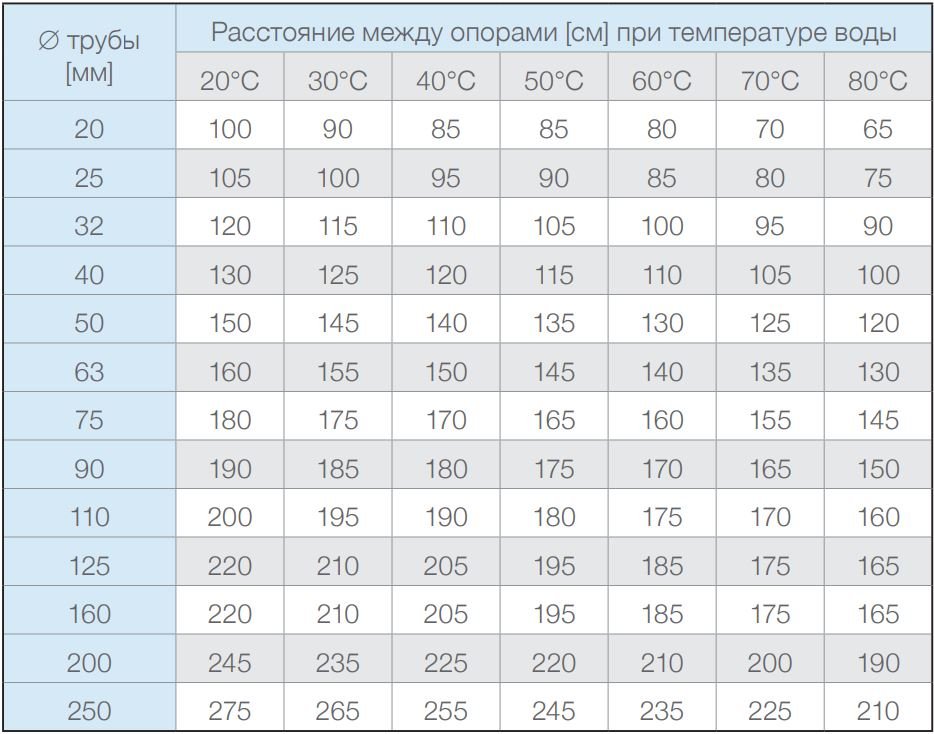
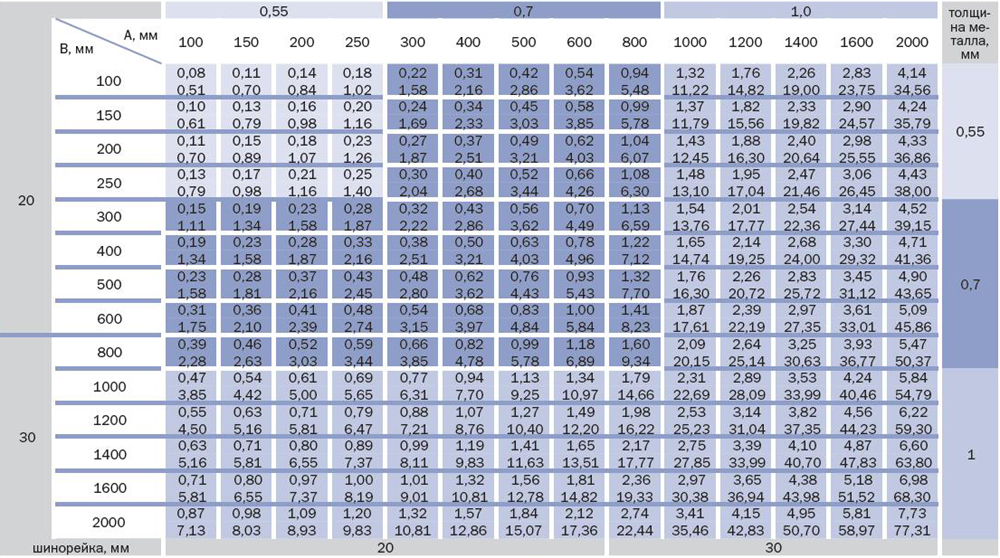
- Standard distances
- Installation of an insulated duct
- Flexible duct installation
- Total air exchange calculation
- Air Velocity Calculation Algorithm
- The subtleties of choosing an air duct
- Do-it-yourself manufacturing
- Ventilation shaft device
- Height
- Material
- fire safety
- How to calculate the pressure in the ventilation network
- Speed - 0.4 meters per second
- Speed - 0.8 meters per second
- Speed - 1.20 meters per second
- Speed - 1.60 meters per second
- Rules for the use of measuring devices
Installation of galvanized air ducts
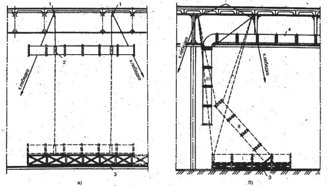
| When mounting rectangular air ducts made of galvanized steel, traverses are used - a straight rigid profile, horizontally suspended on studs. |
Installation of galvanized air ducts is the most common operation performed during the installation of ventilation systems. Galvanized steel air ducts are rigid air ducts of a certain length (usually 2 or 3 meters). Depending on the section, galvanized air ducts can be round or rectangular.In some cases, the installation of a round duct differs from that of a rectangular duct. So, the installation of round air ducts is often carried out using clamps, which are suspended from the ceiling with the help of studs. When mounting rectangular ducts made of galvanized steel, so-called traverses are used - a straight rigid profile, horizontally suspended on studs. With the help of nuts, the height of the suspension of the traverse is adjusted. Next, the air duct is placed on top of the traverse. In any case, between the air duct and the support, whether it be a clamp or a traverse, a rubber insert is laid, damping the vibrations of the air duct.
Materials used
The materials used for the production of different types of ducts depend on the specific application and the characteristics of the ventilation system.
are operated for air transfer in a temperate climate without an aggressive environment (temperature up to +80 ° C). Zinc coating contributes to the protection of steel from corrosion, which significantly extends the service life, but increases the cost of such products. Due to the resistance to humidity, mold will not appear on the walls, which makes them attractive for use in places with high humidity in the ventilation system (residential premises, bathrooms, catering places).
Stainless steel air ducts
are used to transfer air masses at temperatures up to +500 ° C. Heat-resistant and fine-fiber steel, up to 1.2 mm thick, is used in production, which makes it possible to operate this type of air duct even in aggressive environments. The main places of application are heavy industry plants (metallurgy, mining, with an increased radiation background).
Metal-plastic type of air ducts
are made using two metal layers, for example, with foamed plastic sandwiched between them. This design has high strength characteristics with a small mass, has an aesthetic appearance and does not require additional thermal insulation. The downside is the high cost of these products.
Also, special popularity in the conditions of transfer of aggressive air environments received .
The main industries in this case are chemical, pharmaceutical and food. Modified polyvinyl chloride (PVC) is used as the main material, which resists moisture, acid and alkali fumes well. Plastic is a light and smooth material that provides a minimum of pressure losses in the air flow and tightness in the joints, due to which a large number of various connecting elements are made from plastic, such as elbows, tees, bends.
Other types of ducts such aspolyethylene ducts,
find their application in ventilation systems.Air ducts fromfiberglass are used for joining the fan with air distributors.Air ducts fromvinyl plastic serve in aggressive environments with the content of acid vapors in the air, which contribute to the corrosion of steel. These types of air ducts have high corrosion resistance, are light in weight and can be bent in any plane to any angle.
Design value of wind load
The standard value of the wind load (1) is:
\({w_n} = {w_m} + {w_p} = 0.1 + 0.248 = {\rm{0.348}}\) kPa. (twenty)
The final calculated value of the wind load, by which the forces in the sections of the lightning rod will be determined, is based on the standard value, taking into account the reliability factor:
\(w = {w_n} \cdot {\gamma _f} = {\rm{0.348}} \cdot 1.4 = {\rm{0.487}}\) kPa. (21)
Frequently asked questions (FAQ)
What does the frequency parameter in formula (6) depend on?
the frequency parameter depends on the design scheme and the conditions for its fixing. For a bar with one end rigidly fixed and the other free (cantilever beam), the frequency parameter is 1.875 for the first mode of vibration and 4.694 for the second.
What do the coefficients \({10^6}\), \({10^{ - 8}}\) mean in formulas (7), (10)?
these coefficients bring all parameters to one unit of measure (kg, m, Pa, N, s).
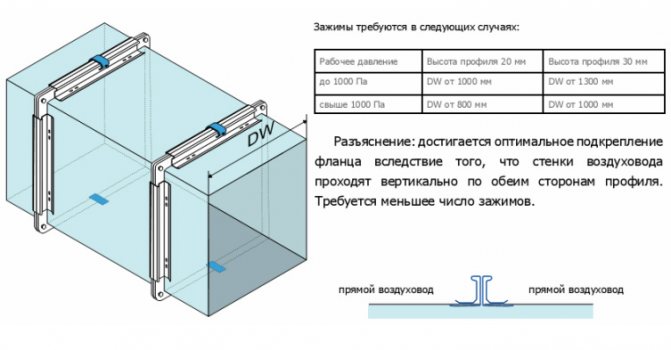
How many fasteners are required
The type of fasteners and their number are determined at the design stage, taking into account the mass, size, location of different types of air ducts, materials of manufacture, type of ventilation system, etc. If you plan to deal with these issues yourself, you will need to perform calculations and use reference data.
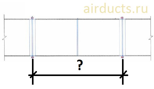
The consumption rates of fasteners are calculated based on the surface area of the air ducts. Before you can calculate the surface area, you need to determine the length of the duct. It is measured between two points where the center lines of the highways intersect.
If the duct has a circular cross section, its diameter is multiplied by the previously obtained length. The surface area of a rectangular duct is equal to the product of its height, width and length.
All calculations are made at a preliminary stage, the data obtained is used during installation, marking helps to observe the calculated distances, avoiding errors
Further, you can use reference data, for example, standard indicators of material consumption (NPRM, collection 20) approved by the Ministry of Construction of the Russian Federation. To date, this document has the status of invalid, but the data indicated in it for the most part remain relevant and are used by builders.


The consumption of fasteners in the directory is indicated in kg per 100 sq. m. surface area. For example, for round rebate air ducts of class H, made of sheet steel, 0.5 mm thick and having a diameter of up to 20 cm, 60.6 kg of fasteners per 100 square meters will be required. m.
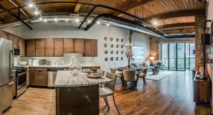
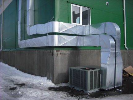
A properly designed and installed air duct system not only functions flawlessly, but also organically complements the interior of a modern home.
When installing air ducts, straight sections of air ducts, together with bends, tees and other shaped elements, are assembled into blocks up to 30 meters long. Further, in accordance with the standards, fasteners are installed. Prepared air duct blocks are installed in the places intended for them.
The following article will acquaint you with the regulatory requirements for the organization of ventilation in a private house, which is worth reading for all owners of suburban property.
GENERAL INSTRUCTIONS
1. GENERAL INSTRUCTIONS
1.1. The rules of this chapter apply to the production and acceptance of work on the installation of furnaces with fire furnaces: heating, heating and cooking, cooking stoves, etc., as well as smoke and ventilation ducts in the construction of residential and public buildings. Notes:
1. Factory production of furnaces, blocks and metal parts for them and for chimneys is not considered in this chapter.
2.The rules regarding the use of gas fuel in stoves, cookers and other household appliances are given in chapter SNiP III-G.2-62 “Gas supply. Internal devices. Rules for the production and acceptance of work.
1.2. The placement of stoves, stoves, chimneys and similar devices in the building plan should be carried out in accordance with the architectural and construction project, and their laying should be carried out according to standard or working drawings included in the project. The execution of stoves, stoves, etc. without the corresponding drawings are not allowed. When performing furnace work, no deviations from fire safety requirements are allowed.
1.3. The laying of stoves should be carried out by stove workers who have a certificate issued by the departmental qualification commission for the right to carry out stove work.
1.4. Furnace work should be carried out according to the work production project using advanced labor methods, rational tools, inventory and fixtures.
Standard distances
Air channels are fastened to different surfaces:
- ceiling plate
- ceiling trusses or load-bearing elements attached to them
- walls
- floor
When installing the system, the following regulations must be observed:
- the distance from round air ducts to the ceiling must be at least 0.1 m, and to walls or other elements - at least 0.05 m
- the distance between round air ducts and communications (water supply, ventilation, gas lines), as well as between two round air ducts should not be less than 0.25 m
- from the surface of the duct (round or rectangular) to electrical wires must be at least 0.3 m
- distances from the surface of rectangular air ducts to the ceiling must be at least 0.1 m (for air ducts with a width of up to 0.4 m), at least 0.2 m (for ducts with a width of 0.4-0.8 m) and at least 0 .4 m (for air ducts 0.8-1.5 m wide)
- all channel connections are made no closer than 1 m from the point of passage through walls, ceilings or other elements of the building structure
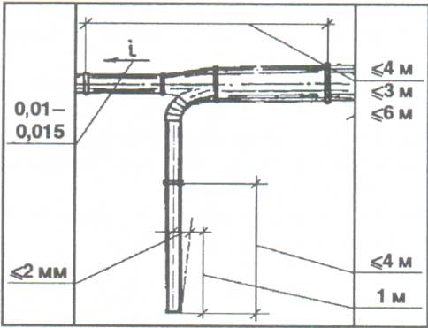
The axes of the air channels must be parallel to the planes of the ceiling plates or walls. Exceptions are cases of transition of channels from one level to another or in the presence of equipment, protruding structural elements of the building, which do not allow the installation of air ducts parallel to the plane of the building structure.
In addition, it is allowed to install pipelines with a slope of 0.01-0.015 towards drainage devices, if the transported medium is prone to condensate.
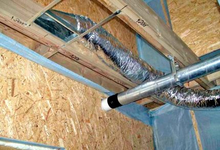
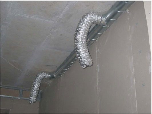
Installation of an insulated duct
The installation of a heat-insulated duct is carried out in a similar way, but there are some peculiarities: when cutting or connecting the sleeve, you must first unscrew the insulating layer, then cut / connect the inner frame to the flange, seal the connection, then return the thermal insulation to its place, re-fix it and insulate.
To isolate the external layer, aluminum tape and clamps are used, which are designed to connect the heat-insulating shell with the body of the duct.
When installing a soundproof duct, it must be taken into account that the “weak” point may be the flange connection. For higher noise absorption, the air duct is completely put on the branch pipe (without gaps). The joints are also sealed with aluminum tape and clamps.
Flexible duct installation
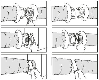
A flexible and semi-rigid air duct with a small cross section is usually installed in apartments and small cottages. Installation of a flexible duct is carried out in several stages.
- Highway marking. The ventilation and air conditioning system is usually installed according to the design drawings, which indicate the paths for laying the air ducts. We draw a line on the ceiling (with a pencil or marker), along which the channel will pass.
- Fixing installation. To prevent possible sagging, we fix the dowels every 40 cm of our line and fix the clamps on them.
- We determine the required length of the duct and measure the duct sleeve. It is necessary to measure the "pipe" at its maximum tension.
- If you need to cut off the excess part of the duct, you can use a sharp knife or scissors and bite the wire (frame) with wire cutters. Cut insulation only with gloves.
- If it is necessary to increase the length of the air duct, the opposite parts of the sleeve are put on the connecting flange and fastened with clamps.
- The end of the sleeve is connected to the branch pipe or flange of the ventilation grill (or fixed at the place of its future installation).
- The rest of the hose is pulled under tension through the prepared clamps to the point of connection with the central ventilation line.
- If the project provides for several ventilation openings, then a separate outlet is created for each of them.
Total air exchange calculation
The formula for calculating air exchange by multiplicity.
When determining it, one should proceed primarily from what type of room and its dimensions. The intensity of air exchange varies significantly in residential, office, industrial premises.It also depends on the number of people and the time during which they are in them.


In addition, the calculation of air exchange depends on the power of the fan and the air pressure that it creates; diameter of air ducts and their length; the presence of recirculation, recovery, supply and exhaust ventilation or air conditioning systems.
In order to correctly equip the ventilation system, you first need to determine what the room needs for complete air exchange for 1 hour. For this, indicators of the so-called air exchange rate are used. These constant values have been established as a result of research and correspond to different types of premises.
So, for example, the air exchange rate per 1 m² of a storage room is 1 m³ per hour; living room - 3 m³ / h; cellars - 4-6 m³ / h; kitchens - 6-8 m³ / h; toilet - 8-10 m³ / h. If we take large premises, then these figures are: for a supermarket - 1.5-3 m³ per person; school class - 3-8 m³; cafe, restaurant - 8-11 m³; conference-cinema or theater hall - 20-40 m³.
For calculations, the formula is used:
L \u003d V x Kr,
where L is the volume of air for complete air exchange (m³/h); V is the volume of the room (m³); Kr is the air exchange rate. The volume of a room is determined by multiplying its length, width and height in meters. The air exchange rate is selected from the relevant tables.
Table for calculating the throughput of the duct.
A similar calculation can be made using another formula, which takes into account air standards for 1 person:
L = L1 x NL,
where L is the volume of air for complete air exchange (m³/h); L1 - its normative amount per 1 person; NL is the number of people in the room.
The air standards for 1 person are as follows: 20 m³ / h - with low physical mobility; 45 m³ / h - with light physical activity; 60 m³ / h - for heavy physical exertion.
Air Velocity Calculation Algorithm
Given the above conditions and the technical parameters of a particular room, it is possible to determine the characteristics of the ventilation system, as well as calculate the air velocity in the pipes.
You should rely on the frequency of air exchange, which is the determining value for these calculations.
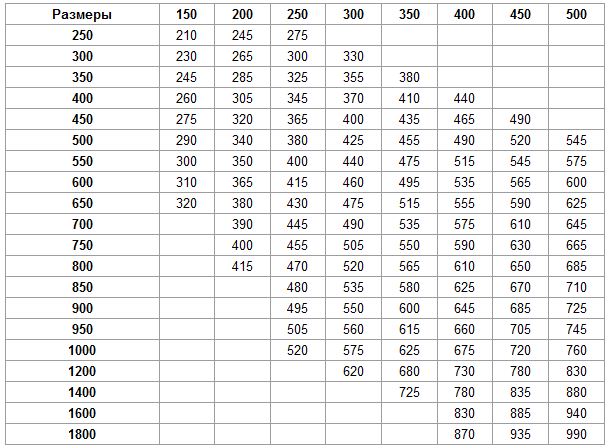
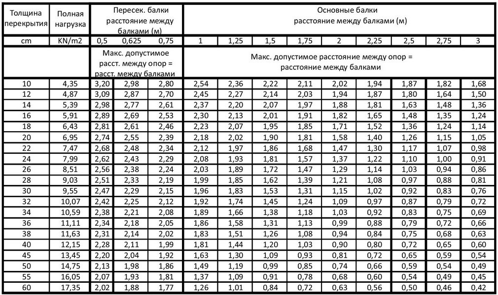
To clarify the flow parameters, a table is useful:
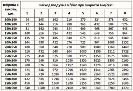 The table shows the dimensions of rectangular ducts, that is, their length and width are indicated. For example, when using ducts 200 mm x 200 mm at a speed of 5 m/s, the air flow will be 720 m³/h
To independently make calculations, you need to know the volume of the room and the rate of air exchange for a room or hall of a given type.
For example, you need to find out the parameters for a studio with a kitchen with a total volume of 20 m³. Let's take the minimum multiplicity value for the kitchen - 6. It turns out that within 1 hour the air channels should move about L = 20 m³ * 6 = 120 m³.
It is also necessary to find out the cross-sectional area of the air ducts installed in the ventilation system. It is calculated using the following formula:
S = πr2 = π/4*D2,
where:
- S is the cross-sectional area of the duct;
- π is the number "pi", a mathematical constant equal to 3.14;
- r is the radius of the duct section;
- D is the diameter of the duct section.
Let's assume that the diameter of the round duct is 400 mm, we substitute it into the formula and get:
S \u003d (3.14 * 0.4²) / 4 \u003d 0.1256 m²
Knowing the cross-sectional area and flow rate, we can calculate the speed.The formula for calculating the airflow rate:
V=L/3600*S,
where:
- V is the speed of the air flow, (m/s);
- L - air consumption, (m³ / h);
- S - cross-sectional area of air channels (air ducts), (m²).
We substitute the known values, we get: V \u003d 120 / (3600 * 0.1256) \u003d 0.265 m / s
Therefore, in order to provide the required air exchange rate (120 m3/h) when using a round duct with a diameter of 400 mm, it will be necessary to install equipment that allows increasing the air flow rate to 0.265 m/s.
It should be remembered that the factors described earlier - the parameters of the vibration level and the noise level - directly depend on the speed of air movement.
If the noise exceeds the norm, you will have to reduce the speed, therefore, increase the cross section of the ducts. In some cases, it is enough to install pipes from a different material or replace the curved channel fragment with a straight one.


The subtleties of choosing an air duct
Knowing the results of aerodynamic calculations, it is possible to correctly select the parameters of air ducts, or rather, the diameter of round and dimensions of rectangular sections. In addition, in parallel, you can select a device for forced air supply (fan) and determine the pressure loss during the movement of air through the channel.
Knowing the amount of air flow and the value of the speed of its movement, it is possible to determine what section of the air ducts will be required.
For this, a formula is taken that is the inverse of the formula for calculating the air flow:
S=L/3600*V.
Using the result, you can calculate the diameter:
D = 1000*√(4*S/π),
where:
- D is the diameter of the duct section;
- S - cross-sectional area of air channels (air ducts), (m²);
- π is the number "pi", a mathematical constant equal to 3.14;.
The resulting number is compared with factory standards approved by GOST, and the products closest in diameter are selected.
If it is necessary to choose rectangular rather than round ducts, then instead of the diameter, determine the length / width of the products.
When choosing, they are guided by an approximate cross-section, using the principle a * b ≈ S and tables of standard sizes provided by manufacturers. We remind you that according to the norms, the ratio of width (b) and length (a) should not exceed 1 to 3.
Air ducts with a rectangular or square section are ergonomically shaped, which allows them to be installed close to walls. They use this when equipping home hoods and masking pipes over ceiling hanging structures or over kitchen cabinets (mezzanines)
Generally accepted standards for rectangular ducts: minimum dimensions - 100 mm x 150 mm, maximum - 2000 mm x 2000 mm. Round ducts are good because they have less resistance, respectively, have minimal noise levels.
Recently, convenient, safe and lightweight plastic boxes have been produced especially for intra-apartment use.
Do-it-yourself manufacturing
We propose to explain the cap assembly technology using the example of a TsAGI-type nozzle. Details are cut out of galvanized steel 0.5 mm thick, fastened together with rivets or bolts with nuts. The design of the exhaust element is shown in the drawing.
For manufacturing, you will need a regular locksmith tool:
- hammer, mallet;
- metal scissors;
- electric drill;
- vise;
- marking devices - scriber, tape measure, pencil.
The table below shows the dimensions of the deflector parts and the final weight of the product.
The assembly algorithm is the following.According to the scans, we cut out the blanks of the umbrella, diffuser and shell with scissors, fasten them together with rivets. Cutting the shells is not difficult, the diffuser and umbrella sweeps are shown in the drawings.
Open the lower glass - an expanding diffuser
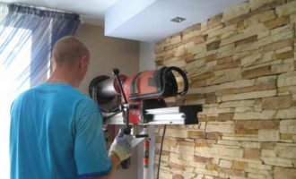
The finished deflector is mounted on the head, the lower pipe is pulled together with a clamp. For a square shaft, you will have to make or buy an adapter, whose flange is attached to the end of the pipe.
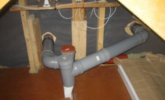
Ventilation shaft device
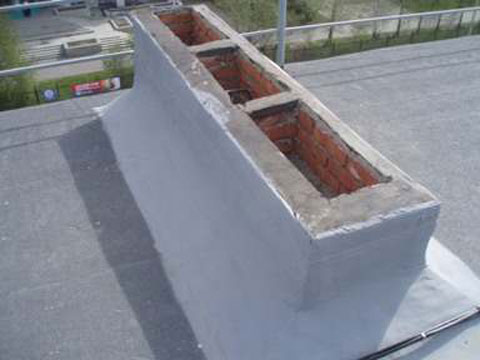
The structure, as a rule, looks like a cylindrical trunk. It is located strictly vertically and contains three parts:
- one large one - about 300x600 mm;
- two small ones - about 150 mm.
It is the large part that is the trunk, which crosses all the floors of the building, from the basement to the attic.
The design may be non-standard. Increased dimensions must be taken into account when selecting fans.
Through special windows located in rooms such as a kitchen or a bathroom, polluted air enters not very large channels and, rising through them to a height of about three meters, ends up in a common shaft. Thanks to such a device, the distribution of used air through the duct from one room to another, for example, from the kitchen to the bathroom, and then to the rooms, is practically excluded.
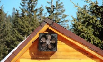
In outbuildings, say, farms or poultry farms, the ventilation shaft near the ridge is considered an ideal design option that provides air circulation. They run the entire length of the roof of the building in the direction of the ridge.


To close access to raindrops of rain, an umbrella is mounted above the outlet of the box. As a rule, in natural air exchange structures, a deflector is mounted directly on the wellhead.With gusts of wind, a rarefaction is created here, which contributes to increased traction. But first of all, of course, the deflector does not allow the air flow to “tip over” in the box
When calculating the system, the vacuum created by the wind is not taken into account.
Variants with artificial air exchange, which contribute to the removal of aggressive air impurities of the first and second classes, work somewhat differently: polluted air is thrown out to a fairly significant height. Such an emission is also called a flare.
Height
When placing an exhaust duct on the roof of a building, the smallest allowable distance between it and the air intake of the supply system must be taken into account. According to SNiP:
- horizontally it is equal to ten meters,
- vertically, respectively, six.
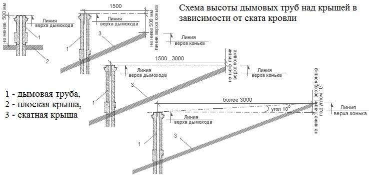
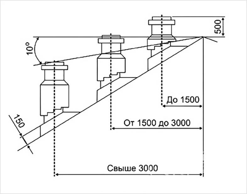
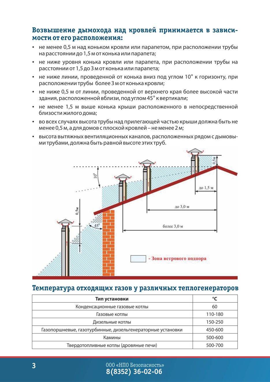
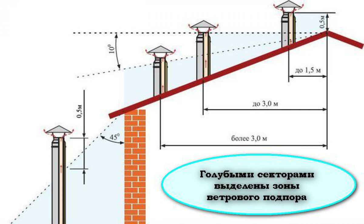
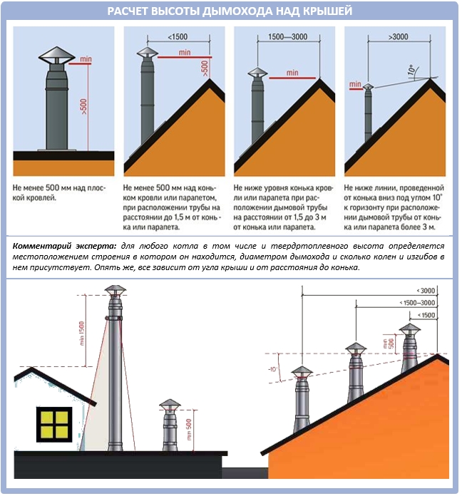
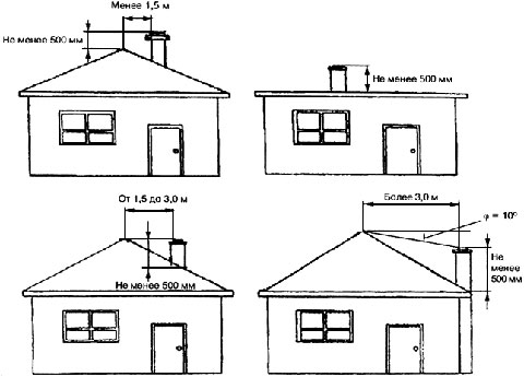
The height of the ventilation shaft above the roof is determined by the following conditions:
- when it is located near the ridge, the mouth, that is, the hood opening must be at least half a meter higher than the ridge;
- when located at a distance of one and a half to three meters from the ridge, the hole is flush with the ridge;
- for distances over three meters, the hole is led out along the side of the angle of 10⁰ to the horizon with the top on the ridge.
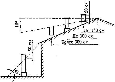
The height of the mouth above the roof for a standard design is usually chosen to be 1 m, in the case of a flare, at least 2 m above the highest point of the roof. For emergency - the mine is raised to a height of at least 3 m from the ground.
Material
In residential and public buildings with a system of combined exhaust ducts, lightweight concrete, brick, boards, upholstered with galvanized inside are most often used.The trunk of the passage from the inside is preliminarily covered with felt, which is dipped in a clay solution and plastered on the outside. In industrial buildings, the exhaust structure is mainly made of sheet steel.
fire safety
When organizing the ventilation of a building, all rooms and floors are connected to each other by a network of channels and air ducts, which in itself is dangerous from the point of view of fire safety. Therefore, these elements themselves and the gaskets between them are made of materials that meet the SNiP, according to which explosion and fire safety is ensured. In particular, the shaft is separated from the air duct by a partition made of non-combustible and moisture-resistant material.
How to calculate the pressure in the ventilation network
In order to determine the expected pressure for each individual section, you must use the formula below:
H x g (PH - PB) \u003d DPE.
Now let's try to figure out what each of these abbreviations means. So:
- H in this case denotes the difference in the marks of the mine mouth and the intake grate;
- РВ and РН is an indicator of gas density, both outside and inside the ventilation network, respectively (measured in kilograms per cubic meter);
- Finally, DPE is a measure of what the natural available pressure should be.
We continue to disassemble the aerodynamic calculation of air ducts. To determine the internal and external density, it is necessary to use a reference table, and the temperature indicator inside / outside must also be taken into account. As a rule, the standard temperature outside is taken as plus 5 degrees, and regardless of in which particular region of the country construction work is planned.And if the temperature outside is lower, then as a result the injection into the ventilation system will increase, due to which, in turn, the volumes of incoming air masses will be exceeded. And if the temperature outside, on the contrary, is higher, then the pressure in the line will decrease because of this, although this trouble, by the way, can be completely compensated by opening the vents / windows.
As for the main task of any described calculation, it consists in choosing such air ducts where the losses on the segments (we are talking about the value ? (R * l *? + Z)) will be lower than the current DPE indicator or, alternatively, at least equal to to him. For greater clarity, we present the moment described above in the form of a small formula:
DPE? ?(R*l*?+Z).
Now let's take a closer look at what the abbreviations used in this formula mean. Let's start from the end:
- Z in this case is an indicator indicating a decrease in air speed due to local resistance;
- ? - this is the value, more precisely, the coefficient of what is the roughness of the walls in the line;
- l is another simple value that indicates the length of the selected section (measured in meters);
- finally, R is an indicator of friction losses (measured in pascals per meter).
Well, we figured it out, now let's find out a little more about the roughness index (that is,?). This indicator depends only on what materials were used in the manufacture of channels. It is worth noting that the speed of air movement can also be different, so this indicator should also be taken into account.
Speed - 0.4 meters per second
In this case, the roughness index will be as follows:
- for plaster with the use of reinforcing mesh - 1.48;
- for slag gypsum - about 1.08;
- for an ordinary brick - 1.25;
- and for cinder concrete, respectively, 1.11.
With this, everything is clear, let's move on.
Speed - 0.8 meters per second
Here, the described indicators will look like this:
- for plaster with the use of reinforcing mesh - 1.69;
- for slag gypsum - 1.13;
- for ordinary brick - 1.40;
- finally, for slag concrete - 1.19.
Let's slightly increase the speed of the air masses.
Speed - 1.20 meters per second
For this value, the roughness indicators will be as follows:
- for plaster with the use of reinforcing mesh - 1.84;
- for slag gypsum - 1.18;
- for an ordinary brick - 1.50;
- and, consequently, for slag concrete - somewhere around 1.31.
And the last indicator of speed.
Speed - 1.60 meters per second
Here the situation will look like this:
- for plaster using a reinforcing mesh, the roughness will be 1.95;
- for slag gypsum - 1.22;
- for ordinary brick - 1.58;
- and, finally, for slag concrete - 1.31.
Note! We figured out the roughness, but it is worth noting one more important point: it is also desirable to take into account a small margin, fluctuating within ten to fifteen percent
Rules for the use of measuring devices
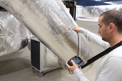
When measuring the air flow rate and its flow rate in the ventilation and air conditioning system, the correct selection of devices and compliance with the following rules for their operation are required.
This will allow you to get accurate results of the calculation of the duct, as well as to make an objective picture of the ventilation system.
 In order to fix the average flow rates, you need to perform several measurements. Their number depends on the diameter of the pipe or on the size of the sides, if the channel is rectangular
Follow the temperature regime, which is indicated in the device passport. Also keep an eye on the position of the probe sensor. It must always be oriented exactly towards the air flow.


If you do not follow this rule, the measurement results will be distorted. The greater the deviation of the sensor from the ideal position, the higher the error will be.