- Switching light from two places
- Wiring diagram for a two-gang pass-through switch
- Principle of operation
- Accession
- The principle of operation of the pass switch
- Connecting a two-gang light switch with a socket: decoding the circuit
- How does a two-button switch work?
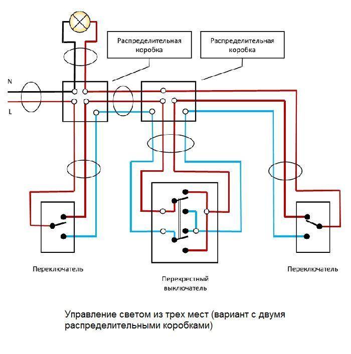
- Scheme of three-key equipment
- Where is the device placed?
- Installation of two-gang switch circuits
- Device design
- Marking on the switch housing
- Step-by-step instructions for installing a two-button switch on the hood and lighting in the bathroom
- Connecting switches to a socket
- Why Choose Double Key Switches
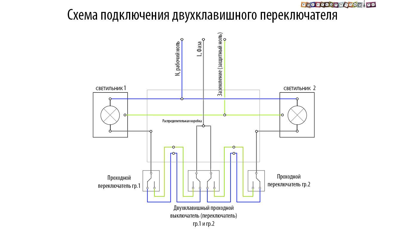
- Two-button walk-through switch: control of two groups of luminaires from several places
Switching light from two places
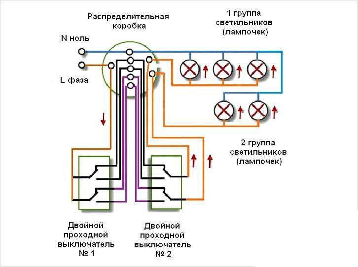
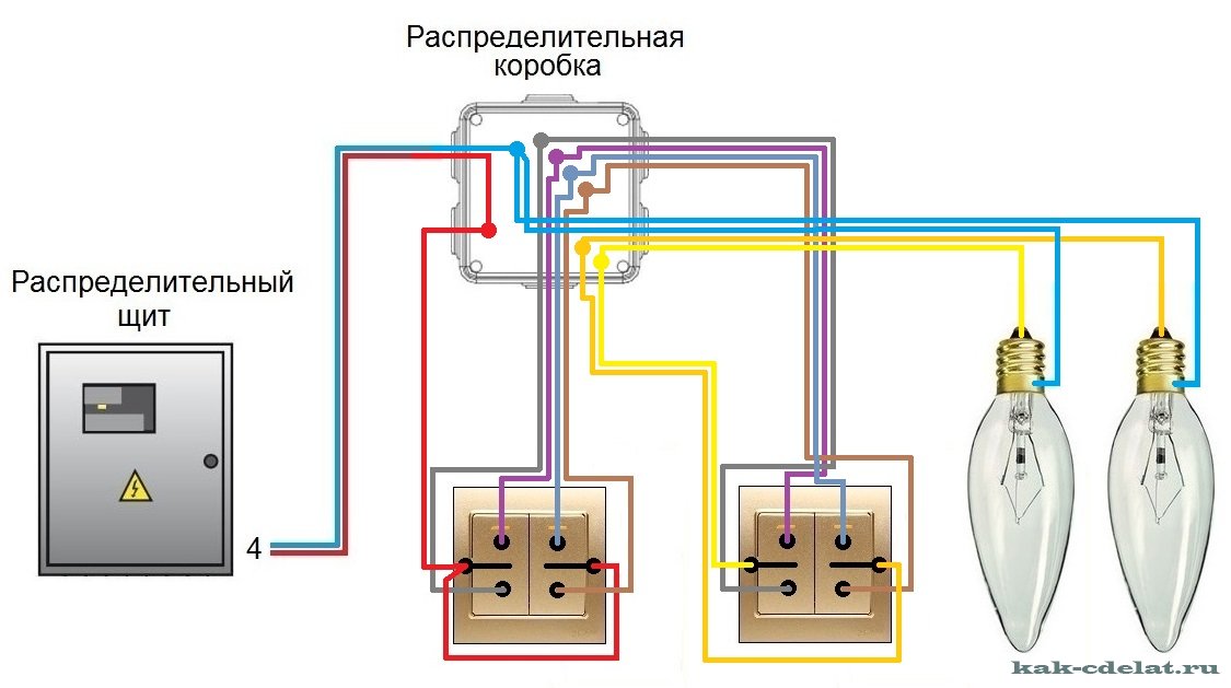
The lighting of the project corridor consists of two light groups, so it is logical in this case to use two two-button switches for control.
Accordingly, in addition to them, you will need:
- two sockets;
- one junction box;
- three-core cable.
The footage of electrical conductors should be calculated after drawing up the diagram and layout of the wiring. It is recommended to purchase a cable with a small margin.
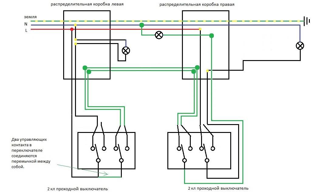
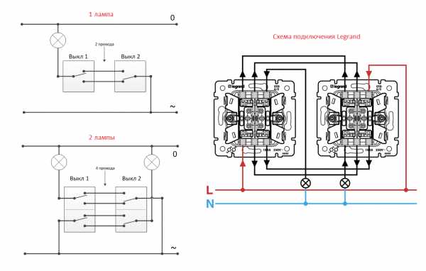
The control scheme for two light groups through two-button switches looks something like this:
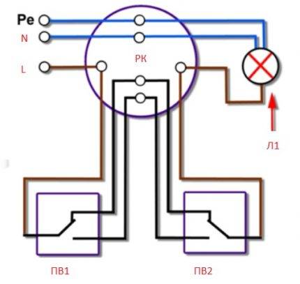
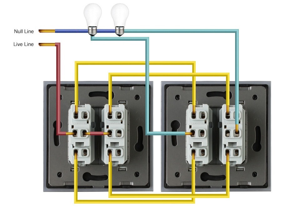
 Control scheme for two separate light groups through two-button devices: N, L - classical electrical network; RK - distribution box for cabling; L1, L2 - separate light groups; P - jumper; PV1, PV2 - two-gang pass-through switches (+)
The phase conductor is connected to the two-key device PV1. This switch, which has a two-button configuration, respectively, has two common contact terminals and four changeover contact terminals.
On the first device, the common terminals are connected together and the phase conductor is connected to them. Terminal 1 of the changeover contact PV1 is connected with a wire to terminal 1 of the changeover contact PV2. Accordingly, pin 2 of PV1 will be connected to terminal 2 of PV2, terminal 3 of PV1 to terminal 3 of PV2, and terminal 4 of PV1 to terminal 4 of PV2.
There are two more terminals on the second pass-through switch. Both are common (common), and they are connected according to the principle: each for one light group (L1 and L2) of the lighting system. Already from the light groups, the outgoing conductors close the circuit to the neutral bus of the electrical network.
However, this is only one of the possible circuit solutions. So, if one light group is used, it is possible to organize a circuit on single-gang switches.
Wiring using single-gang switches looks more economical in terms of material consumption. Less wire is required here, since the number of connecting lines is almost halved compared to the previous solution.
But, at the same time, the functionality of the lighting system itself is limited.
 Schematic solution for one light group using single-key switches: L, N, PE - classic power distribution for three lines; RK - junction box; L1 - light group; PV1, PV2 - single-key switches (+)
However, for a device in residential premises, this option can be used most often.
What is required for the device of the control system on single-gang switches?
The answer is obvious:
- single-key switches (2 pcs.);
- socket boxes (2 pcs.);
- junction box (1 pc.);
- three-core electric cable (meterage by calculation).
System requirements are standard. Before the start of work, a scheme is drawn up. The necessary accessories, materials, fasteners are purchased. Socket boxes and a distribution box are installed at the designated places.
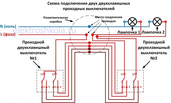
An example of a residential wiring device from the Standard Projects category. Two single-key switches are used. The solution is made taking into account the cabling with the earth conductor (PE). This option corresponds to the diagram shown above.
Then the cable is routed and connections are made between the walk-through switches from two places with the light source through the junction box.
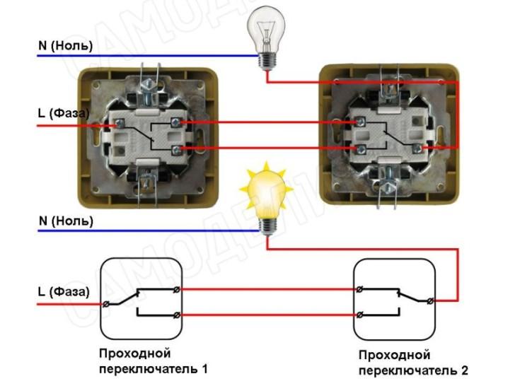
The phase conductor is connected to the common terminal PV2, and the common terminal PV1 is connected to one contact of the light group. The second contact of the light group is connected to the zero bus, and the changeover contacts of both switches are switched between themselves, observing identical numbering (1 with 1, 2 with 2).


Wiring diagram for a two-gang pass-through switch
Although the switch is usually installed at the entrance to the premises, there are situations when this does not suit users.So, when passing a long corridor at night, a person experiences significant inconvenience due to the fact that he must go most of the way in the dark if he enters from the other end of the room where there is no switch. To solve such problems, pass-through switches are produced, for example, by Legrand.
In the described example, to correct the situation, at different ends of the corridor it is necessary to install two pass-through switches, one of which turns on the light, and the other turns off the lighting and vice versa. Thanks to this switching, the entire path passes through the illuminated space, which is much more comfortable and safer.
Principle of operation
Unlike a standard two-button switch, there is no “on” and “off” position in the walk-through. Due to a different principle of operation of the mechanism, in it each key controls a changeover contact, that is, voltage is applied to one outgoing contact and the power is turned off at the same time from the other outgoing terminal. Two two-button devices control two different lamps/luminaire groups from two different locations in the room.
The main feature of mounting a pass-through switch with two keys is that one four-wire cable or two two-wire cables are laid between such switches. At the same time, as between single-gang switches, it is enough to lay a two-core cable.
Accession
The installation of a two-gang pass-through switch, or rather a pair of such devices, differs significantly from a standard switch. Therefore, it is recommended to print out the wiring diagram, mark / number all the wires laid, and then proceed strictly according to the diagram.Otherwise, some wire will definitely be mixed up and the switches will not work correctly.
The principle of operation of the pass switch
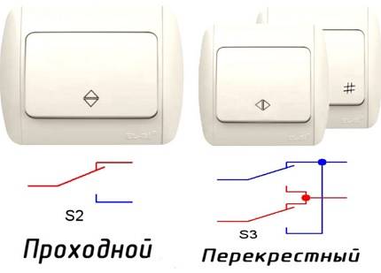
On the key of the pass-through switch there are two arrows (not large), directed up and down.
This type has a one-button switch. There may be double arrows on the key.
The connection diagram is not much more complicated than the connection diagram of a classic switch. The difference is only in a larger number of contacts: a conventional switch has two contacts, and a pass-through switch has three contacts. Two out of three contacts are considered common. In the lighting switching circuit, two or more similar switches are used.
Differences - in the number of contacts
The switch works as follows: when switching with the key, the input is connected to one of the outputs. In other words, the feed-through switch is designed for two operating states:
- Input connected to output 1;
- Input connected to output 2.
It has no intermediate positions, therefore, the circuit works as it should. Since there is a simple connection of contacts, according to many experts, they should have been called "switches". Therefore, the transitional switch can be safely attributed to such devices.
In order not to be mistaken what kind of switch, you should familiarize yourself with the switching circuit, which is present on the switch body. Basically, the circuit is available on branded products, but you will not see it on inexpensive, primitive models. As a rule, the circuit can be found on switches from Lezard, Legrand, Viko, etc.As for cheap Chinese switches, there is basically no such circuit, so you have to call the ends with the device.
This is the switch on the back.
As mentioned above, in the absence of a circuit, it is better to call contacts at different key positions. This is also necessary in order not to mix up the ends, since irresponsible manufacturers often confuse the terminals during the production process, which means that it will not work correctly.
To ring the contacts, you must have either a digital or pointer device. The digital device should be switched to dialing mode with the switch. In this mode, short-circuited sections of electrical wiring or other radio components are determined. When the ends of the probes are closed, the device emits a sound signal, which is very convenient, since there is no need to look at the device display. If there is a pointer device, then when the ends of the probes are closed, the arrow deviates to the right until it stops.
In this case, it is important to find a common wire. For those who have the skills to work with the device, there will be no particular problems, but for those who picked up the device for the first time, the task may not be solvable, despite the fact that you need to figure out only three contacts
In this case, it is better to first watch the video, which clearly explains, and most importantly shows how to do it.
Pass-through switch - how to find a common terminal?
Watch this video on YouTube
Connecting a two-gang light switch with a socket: decoding the circuit
In order to properly install the unit in which the socket and the switch button are combined, it is necessary to act according to the diagram below.
Wiring diagram for a two-key switch with a socket (unit with 1 key)
The algorithm of actions is as follows:
- a cable with two cores is removed from the main shield: phase and zero. It connects to the contacts in the junction box. By means of a double cable, a lamp and a switch with a socket are connected;
- three cables coming out of the installed unit come into the junction box. The luminaire is connected with one core to zero, and the second to the free terminal of the switch;
- if a grounding conductor is provided in the "socket + switch" block, it must be connected to the same conductor in the junction box.
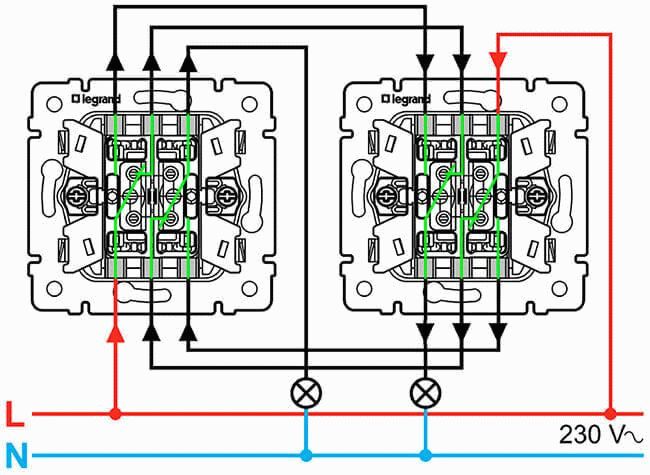
How does a two-button switch work?
The equipment has a total of 12 pins, 6 for each double switch (2 inputs, 4 outputs), therefore, to connect equipment of this type, you need to take 3 wires for each key of the device.
Switch Diagram:
Switch circuit
- the device consists of a pair of independent contacts;
- the upper contacts of the device N1 and N2 are switched to the lower ones by pressing the keys. The elements are connected by a jumper;
- the second contact of the right switch, shown in the diagram, is aligned with the phase;
- the contacts of the left mechanism do not intersect with each other, joining two different sources;
- The 4 cross contacts are combined in pairs.
The installation of a two-gang switch is carried out as follows:
- A pair of double mechanisms is installed in the sockets in selected areas.
- For each light source, a separate three-core cable is placed in the socket, the cores of which are cleaned of insulation by about 1 centimeter.
- In the diagram, the cable cores are designated as L (phase), N (working zero), ground (protective).
- The device is equipped with markings, which simplifies the task of connecting wires to the switch terminals. The wires are connected to the terminals in pairs.
- The bundle of wires is neatly placed in the socket, after which the switch mechanism, frame and cover of the protective housing are installed.
What the marking looks like:
Two-key switch marking
Connection diagram example:
Connection diagrams
To facilitate the work process, it is recommended to select wires of a certain light. There is a color marking of wires for Russia and other CIS countries. Also on it, a beginner can learn to distinguish between cables. According to the Russian marking for the “earth”, yellow and green colors are used, the neutral cable is usually marked in blue. The phase can be red, black or grey.


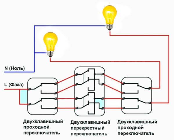
Scheme of three-key equipment
When installing a triple device, intermediate (cross) switches are used, which are connected between the two side elements.
Scheme of three-key equipment
This switch has two inputs and outputs. The cross element can translate both contacts at the same time.
Triple equipment assembly process:
- Ground and zero are connected to a light source.
- The phase is connected to the input of one of a pair of through structures (with three inputs).
- A free wire of the light source is connected to the input of another switch.
- Two outputs of one element having three contacts are combined with the input of a cross device (with two pairs of outputs).
- Two outputs of the pair mechanism (with three contacts) are combined with another pair of terminals of the next switch (with four inputs).
Where is the device placed?
As a rule, pass-through switches are mounted in different zones so that they are convenient to use. It is not necessary to use two switches. So, one of them can become the main, and the other auxiliary.
If the electrical wiring was located in a corrugated tube, then when installing a pass-through device, it will be possible to replace it without breaking the floors.
Wiring in a corrugated tube
Most often, standard walk-through switches with one or two keys are placed at such points:
- On both sides of a narrow corridor. If the door is located in the center, then it will also be possible to install the device near it.
- In spacious bedrooms. So, one switch can be installed according to the standard at a distance of 30-40 centimeters from the door jamb, and the other above the bed.
- On the landing.
- Along the path in the courtyard of a private house. After all, it will be convenient to go for a walk in the evening, and if necessary, turn on and off the light along the way.
- In the halls of a large area, where there are several entrances on the sides.
The use of a pass-through switch is advisable not only to save electricity, but also necessary for the safety of movement. It turns out that the only drawback is the complexity of the installation for some wizards.
Installation of two-gang switch circuits
We talked about the installation of single-key circuits above. For two-key, everything is a little different: there is no junction box, so the mechanism will be as follows:
- first, the switches themselves are installed in special boxes, the leads of which are left long enough;
- after that, lamps are installed, the contacts of which must also be of great length;
- connection is made in accordance with the diagram.
As you can see, there are no complex details in the installation of two and three double-gang switches. Everything is quite simple, and having at hand the schemes and the installation mechanism, even a non-professional electrician will cope with the work.
Device design
The classification of light switches through passage directly depends on their design and functional purpose. By the number of independent switched electrical circuits, such devices are divided into single-key, two-key and three-key.
The simplest pass-through switch is a product that has three terminals for connecting wires, one of which is an input and two are outputs. The working contact of this switching device has only two positions, in one of them one line is closed, and in the other - the second. When the switch key is pressed, its contact group changes its position, thus opening one of the circuits and at the same time closing the second. This allows you to control the lighting simultaneously from two places.
Some models of such devices also have an intermediate contact position in which both of them are in the open position. The three-position switch belongs to a separate group of products with its own specific tasks and is rarely used in lighting circuits.
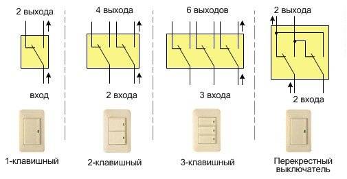
Another type of device that is designed to control electrical appliances from three or more places are cross switches.
Their design is different in that it contains a pair of interconnected contacts, the switching of which occurs simultaneously when a key is pressed. Such products can be made in three- and two-key versions. They are designed, respectively, to control the work of three or two groups of consumers.
Marking on the switch housing
On the part of the switch where the contacts are located, there is usually a special marking indicating the characteristics of the switching product. At a minimum, these are the rated voltage and current, as well as the degree of protection according to IP and the designation of the wire clamps.


If the switch is selected for circuits with fluorescent lamps, then the letters “X” or “AX” must be present in its marking (only “A” is on ordinary ones)
When the light is turned on in fluorescent lamps, a sharp surge of inrush current occurs in the circuit. If LED or incandescent bulbs are used, then this jump is not so big.
Otherwise, the circuit breaker must be designed for such high loads, otherwise there is a risk of burning the contacts in its clamps.
Why is it so important for fluorescent electric lamps to choose special switches
For installation in a bedroom or corridor, a switch with IP03 is quite suitable. For bathrooms, it is better to raise the second digit to 4 or 5. And if the switching product is installed outdoors, then the degree of protection must be at least IP55.
Contact clamps for electrical wires on the switch can be:
- screw with and without pressure plate;
- screwless springs.
The former are more reliable, while the latter greatly simplify the wiring.Moreover, the best option is screw clamps with the addition of a pressure plate. When tightened, they do not destroy the wire core with the tip of the screw.
According to GOST requirements, if the conductor has a cross section of up to 1.5 mm, then it is unacceptable to use a screw clamp to connect it to the switch, in which the end of the screw rotates along the core.
Also in the marking of the switches there are terminal designations:
- "N" - for the zero working conductor.
- "L" - for a conductor with a phase.
- "EARTH" - for zero grounding of the protective conductor.
Plus, usually using "I" and "O" indicates the position of the key in the "ON" and "OFF" modes. There may also be manufacturer logos and product names on the case.
Step-by-step instructions for installing a two-button switch on the hood and lighting in the bathroom
Let's say we need to install a two-gang switch on the hood and lighting in the bathroom. We will assume that all the wires have already been laid and summed up, and the hood and lamp are installed. Our task is to make switching in the box and connect the equipment to the switch.
Let's write out how to do this job with a minimum amount of tools, everything we need is shown in Figure 5.
Tools for the job
List of tools:
- Phillips and slotted screwdrivers.
- Special knife for removing insulation (you can take a regular one);
- Four double WAGO terminals. They will be needed to make connections. Of course, this can be done in other ways (soldering, welding, twisting), but we settled on this option, since it is the simplest, does not require special tools and skills to work with it.Detailed information about WAGO terminals can be found on our website.
- Level.
- Probe (required if wiring is done with monochrome wires).
The algorithm of actions will be as follows:
- We de-energize the wiring in the switchboard - this is a prerequisite for work.
- We carry out switching in the box, connect zero to a common wire from the lamp and the hood, start the phase on the switch, connect the outputs from it to the control wires from the devices. In order not to be mistaken with the purpose of the wires, Figure 6 shows the standard color layout.
Wire colors according to purpose
If the wires are longer, cut off the excess. Using a knife, remove the insulation from them (about 10-15 mm from the edge) and connect them to the WAGO terminals,
- We carry out the connection to the terminals of the switch, for this we cut off the excess and clean the insulation. Now it is necessary to bring the phase to the common input of the switching mechanism, if three single-color wires are connected to the connection point, you will need to find it. To do this, apply voltage to the wiring and touch the wires with the probe one by one. When the search is found, a neon light will light up in the device. After that, turn off the power and continue to work.
We connect the control wires from the hood and the lamp to the outputs of the switching mechanism, the connection order does not matter.
- We install it in a glass (if the device is of a hidden type) or on a prepared place (external version), after which we set the external panel according to the level.
- We connect the hood and the lamp. As a rule, they are provided with a terminal block, if not, double WAGO terminals can be used.
- At the final stage, we check the operation of the assembled circuit. If you follow this algorithm of actions, then there will be no problems.
Note that the connection of the three-gang switch is carried out in a similar way, only 4 wires are required to connect it.
Connecting switches to a socket
How to properly connect a light switch with a switch? For independent development of a lighting connection network with the function of turning the light on and off from different places in the room, the L-conductor from the old lighting line can become a phase. To do this, the input of the first switch is connected to it, and then the wiring is carried out according to one of the described methods.


When installing a new circuit, the phase wire can be led to a nearby outlet or you can find its conductor in the junction box using a special dialing device.

The easiest way to install a walk-through switch is to mount the outlet. This method is practical and efficient in operation. The jumper in this case can be a simple wire with a metal core, which will correspond to the wire section. Cable routing between two switches and junction boxes is carried out in a strobe under a layer of putty (hidden path) or laying in cable ditches.
Why Choose Double Key Switches
There are two popular circuit solutions that have been successfully used for a long time when equipping the electrical system of private houses and apartments.
Option number 1. Installing a DV (two-gang switch) in the bathroom area, if the toilet and bathroom are separated by a wall. Thus, one key controls the light bulb in the toilet, the second - in the bathroom.
Today, this option remains relevant and is actively used in typical housing, where the wiring diagram has not fundamentally changed.
However, to expand control options, instead of a two-gang model, a three-gang switch is sometimes installed if the bathroom is supposed to control not one, but two lamps or groups of lamps.
Mounting a DV instead of two separate devices is preferable from the point of view of saving materials for installation. In addition, it is more convenient to use one switch: by operating the keys, you can turn on and off the light in different rooms with one movement of your hand.
Option number 2. The second common use of a two-button switch is to control a chandelier. The design of the lighting device makes it possible to connect bulbs to two different keys, due to which the light level is adjusted.
If one key controls 2 bulbs, and the second one controls 4, then three lighting modes can be used: muted (2), light (4) and intense (6).

If bright lighting is required for reading, games or a family dinner, then turn on all the bulbs; to create a calm atmosphere for evening relaxation, a subdued light from one lamp is enough
A large number of modern chandeliers, especially those with LEDs, are controlled from a remote control. Multi-colored multi-mode Chinese models are considered especially advanced in this direction. But the option with a switch is still more reliable - the remote control can fail, and electromechanics rarely fail.
With the DV, you can control not only one, but also two lighting fixtures (or groups) installed in the same room. For example, if you connect a chandelier and a pair of sconces to different keys.
So, the two-key functions are quite useful:
- control of multiple light sources;
- segment control of one, but multi-track device (chandelier);
- the ability to adjust the degree of illumination in the room;
- saving of assembly elements.
If you have appreciated the capabilities of a two-key model and want to replace the old one-key with it, then you will have to change the connection scheme and, most likely, you need to start with wiring.
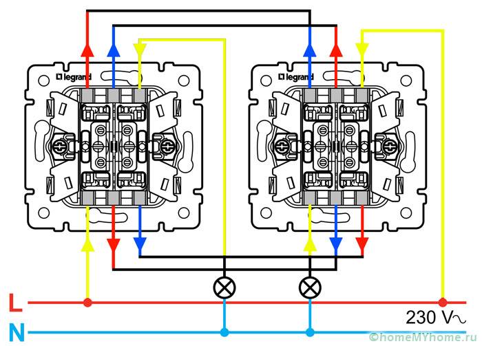
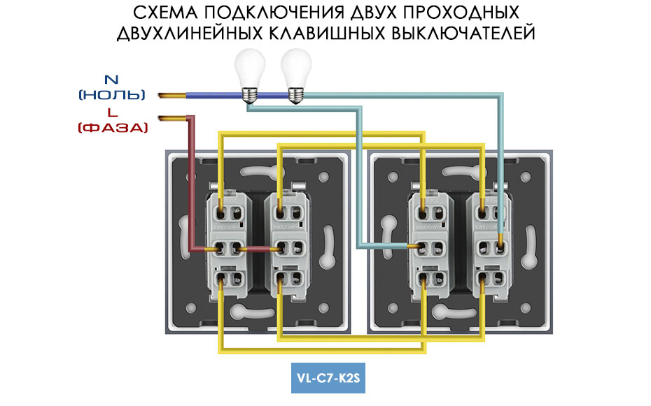
Two-button walk-through switch: control of two groups of luminaires from several places
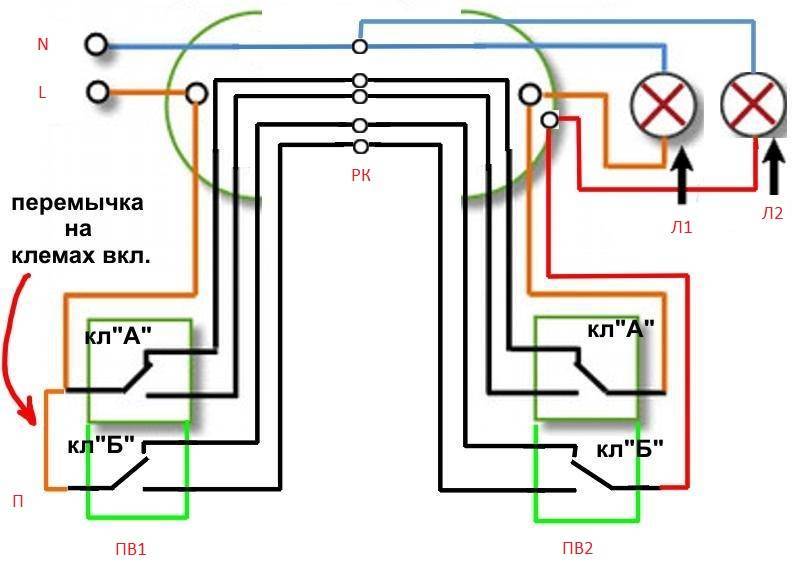
Before proceeding with the solution of the issue of connecting a two-gang pass-through switch, first you need to understand its design. In fact, these are two single pass-through switches installed in one housing. Having realized this nuance, you can easily deal with its connection. It is carried out in the same way as the installation of a conventional single-gang pass-through switch, with the exception of two points.
-
On the first switch, or rather on its two identical parts, the power supply is carried out by one wire (between the two terminals of its different parts are simply connected by a jumper). On the second switch, from which the lighting device is connected, each of the output phases feeds its own lighting device.
-
Number of wires. If, in the case of a single pass-through switch, three wires are laid to each of the devices, then in the case of its two-key analog, five wires will need to be stretched to the first and six to the second. This difference is due to the presence of one common incoming phase on the first switch and two outgoing to different lighting fixtures on the second.
Summing up all of the above, we can conclude that by operating with walk-through and cross switches with a different number of keys, you can build quite complex circuits that allow you to control lighting from the required number of places - by and large, there can be many of them. Another thing is the expediency of such schemes. As a rule, in everyday life everything is limited to a maximum of three control points. Rarely, but still there is a need to turn on and off the light from four or even five places. But that's not the point - the point is that having mastered a simple one-key pass-through switch and the principle of its installation, you can easily operate these devices and create any circuits that are convenient for you.
Author of the article Alexander Kulikov


