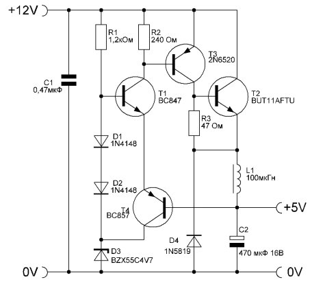
- Wiring diagram based on LM2940CT-12.0
- What you need to connect
- Adjusting the Inertial Image Stabilizer for the Camera
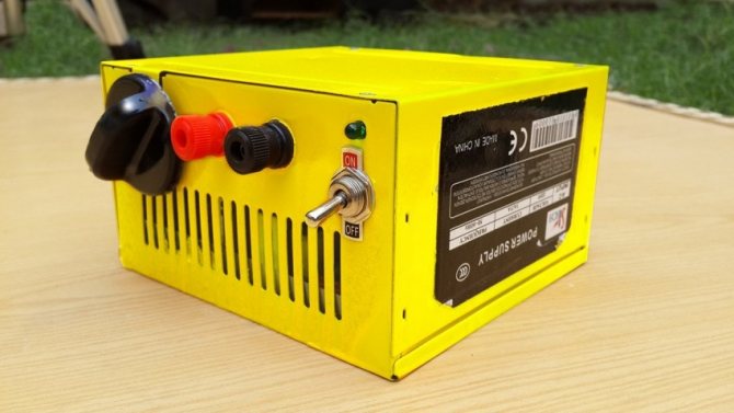
- DIY adjustable power supply
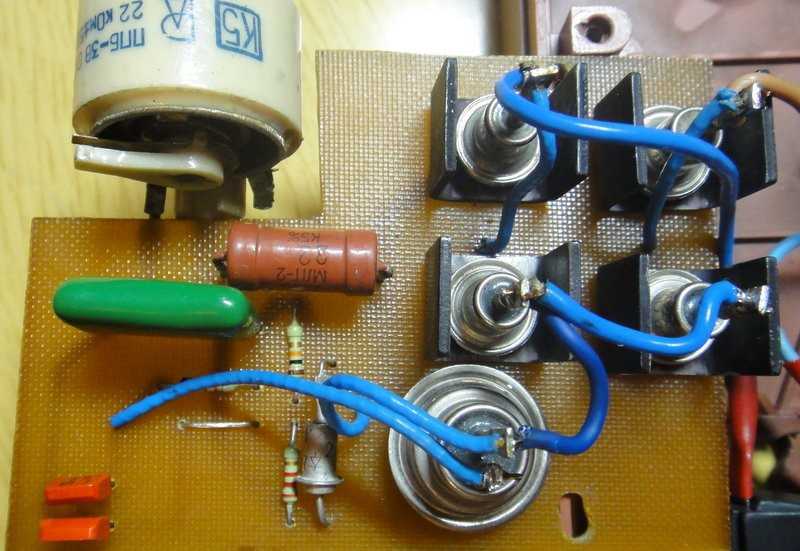
- The principle of operation and homemade test
- Power supply indicator
- Electromechanical (servo) devices
- How to use the inertial stabilizer
- inverter technology
- DIY power supply photo
- Step by step setup
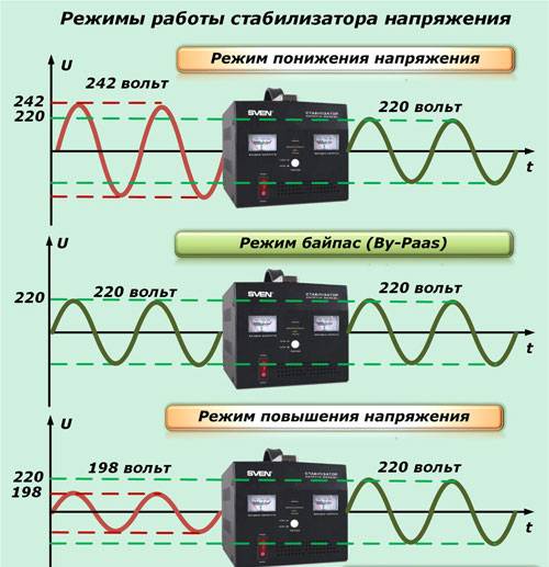
- Types of voltage stabilizers
- Automatic stabilizers "Ligao 220 V"
- Subtleties of adjustment
- Varieties of 12V stabilizers
- Classic Stabilizer
- integral stabilizer
- ↑ Program
- AC Models
- Features of the assembly of the device for equalizing voltage
- Which voltage regulator is better: relay or triac?
- Inverter stabilizers
Wiring diagram based on LM2940CT-12.0
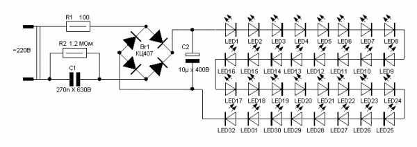
The body of the stabilizer can be made from almost any material except wood. When using more than ten LEDs, it is recommended to attach an aluminum heatsink to the stabilizer.
Maybe someone has tried it and will say that you can easily do without unnecessary troubles by directly connecting the LEDs. But in this case, the latter will be in unfavorable conditions most of the time, therefore they will not last long or even burn out.But tuning expensive cars results in a fairly large amount.
And about the described schemes, their main advantage is simplicity. It does not require special skills and abilities to make. However, if the circuit is too complicated, then it becomes not rational to assemble it with your own hands.
What you need to connect
In addition to the stabilizer itself, you will need a number of additional materials:
three-core cable VVGnG-Ls
The cross section of the wire must be exactly the same as on your input cable, which comes to the switch or main input machine. Since the entire load of the house will go through it.
three-position switch
This switch, unlike simple ones, has three states:
123
You can also use a conventional modular machine, but with such a scheme, if you need to disconnect from the stabilizer, you will have to completely de-energize the whole house each time and switch the wires.
Of course, there is a bypass or transit mode, but in order to switch to it, you need to follow a strict sequence. More on this will be discussed below.
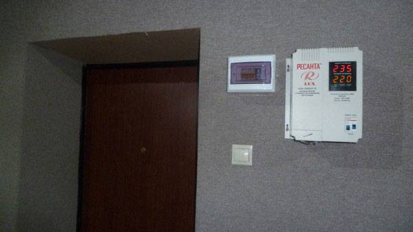
With this switch, you completely cut off the unit with one movement, and the house remains with the light directly.
PUGV wire of different colors
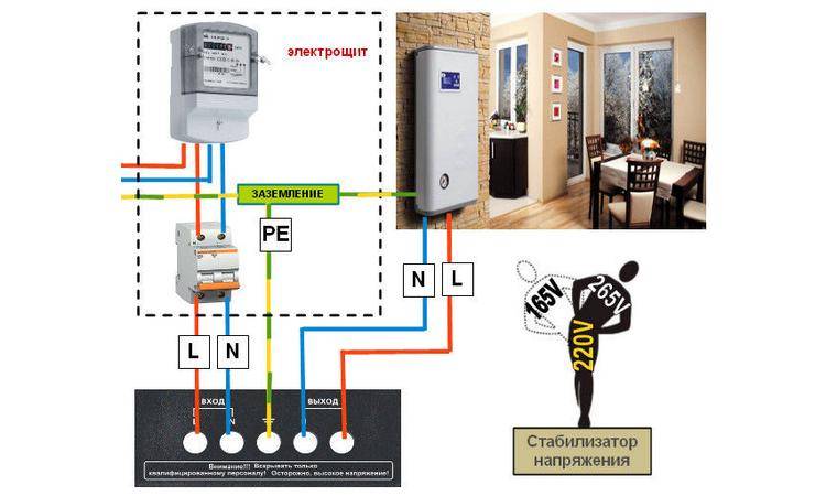
You must clearly understand that the voltage regulator is installed strictly before the electric meter, and not after it.
No energy supply organization will allow you to connect differently, no matter how you prove that by doing so, in addition to the electrical equipment in the house, you want to protect the meter itself.
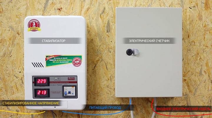
The stabilizer has its own idling and also consumes electricity, even when operating without load (up to 30 W / h and above). And this energy must be taken into account and calculated.
The second important point is that it is highly desirable that in the circuit to the point of connection of the stabilization device there should be either an RCD or a differential automatic device.
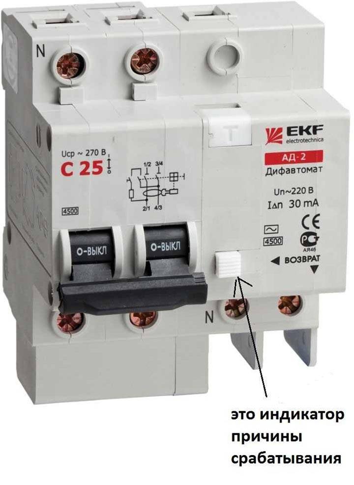
This is recommended by all manufacturers of popular brands Resanta, Sven, Leader, Shtil, etc.
It can be an introductory differential machine for the whole house, it doesn’t matter. The main thing is that the equipment itself is protected from current leakage.
A breakdown of the transformer windings on the case is not such a rare thing.
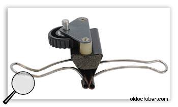
Adjusting the Inertial Image Stabilizer for the Camera

If you are using weights, the position of the center of gravity of which cannot be changed (as in the photo), then you can adjust the horizon by turning the vertical bar at a small angle in its attachment point. Before adjustment, one of the screws is loosened, and the second is not fully tightened. After that, the bar is set to the desired position, and both screws are tightened.

If the camera does not have an electronic level indicator, an external bubble level can be used to adjust the horizontal position of the camera.
If you refuse to install a quick-release platform, and use a standard photo screw, then such a stabilizer can be made in a couple of hours.
And here is an idea how you can raise the photo screw from the flash above the horizontal bar. Long time ago used this solution here>>>
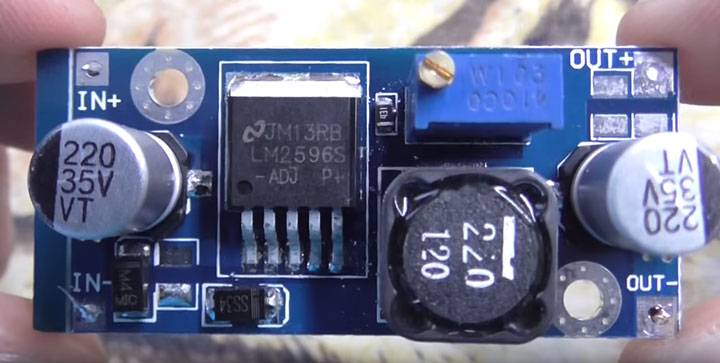
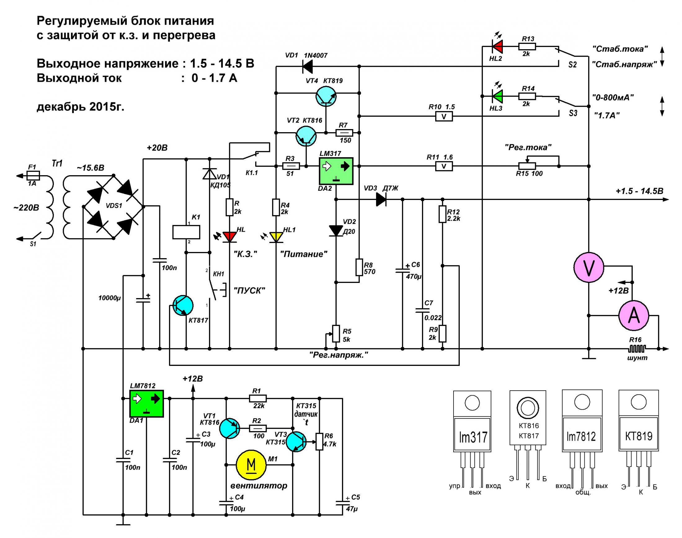
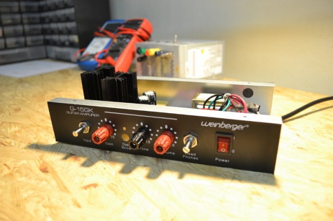
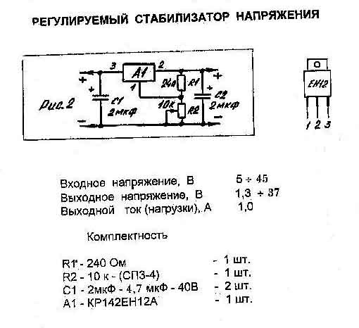
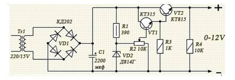
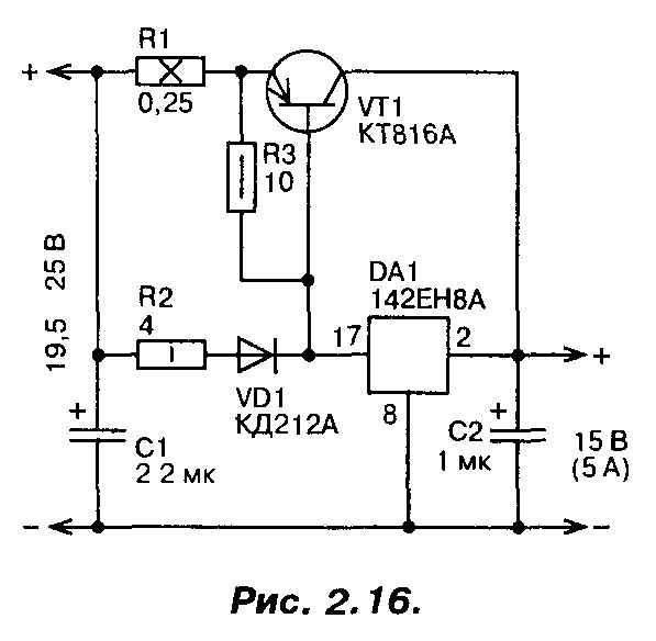
DIY adjustable power supply
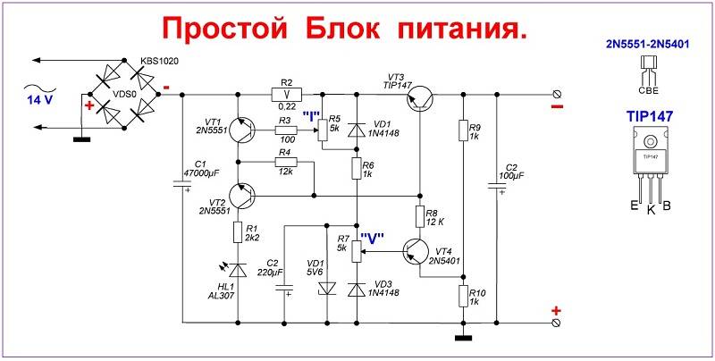
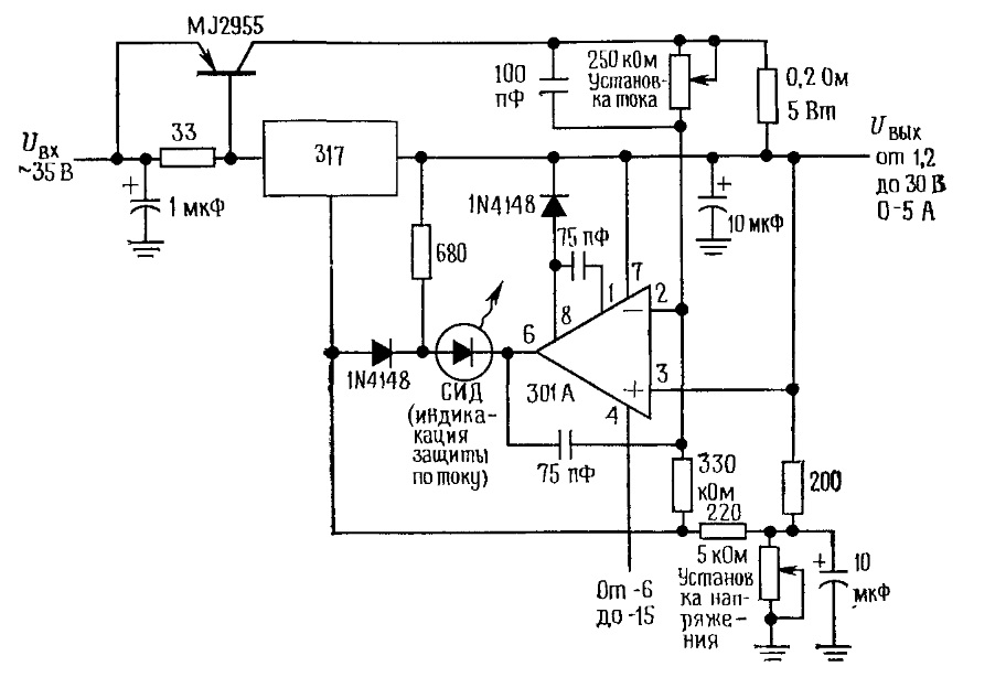
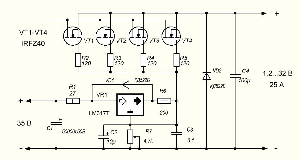
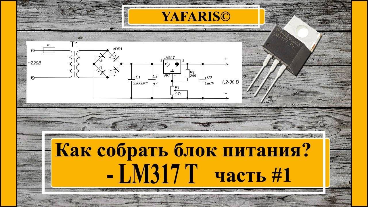
A power supply is a necessary thing for every radio amateur, because to power electronic homemade products you need an adjustable power supply with a stabilized output voltage from 1.2 to 30 volts and a current of up to 10A, as well as built-in short circuit protection. The circuit shown in this figure is built from the minimum number of available and inexpensive parts.
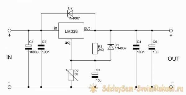
 Scheme of an adjustable power supply on the LM317 stabilizer with short circuit protection
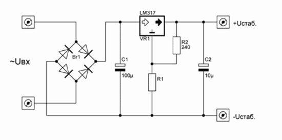
The LM317 is an adjustable voltage regulator with built-in short circuit protection. The LM317 voltage regulator is designed for a current of no more than 1.5A, so a powerful MJE13009 transistor is added to the circuit, capable of passing a really large current up to 10A, according to the datasheet, a maximum of 12A. When the knob of the variable resistor P1 is rotated by 5K, the voltage at the output of the power supply changes.
There are also two shunt resistors R1 and R2 with a resistance of 200 ohms, through which the microcircuit determines the output voltage and compares it with the input voltage. Resistor R3 at 10K discharges capacitor C1 after the power supply is turned off. The circuit is powered by a voltage of 12 to 35 volts. The current strength will depend on the power of the transformer or switching power supply.
And I drew this diagram at the request of novice radio amateurs who assemble circuits by surface mounting.
 Scheme of an adjustable power supply with short circuit protection on the LM317
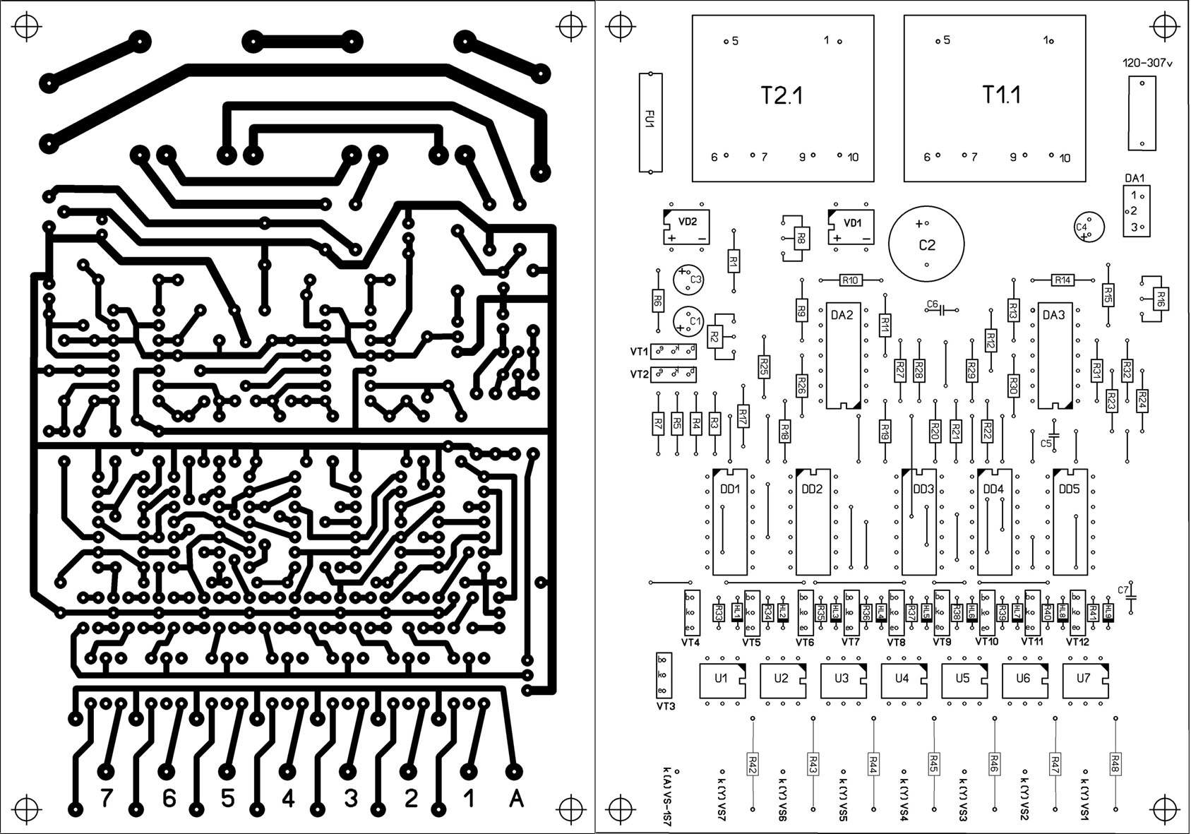
Assembly is desirable to perform on a printed circuit board, so it will be nice and neat.
 The printed circuit board of the regulated power supply on the voltage regulator LM317
The printed circuit board is made for imported transistors, so if you need to install a Soviet one, the transistor will have to be deployed and connected with wires. The MJE13009 transistor can be replaced with MJE13007 from the Soviet KT805, KT808, KT819 and other n-p-n structure transistors, it all depends on the current you need. It is desirable to strengthen the power tracks of the printed circuit board with solder or thin copper wire.The LM317 voltage regulator and the transistor must be installed on a radiator with an area sufficient for cooling, a good option is, of course, a radiator from a computer processor.
It is advisable to screw a diode bridge there as well. Don't forget to insulate the LM317 from the heatsink with a plastic washer and a heat conductive gasket or a big boom will occur. Almost any diode bridge can be installed for a current of at least 10A. Personally, I put the GBJ2510 at 25A with double the power margin, it will be twice as cold and more reliable.

And now the most interesting ... Testing the power supply for strength.
I connected the voltage regulator to a power source with a voltage of 32 volts and an output current of 10A. Without load, the voltage drop at the output of the regulator is only 3V. Then I connected two H4 55W 12V halogen lamps connected in series, connected the filaments of the lamps together to create a maximum load, as a result, 220 watts were obtained. The voltage dipped by 7V, the nominal voltage of the power supply was 32V. The current consumed by four filaments of halogen lamps was 9A.

The radiator began to heat up quickly, after 5 minutes the temperature rose to 65C°. Therefore, when removing heavy loads, I recommend installing a fan. You can connect it according to this scheme. You can not install a diode bridge and a capacitor, but connect the L7812CV voltage regulator directly to capacitor C1 of an adjustable power supply.
 Scheme of connecting the fan to the power supply
What will happen to the power supply in case of a short circuit?
In the event of a short circuit, the voltage at the output of the regulator drops to 1 volt, and the current strength is equal to the current strength of the power source in my case 10A.In this state, with good cooling, the unit can stay for a long time, after the short circuit is eliminated, the voltage is automatically restored to the limit set by the variable resistor P1. During the 10 minute test in short circuit mode, not a single part of the power supply was damaged.
Radio components for assembling an adjustable power supply on the LM317
- Voltage regulator LM317
- Diode bridge GBJ2501, 2502, 2504, 2506, 2508, 2510 and other similar ones rated for a current of at least 10A
- Capacitor C1 4700mf 50V
- Resistors R1, R2 200 ohm, R3 10K all 0.25W resistors
- Variable resistor P1 5K
- Transistor MJE13007, MJE13009, KT805, KT808, KT819 and other n-p-n structures
Friends, I wish you good luck and good mood! See you in new articles!
I recommend watching a video on how to make an adjustable power supply with your own hands
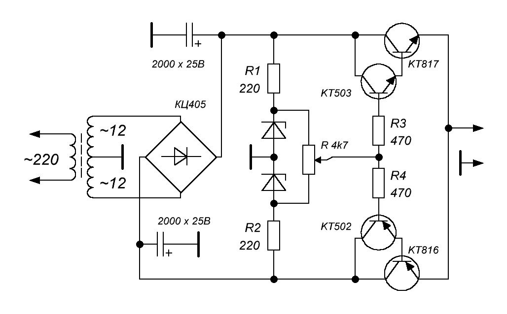
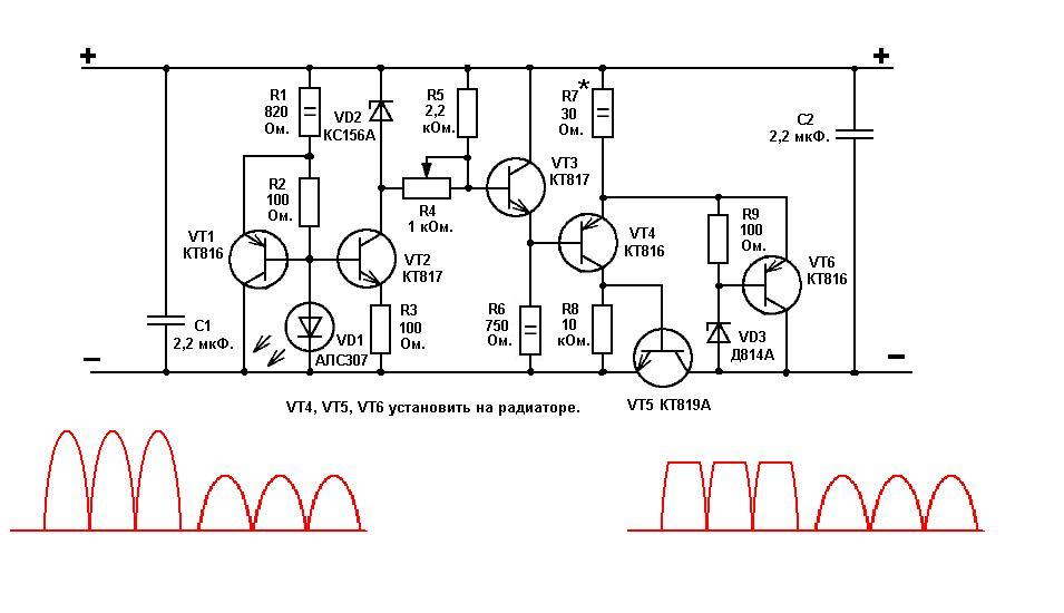
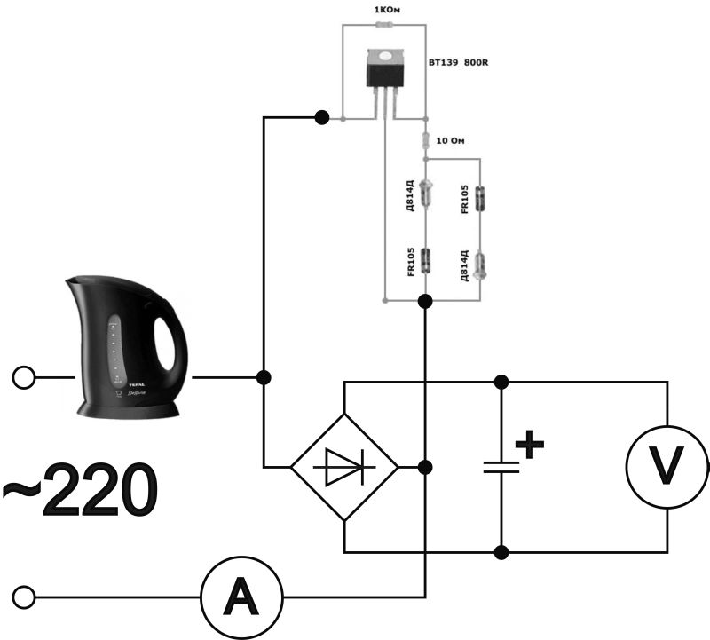
The principle of operation and homemade test
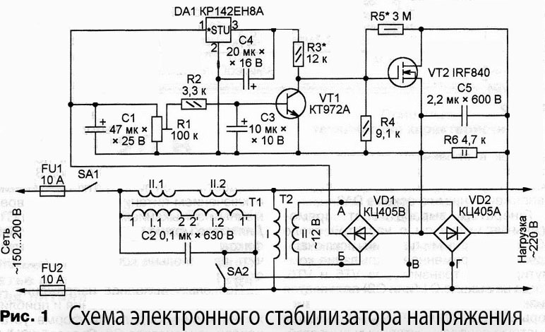
The regulating element of the electronic stabilization circuit is a powerful field-effect transistor of the IRF840 type.
The voltage for processing (220-250V) passes through the primary winding of the power transformer, is rectified by the VD1 diode bridge and goes to the drain of the IRF840 transistor. The source of the same component is connected to the negative potential of the diode bridge.

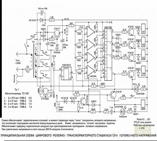
Schematic diagram of a high power stabilizing unit (up to 2 kW), on the basis of which several devices were assembled and successfully used. The circuit showed the optimal level of stabilization at the specified load, but not higher
The part of the circuit where one of the two secondary windings of the transformer is connected is formed by a diode rectifier (VD2), a potentiometer (R5) and other elements of the electronic regulator. This part of the circuit generates a control signal that is fed to the gate of the IRF840 field effect transistor.
In the event of an increase in the supply voltage, the control signal lowers the gate voltage of the field-effect transistor, which leads to the closing of the key.
Accordingly, on the load connection contacts (XT3, XT4), the possible increase in voltage is limited. The circuit works in reverse in case of a decrease in the mains voltage.
Setting up the device is not particularly difficult. Here you need a conventional incandescent lamp (200-250 W), which should be connected to the output terminals of the device (X3, X4). Further, by rotating the potentiometer (R5), the voltage at the marked terminals is brought to a level of 220-225 volts.
Turn off the stabilizer, turn off the incandescent lamp and turn on the device already with a full load (not higher than 2 kW).
After 15-20 minutes of operation, the device is turned off again and the temperature of the radiator of the key transistor (IRF840) is monitored. If the heating of the radiator is significant (more than 75º), a more powerful heat sink radiator should be selected.
Power supply indicator
I conducted an audit, found a couple of simple M68501 arrowheads for this PSU. I spent half a day creating a screen for it, but still drew it and fine-tuned it to the required output voltages.
The resistance of the indicator head used and the applied resistor are indicated in the attached file on the indicator.I spread the front panel of the block, if anyone needs a case from an ATX power supply to remake, it will be easier to rearrange the inscriptions and add something than to create from scratch. If other voltages are required, the scale can simply be recalibrated, this will be easier. Here is the finished view of the regulated power supply:
Film - self-adhesive type "bamboo". The indicator has a green backlight. The red Attention LED indicates that the overload protection has been activated.
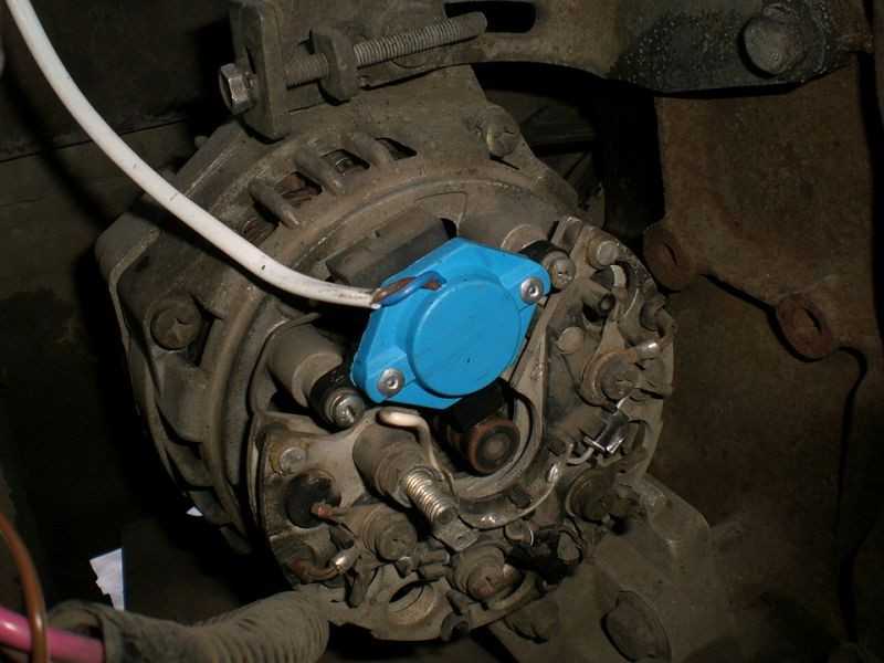
Electromechanical (servo) devices
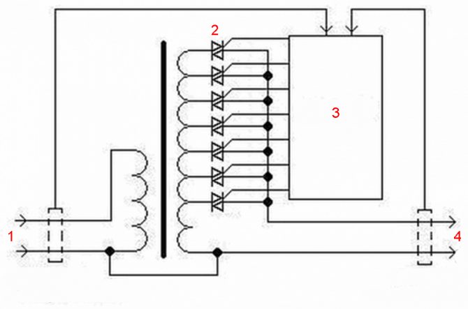
The mains voltage is adjusted by means of a slider that moves along the winding. At the same time, a different number of turns is involved. We all studied at school, and some may have dealt with a rheostat in physics lessons.
An electromechanical voltage stabilizer works according to this similar principle. Only the movement of the slider is not carried out manually, but with the help of an electric motor called a servo drive. Knowing the device of these devices is simply necessary if you want to make a 220V voltage regulator with your own hands according to the scheme.
Electromechanical devices are highly reliable and provide smooth voltage regulation. Characteristic advantages:
- Stabilizers work under any load.
- The resource is significantly greater than that of other analogues.
- Affordable cost (half lower than electronic devices)
Unfortunately, with all the advantages, there are also disadvantages:
- Due to the mechanical device, the response delay is very noticeable.
- Such devices use carbon contacts, which are subject to natural wear over time.
- The presence of noise during operation, although it is almost inaudible.
- Small operating range 140-260 V.
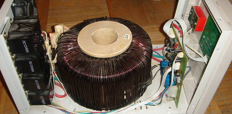
It is worth noting that, unlike the 220V inverter voltage stabilizer (you can make it yourself according to the scheme, despite the apparent difficulties), there is still a transformer here. As for the principle of operation, the voltage analysis is carried out by the electronic control unit. If he notices significant deviations from the nominal value, he sends a command to move the slider.
The current is regulated by connecting more turns of the transformer. In the event that the device does not have time to respond in a timely manner to an excessive excess of voltage, a relay is provided in the stabilizer device.
How to use the inertial stabilizer
As it turned out, using an inertial stabilizer is much easier than a traditional steadicam. The rigid inertial stabilizer is always instantly ready for operation, due to the absence of damped oscillations characteristic of pendulum-type steadicams.
When accelerating, it is enough for the operator to squeeze the handle of the device harder, and loosen the grip as soon as the speed of movement stabilizes and the trajectory becomes straight.
The weight of the structure balancing in the hand makes it easy to feel the position of the camera relative to the horizon through tactile sensations. It is to improve tactile sensations that the handle is removed from the center of gravity of the system at a greater distance than in professional video cameras.
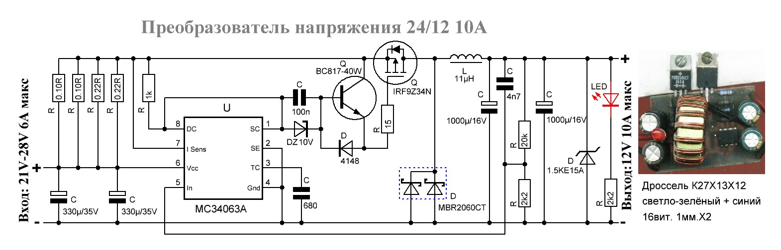
inverter technology
A distinctive feature of such devices is the absence of a transformer in the design of the device. However, voltage regulation is carried out electronically, and therefore it belongs to the previous type, but is, as it were, a separate class.
If there is a desire to make a home-made voltage stabilizer 220V, the circuit of which is not difficult to get, then it is better to choose inverter technology. After all, the very principle of work is interesting here. Inverter stabilizers are equipped with double filters, which minimizes voltage deviations from the nominal value within 0.5%. The current entering the device is converted into a constant voltage, passes through the entire device, and before exiting again takes its previous form.
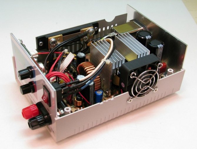
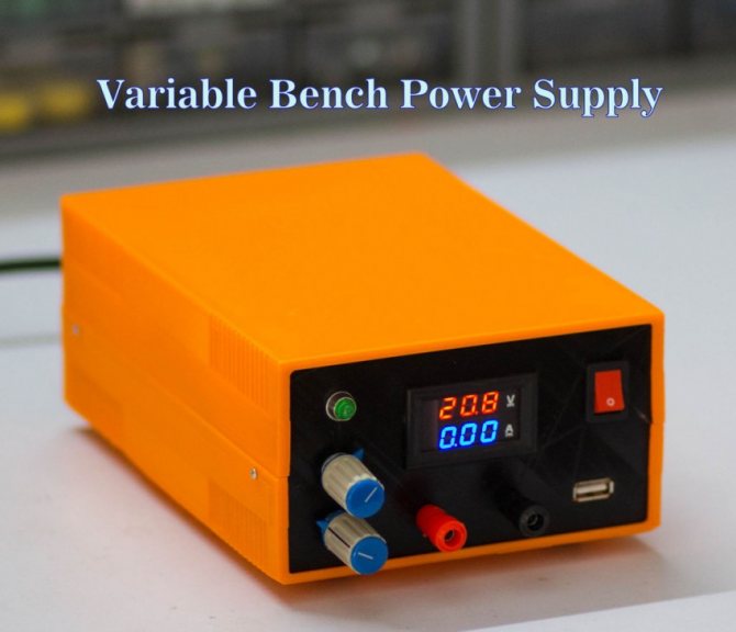
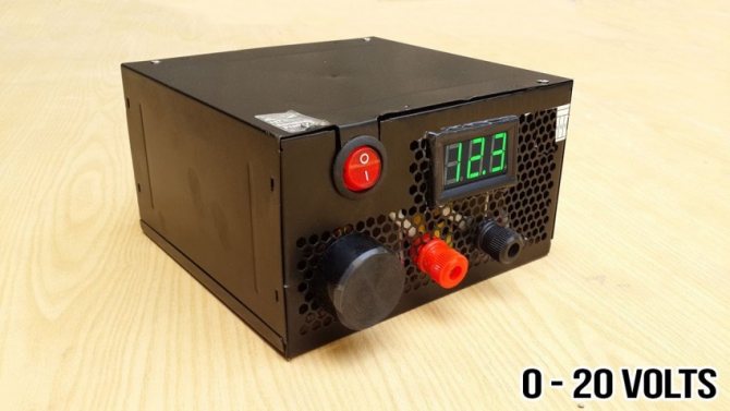
DIY power supply photo


We also recommend viewing:
- DIY fan
- Feeding with your own hands
- Sliding gates with their own hands
- DIY computer repair
- Do-it-yourself woodworking machine
- Do-it-yourself tabletop
- Do-it-yourself bars
- DIY lamp
- DIY boiler
- Do-it-yourself air conditioner installation
- DIY heating
- DIY water filter
- How to make a knife with your own hands
- DIY signal amplifier
- DIY TV repair
- DIY battery charger
- DIY spot welding
- Do-it-yourself smoke generator
- DIY metal detector
- Do-it-yourself washing machine repair
- Do-it-yourself refrigerator repair
- DIY antenna
- DIY bicycle repair
- Do-it-yourself welding machine
- Cold forging with your own hands
- Do-it-yourself pipe bender
- DIY chimney
- DIY grounding
- DIY rack
- DIY lamp
- DIY blinds
- DIY LED strip
- Do-it-yourself level
- Do-it-yourself timing belt replacement
- DIY boat
- How to make a pump with your own hands
- DIY compressor
- DIY sound amplifier
- DIY aquarium
- DIY drilling machine
Step by step setup
A do-it-yourself laboratory power supply made with your own hands needs to be turned on step by step. The initial start-up takes place with the LM301 and transistors disabled. Next, the function regulating the voltage through the P3 regulator is checked.
If the voltage is regulated well, then transistors are included in the circuit. Their work will then be good when several resistances R7, R8 begin to balance the emitter circuit. We need such resistors so that their resistance is at the lowest possible level. In this case, the current should be enough, otherwise in T1 and T2 its values \u200b\u200bwill differ.
Also, the connection of capacitor C2 may be incorrect. After inspecting and correcting installation defects, it is possible to supply power to the 7th leg of the LM301. This can be done from the output of the power supply.
At the last stages, P1 is configured so that it can operate at the maximum operating current of the PSU. A laboratory power supply with voltage regulation is not so difficult to adjust. In this case, it is better to once again double-check the installation of parts than to get a short circuit with the subsequent replacement of elements.
Types of voltage stabilizers
Depending on the load power in the network and other operating conditions, various models of stabilizers are used:
Ferroresonant stabilizers are considered the simplest, they use the principle of magnetic resonance. The circuit includes only two chokes and a capacitor. Outwardly, it looks like a conventional transformer with primary and secondary windings on chokes.Such stabilizers have a large weight and dimensions, so they are almost never used for household equipment. Due to the high speed, these devices are used for medical equipment;
Schematic diagram of a ferroresonant voltage regulator
Servo-driven stabilizers provide voltage regulation by an autotransformer, the rheostat of which is controlled by a servo drive that receives signals from a voltage control sensor. Electromechanical models can work with large loads, but have a low response speed. The relay voltage stabilizer has a sectional design of the secondary winding, voltage stabilization is carried out by a group of relays, the signals for closing and opening the contacts of which come from the control board. Thus, the necessary sections of the secondary winding are connected to maintain the output voltage within the specified values. The adjustment speed is fast, but the voltage setting accuracy is not high;
An example of assembling a relay voltage stabilizer
Electronic stabilizers have a similar principle as relay stabilizers, but instead of relays, thyristors, triacs or field-effect transistors are used to rectify the corresponding power, depending on the load current. This significantly increases the switching speed of the secondary winding sections. There are variants of circuits without a transformer unit, all nodes are made on semiconductor elements;
A variant of the electronic stabilizer circuit
Double conversion voltage stabilizers regulate according to the inverter principle. These models convert AC voltage to DC, then back to AC voltage, 220V is formed at the output of the converter.
Option inverter voltage regulator circuit
The stabilizer circuit does not convert the mains voltage. The DC-to-AC inverter generates 220V AC at the output at any input voltage. Such stabilizers combine high response speed and voltage setting accuracy, but have a high price compared to previously considered options.
Automatic stabilizers "Ligao 220 V"
For alarm systems, it is in demand from a voltage stabilizer 220V. Its circuit is built on the work of thyristors. These elements can be used exclusively in semiconductor circuits. To date, there are quite a few types of thyristors. According to the degree of security, they are divided into static and dynamic. The first type is used with sources of electricity of various capacities. In turn, dynamic thyristors have their own limit.
If we talk about a voltage stabilizer (the diagram is shown below), then it has an active element. To a greater extent, it is intended for the normal functioning of the regulator. It is a set of contacts that are able to connect. This is necessary in order to increase or decrease the limiting frequency in the system. In other models of thyristors, there may be several. They are installed with each other using cathodes. As a result, the efficiency of the device can be significantly improved.
Subtleties of adjustment
The need for a voltage regulator will be under the following conditions:
- Adjustment of alternating, and constant tension is necessary.
- The ability to regulate the voltage in the load.
Each listed item defines its own set of radio components in the circuit.But the device of the simplest regulator is based on a variable resistor. When adjusting the AC voltage, no distortion is created. With the help of variable resistance, it is also possible to adjust the direct current.


In order for the voltage and current load to be a given parameter, stabilizers are used. The output voltage is checked against the correct value, and if small predetermined changes occur, the regulator automatically recovers.

You can find many step-by-step instructions on how to make a voltage regulator. But the simplest and most understandable option is considered to be a device on integrated circuits. The convenience of products allows you to power LEDs and other lighting systems in the car. A buck converter is needed for the mains regulator, and a rectifier should be connected to the input.

Very often, the load can have different parameters, so for such cases, special voltage stabilizers are indispensable. Their work can be carried out in several modes.
For all electronic type devices, it is important to obtain a stable voltage. They have non-linear components built into the electrical circuit.

There is a voltage regulator based on a thyristor. This is a very powerful semiconductor, which is used in high power converters. Due to the specific control, it is used for switching "changes".

Varieties of 12V stabilizers
Such devices can be assembled on transistors or on integrated circuits. Their task is to ensure the value of the rated voltage Unom within the required limits, despite fluctuations in the input parameters. The most popular schemes are:
- linear;
- impulse.
The linear stabilization circuit is a simple voltage divider. Its work lies in the fact that when Uin is applied to one "shoulder", the resistance changes on the other "shoulder". This keeps Uout within the given limits.
Important! With such a scheme, with a large spread of values between input and output voltages there is a drop in efficiency (a certain amount of energy is converted into heat), and the use of heat sinks is required. Pulse stabilization is controlled by a PWM controller. He, controlling the key, regulates the duration of the current pulses
The controller compares the value of the reference (set) voltage with the output voltage. The input voltage is supplied to the key, which, opening and closing, supplies the received pulses through a filter (capacitance or inductor) to the load
He, controlling the key, regulates the duration of the current pulses. The controller compares the value of the reference (set) voltage with the output voltage. The input voltage is supplied to the key, which, opening and closing, supplies the received pulses through a filter (capacitance or inductor) to the load
Pulse stabilization is controlled by a PWM controller. He, controlling the key, regulates the duration of the current pulses. The controller compares the value of the reference (set) voltage with the output voltage. The input voltage is applied to the key, which, opening and closing, supplies the received pulses through a filter (capacitance or inductor) to the load.
Note. Switching voltage stabilizers (SN) have a high efficiency, require less heat removal, but electrical impulses interfere with electronic devices during operation.Self-assembly of such circuits has significant difficulties.
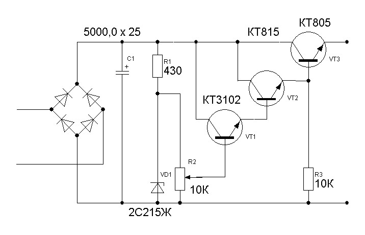
Classic Stabilizer
Such a device includes: a transformer, a rectifier, filters and a stabilization unit. Stabilization is usually carried out using zener diodes and transistors.
The main work is performed by the zener diode. This is a kind of diode that is connected to the circuit in reverse polarity. Its operating mode is breakdown mode. The principle of operation of the classic CH:
- when Uin < 12 V is applied to the zener diode, the element is in the closed state;
- when Uin > 12 V enters the element, it opens and keeps the declared voltage constant.
Attention! The supply of Uin exceeding the maximum values specified for a certain type of zener diode leads to its failure. Scheme of a classic linear CH. Scheme of a classic linear CH
Scheme of a classic linear CH
integral stabilizer
All structural elements of such devices are located on a silicon crystal, the assembly is enclosed in an integrated circuit (IC) package. They are assembled on the basis of two types of ICs: semiconductor and hybrid-film. The former have solid-state components, while the latter are made of films.
The main thing! Such parts have only three outputs: input, output and adjustment. Such a microcircuit can produce a stable voltage of 12 V at an interval of Uin \u003d 26-30 V and a current of up to 1 A without additional strapping.
SN circuit on IC
↑ Program
The program is written in C language (mikroC PRO for PIC), divided into blocks and provided with comments.The program uses direct measurement of AC voltage by a microcontroller, which made it possible to simplify the circuit. Microprocessor applied PIC16F676. Program block zero waits for a falling zero crossing to occur. This edge either measures the AC voltage or starts switching the relay. Program block izm_U measures the amplitudes of the negative and positive half-cycles
In the main program, the measurement results are processed and, if necessary, a command is given to switch the relay. Separate programs for switching on and off are written for each group of relays, taking into account the necessary delays R2on, R2off, R1on and R1off. The 5th bit of port C is used in the program to send a clock pulse to the oscilloscope so that you can look at the results of the experiment.
AC Models
The alternating current regulator is different in that the thyristors in it are used only of the triode type. In turn, transistors are commonly used field-type. Capacitors in the circuit are used only for stabilization. It is possible, but rare, to meet high-frequency filters in devices of this type. High temperature problems in models are solved by a pulse converter. It is installed in the system behind the modulator. Low-pass filters are used in regulators with power up to 5 V. The cathode control in the device is carried out by suppressing the input voltage.
Stabilization of the current in the network occurs smoothly. In order to cope with high loads, reverse zener diodes are used in some cases. They are connected by transistors using a choke.In this case, the current regulator must be able to withstand a maximum load of 7 A. In this case, the limiting resistance level in the system must not exceed 9 ohms. In this case, you can hope for a fast conversion process.
Features of the assembly of the device for equalizing voltage
The microcircuit of the current-stabilizing device is mounted on a heat sink, for which an aluminum plate is suitable. Its area should not be less than 15 square meters. cm.
A heat sink with a cooling surface is also necessary for triacs. For all 7 elements, one heat sink with an area of at least 16 square meters is sufficient. dm.
In order for the AC voltage converter manufactured by us to work, you need a microcontroller. The KR1554LP5 chip does an excellent job with its role.
You already know that 9 flashing diodes can be found in the circuit. All of them are located on it so that they fall into the holes that are on the front panel of the device. And if the body of the stabilizer does not allow their location, as in the diagram, then you can modify it so that the LEDs go to the side that is convenient for you.
Now you know how to make a voltage regulator for 220 volts. And if you have already had to do something similar before, then this work will not be difficult for you. As a result, you can save several thousand rubles on the purchase of an industrial stabilizer.
Which voltage regulator is better: relay or triac?
Triac-type devices are characterized by small housing sizes, and the level of compactness of such devices is quite comparable with electromechanical and relay-type models.The average cost of a triac device compared to high-quality relay similar devices is almost two to three times higher.
Relay stabilizer “Resanta 10000/1-ts”
Despite the excellent switching speed and the presence of a significant gap on the input voltages, any relay device is noisy in operation and is characterized by poor accuracy.
Among other things, all relay stabilizers have some restrictions on the power level, which is due to the inability of the contacts to switch very high currents.
Thinking about whether to connect a day-night meter? Read the article about whether double tariffs are beneficial.
The procedure for assembling an LED flashlight with your own hands is described in this article.
The most promising type of electronic stabilizers is currently represented by modern devices that operate under conditions of double conversion of the mains voltage.
In addition to the high cost, such devices do not have serious drawbacks. That is why when choosing a stabilizing device, if the cost is not critical, it is advisable to give preference to devices that are fully assembled using high-quality semiconductors.
Inverter stabilizers
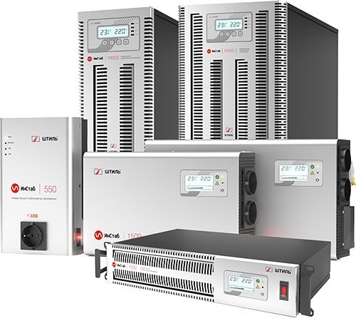 Modern inverter stabilizers Calm series "Instab" This is the "youngest" type of stabilizers - mass production began in the late 2000s. Innovative design and features not available in other topologies make these devices a breakthrough in electrical energy stabilization.
Device and principle of operation.
The principle of operation of these devices is similar to on-line UPS and is built on the basis of advanced technology of double energy conversion. First, the rectifier converts the input AC voltage to DC, which is then accumulated in the intermediate capacitors and fed to the inverter, which converts back into a stabilized AC output voltage. Inverter stabilizers are fundamentally different from relay, thyristor and electromechanical in internal structure. In particular, they lack an autotransformer and any moving elements, including relays. Accordingly, double conversion stabilizers are free from the disadvantages inherent in transformer models.
Advantages.
The operation algorithm of this group of devices eliminates the transmission of any external disturbance to the output, which provides complete protection against most power supply problems and guarantees that the load is powered by an ideal sinusoidal voltage with a value as close as possible to the nominal value (±2% accuracy). In addition, the inverter topology eliminates all the shortcomings characteristic of other principles of electric energy stabilization and provides models based on it with unique speed - the stabilizer responds to input signal changes instantly, without time delays (0 ms)!
Other important advantages of inverter stabilizers:
- the widest limits of the operating mains voltage - from 90 to 310 V, while the ideal sinusoidal shape of the output signal is maintained throughout the specified range;
- continuous stepless voltage regulation - eliminates a number of unpleasant effects associated with switching stabilization thresholds in electronic (relay and semiconductor) models;
- the absence of an autotransformer and movable mechanical contacts - increases the service life and reduces the weight of the product;
- the presence of input and output high-frequency filters - effectively suppress the resulting interference (not present in all models, typical in particular for the products of Shtil Group, a leading manufacturer of inverter stabilizers).
A logical question arises - are there any disadvantages to inverter devices? The only and at the same time controversial drawback is the higher price. But given the technical requirements of modern household appliances and at the same time the continuing trend of mains voltage drops, inverter stabilizers today are the most cost-effective option for permanent use both in private houses and country cottages, and at industrial facilities. They guarantee the stable, correct functioning of expensive household appliances and sensitive electronic devices, regardless of the quality of the power supply.
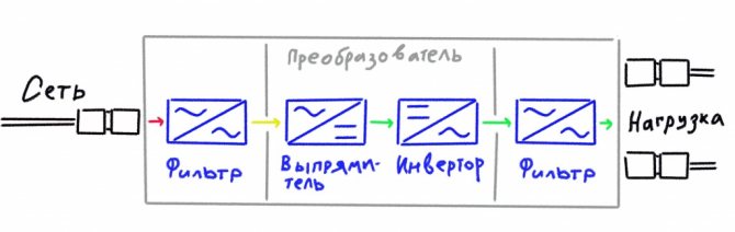
Figure 4 - Diagram of an inverter voltage regulator
Read more on this topic below:
Inverter voltage stabilizers "Calm". The lineup.


Very interesting and informative article!