- Screed
- Design Features
- We calculate the circulation pump
- Underfloor heating connection diagrams
- Directly from the boiler
- From a three-way valve
- From the pumping and mixing unit
- From the radiator
- Why is it better to use a pipe with an outer diameter of 16 mm?
- What affects the operation of a warm water floor
- Connection to an individual heating boiler
- Heat distribution: features
- Laying technology of electric underfloor heating system
- Surface preparation
- markup
- Mounting. Walkthrough
- Important points!
- Types of electrical cables
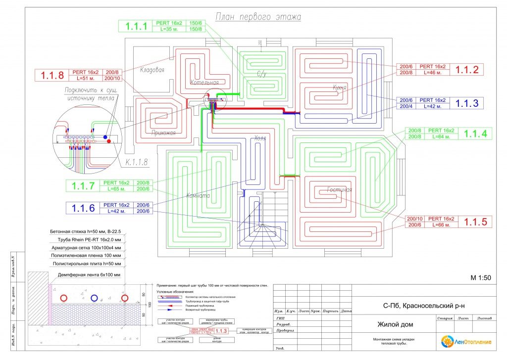
Screed
IMPORTANT: the top layer of the screed is poured only when the contour is filled. But before that, metal pipes are grounded and covered with a thick plastic film.
This is an important condition to prevent corrosion due to electrochemical interactions of materials.
The issue of reinforcement can be solved in two ways. The first is to put a masonry mesh on top of the pipe. But with this option, cracks may appear due to shrinkage.
Another way is dispersed fiber reinforcement. When pouring water heated floors, steel fiber is best suited. Added in the amount of 1 kg/m3 of solution, it will be evenly distributed throughout the volume and qualitatively increase the strength of the hardened concrete.Polypropylene fiber is much less suitable for the top layer of the screed, because the strength characteristics of steel and polypropylene do not even compete with each other.
Beacons are installed and the solution is kneaded according to the above recipe. The thickness of the screed must be at least 4 cm above the surface of the pipe. Considering that the ø of the pipe is 16 mm, the total thickness will reach 6 cm. The maturation time of such a layer of cement screed is 1.5 months
IMPORTANT: It is unacceptable to speed up the process including floor heating! This is a complex chemical reaction of the formation of "cement stone", which occurs in the presence of water. Heat will cause it to evaporate
You can accelerate the maturation of the screed by including special additives in the recipe. Some of them cause complete hydration of the cement after 7 days. And besides this, shrinkage is significantly reduced.
You can determine the readiness of the screed by placing a roll of toilet paper on the surface and covering it with a saucepan. If the ripening process is over, then in the morning the paper will be dry.
Design Features
All calculations of water heated floors must be made with the utmost care. Any flaws in the design can only be corrected as a result of the complete or partial dismantling of the screed, which can not only damage the interior decoration in the room, but also lead to significant expenditures of time, effort and money.
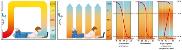
The recommended temperature indicators of the floor surface, depending on the type of room, are:
- living quarters - 29 ° C;
- areas near the outer walls - 35 ° C;
- bathrooms and areas with high humidity - 33 ° C;
- under parquet flooring - 27 °C.
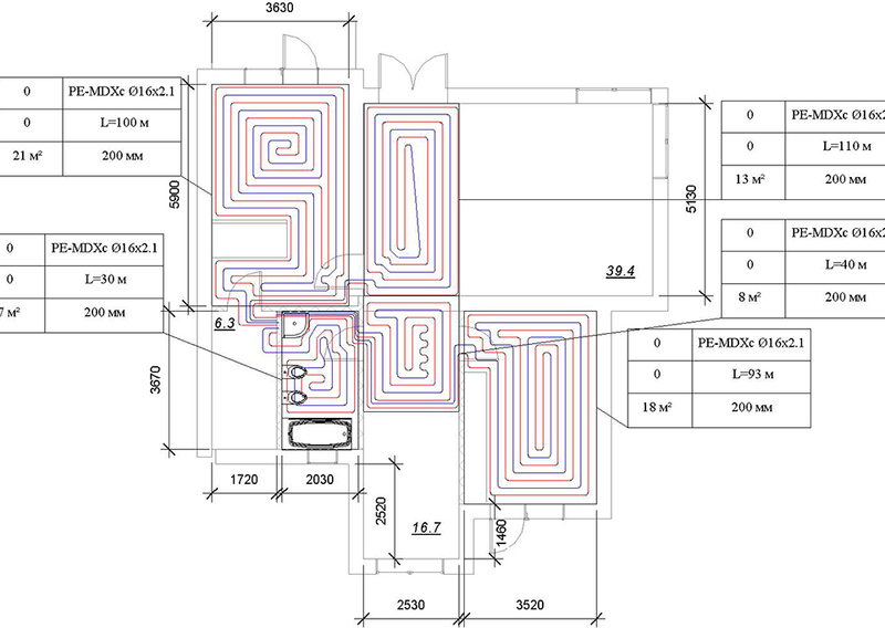
Short pipes require the use of a weaker circulation pump, which makes the system cost effective. A circuit with a diameter of 1.6 cm should not be longer than 100 meters, and for pipes with a diameter of 2 cm, the maximum length is 120 meters.
Decision table for choosing a water floor heating system
We calculate the circulation pump
To make the system economical, you need to choose a circulation pump that provides the necessary pressure and optimal water flow in the circuits. The passports of pumps usually indicate the pressure in the circuit of the longest length and the total flow rate of the coolant in all loops.
The pressure is affected by hydraulic losses:
∆h = L*Q²/k1, where
- L is the length of the contour;
- Q - water flow l / s;
- k1 is a coefficient characterizing the losses in the system, the indicator can be taken from the reference tables for hydraulics or from the passport for the equipment.
Knowing the magnitude of the pressure, calculate the flow in the system:
Q = k*√H, where
k is the flow rate. Professionals take the flow rate for every 10 m² of the house in the range of 0.3-0.4 l / s.


Among the components of a warm water floor, a special role is given to the circulation pump. Only a unit whose power is 20% higher than the actual flow rate of the coolant will be able to overcome the resistance in the pipes
The figures relating to the magnitude of the pressure and flow indicated in the passport cannot be taken literally - this is the maximum, but in fact they are influenced by the length and geometry of the network. If the pressure is too high, reduce the length of the circuit or increase the diameter of the pipes.
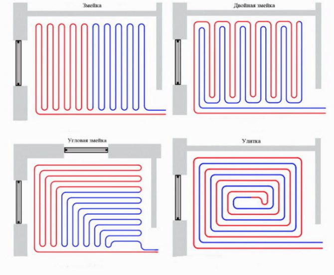
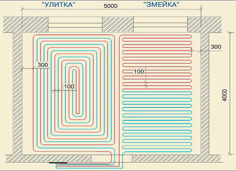
Underfloor heating connection diagrams
Most often, 4 connection schemes are used. Each of them is used in individual cases.It all depends on the type of heating system, the number of rooms, the materials used and other factors.
Directly from the boiler
Such a scheme assumes the presence of a boiler, from which the coolant is distributed to the warm floor and other heating systems (for example, an additional radiator). Cooling, the liquid flows back into the boiler, where it is reheated. The system also uses a pump that regulates the movement of the coolant.
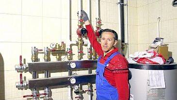
In this video, the specialist shows the finished system installed directly from the boiler. Gives helpful comments on his work:
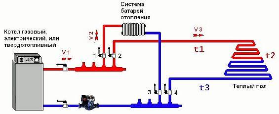
From a three-way valve
This type of connection is usually used in a combined heating system. Considering that water with a temperature of 70-80 degrees comes from the boiler, and a warm floor accelerates the coolant with a temperature of up to 45 degrees, the system needs to somehow cool the hot stream. For this, a three-way valve is installed.
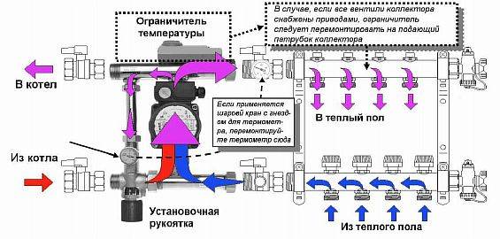
How it works? Pay attention to the diagram:
- Hot water comes from the boiler.
- At the same time, cooled water enters the valve from the other side (which passed through the warm floor, heated it, cooled down and returned back).
- In the center of the valve, hot water and cooled return flow are mixed.
- The thermal head of the valve regulates the required temperature. When it reaches the desired 40-45 degrees, the water flows again through the pipes of the heated floor, heating the room.
The negative point is the inability to accurately distribute the dosage of cold and hot water. In some cases, at the entrance to the warm floor, either too cool liquid or slightly overheated may enter.
But, given that the installation of such a system is very simple and does not “hit the wallet”, many agree to this connection option. For example, an excellent option would be a choice where the customer does not have high requirements and wants to save money.
An example of a real circuit:
In this video, the installer talks in detail about the filling of the three-way valve, in which cases it is better to install it and what varieties of it are. The engineer voices possible errors and gives recommendations on how to avoid them:
From the pumping and mixing unit
The scheme is mixed. It has a radiator heating zone, underfloor heating, a pumping and mixing unit. Mixing passes from the cooled water of the warm floor, which came from the "return", to the heated boiler room.


A balancing valve is installed in each mixing unit. It accurately doses the volumes of the cooled liquid (return) to be mixed into hot water. This helps to achieve accurate data on the temperature of the coolant inlet to the warm floor for heating it.
From the radiator
In many rooms and apartments it is forbidden to use such a scheme for connecting a warm floor. But where it is permissible (permission is taken from the housing and communal services or the management company of your house), then the circuit is carried out directly through the radiator (battery).
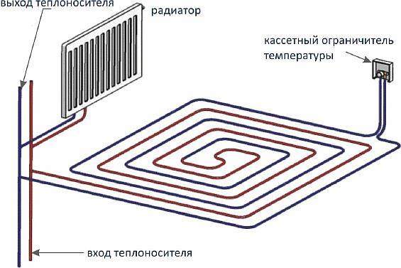
The heated water flows directly from the radiator to the underfloor heating. The cooled water enters the cassette temperature limiter and returns to the radiator (coolant outlet).
Installation is the easiest and cheapest. But there are some drawbacks - the water from the radiator is too hot for a warm floor. Hence the consequences - the fragility of the system and material, the floor is too hot. In the summer season, when the heating is turned off, the floor will be cold.
The ideal place to use floor heating from a radiator is a bathroom, a loggia.
The video shows the installation of a warm floor directly from a common heating radiator. The installer shows in detail how to do this with minimal losses. Installation of 3 circuits: kitchen, bathroom, living room. The apartment is small
Why is it better to use a pipe with an outer diameter of 16 mm?
To begin with, why is a 16 mm pipe being considered?
Everything is very simple - practice shows that for "warm floors" in a house or apartment of this diameter is enough. That is, it is difficult to imagine a situation where the circuit does not cope with its task. This means that there is no really justified reason to use a larger, 20-millimeter one.
Most often, in the conditions of an ordinary residential building, pipes with a diameter of 16 mm are more than enough for "warm floors"
And, at the same time, the use of a 16 mm pipe provides a number of advantages:
- First of all, it is about a quarter cheaper than the 20mm counterpart. The same applies to all the necessary fittings - the same fittings.
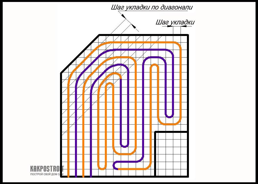
- Such pipes are easier to lay, with them it is possible, if necessary, to perform a compact step of laying out the contour, up to 100 mm. With a 20 mm tube, there is much more fuss, and a small step is simply impossible.
A pipe with a diameter of 16 mm is easier to fit and allows you to maintain a minimum step between adjacent loops
- The volume of coolant in the circuit is significantly reduced. A simple calculation shows that in a linear meter of a 16 mm pipe (with a wall thickness of 2 mm, the inner channel is 12 mm) holds 113 ml of water. And in 20 mm (inner diameter 16 mm) - 201 ml. That is, the difference is more than 80 ml per just one meter of pipe.And on the scale of the heating system of the whole house - this literally translates into a very decent amount! And after all, it is necessary to ensure the heating of this volume, which entails, in principle, unjustified energy costs.
- Finally, a pipe with a larger diameter will also require an increase in the thickness of the concrete screed. Like it or not, but at least 30 mm above the surface of any pipe will have to be provided. Let these "unfortunate" 4–5 mm do not seem ridiculous. Anyone who was involved in pouring the screed knows that these millimeters turn into tens and hundreds of kilograms of additional concrete mortar - it all depends on the area. Moreover, for a 20 mm pipe, it is recommended to make the screed layer even thicker - about 70 mm above the contour, that is, it turns out to be almost twice as thick.
In addition, in residential premises very often there is a “struggle” for every millimeter of floor height - simply for reasons of insufficient “space” to increase the thickness of the overall “pie” of the heating system.
An increase in the diameter of the pipe invariably leads to a thickening of the screed. And this is not always possible, and in most cases it is completely unprofitable.
A 20 mm pipe is justified when it is necessary to implement a floor heating system in rooms with a high load, with a high intensity of people's traffic, in gyms, etc. There, simply for reasons of increasing the strength of the base, it is necessary to use more massive thick screeds, for the heating of which a large heat exchange area is also required, which is exactly what a pipe of 20, and sometimes even 25 mm, provides. In residential areas, there is no need to resort to such extremes.
It may be objected that in order to "push" the coolant through a thinner pipe, it will be necessary to increase the power indicators of the circulation pump. Theoretically, the way it is - the hydraulic resistance with a decrease in diameter, of course, increases. But as practice shows, most circulation pumps are quite capable of this task.


Below, attention will be paid to this parameter - it is also linked to the length of the contour. This is what calculations are made in order to achieve optimal, or at least acceptable, fully functional performance of the system.
So, let's focus on the pipe exactly 16 mm. We will not talk about the pipes themselves in this publication - that is a separate article of our portal.
What affects the operation of a warm water floor
How to ensure that the warm floor is really such and creates a comfortable temperature of the floor covering. Often, due to the large length of the circuit, a high value of hydraulic resistance is observed.
For the correct operation of the system in a house with several floors, a separate low-power pump is installed at each level or one high-power pump is connected to the collector.
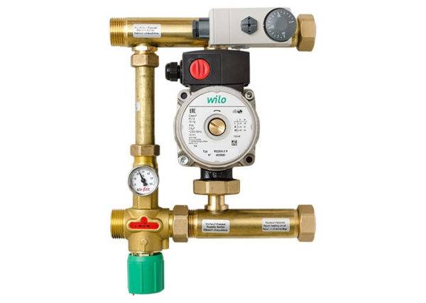
Pump group
When choosing a pump, take into account the calculated data, the volume of the coolant and pressure. However, it is worth remembering that to determine the level of hydraulic resistance, it is not enough to know the length of the pipe. You will need to take into account the diameter of the pipes, valves, splitters, laying pattern and main bends. More accurate calculations are obtained using a special computer program into which the main indicators are entered.
As an alternative, it is possible to use standard equipment with already known technical characteristics.The hydraulics of the system, by maneuvering its parameters, is adjusted to the characteristics of the pump.
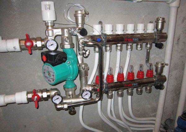
Manifold with installed pump
Connection to an individual heating boiler
The presence in an apartment or a private house of an individual boiler for heating removes all organizational problems to allow the installation of water-heated floors. In this case, the connection of a warm water floor does not require any permissions. Depending on the conditions of location and operation of the facility, boilers can be of various types:
- on gas fuel;
- on liquid fuel (solar oil, fuel oil);
- solid fuel: firewood, pellets, coal;
- electrical;
- combined.
In apartments of multi-storey buildings, gas or electric heating boilers are most often used; connection to the central heating system of the underfloor heating circuit is not required. In this case, the scheme differs slightly, and the functional purpose of the main elements remains the same.
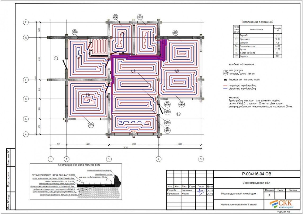
Scheme of a water-heated floor system in a private house with an autonomous boiler
Main elements:
- boiler;
- expansion tank;
- manometer;
- circulation pump;
- collector for underfloor heating;
In contrast to the case with central heating, the connection of underfloor heating to the boiler does not require the installation of a three-way valve to regulate the temperature of the heat carrier. Its installation is not mandatory, the temperature change is done from the boiler control panel. Temperature control sensors are also located on the external control panel.
The expansion tank serves to maintain a stable pressure in the system; when heated, the volume of liquid increases.In order not to collapse the collector of the warm floor, the pump and other expensive elements in the pipeline system, the tank compensates for the expansion of the volume of the coolant. The pressure gauge shows the pressure in the pipes. The main thing is that before pouring a warm floor with a solution, you need to check the performance of all nodes.
Control panel on the boiler body
Regardless of the modification of the device and its manufacturer, all panels have basic options, and some additional programming functions:
- buttons or regulators for increasing and decreasing the temperature of the coolant at the supply;
- button for automatic setting of a comfortable, economical temperature regime, room temperature - 20-22 ̊С;
- program control is possible, setting the modes "winter", "summer", "holidays", "system protection function against liquid freezing".
How to make specific settings for boilers with different control panels is described in the operating instructions. Filling a water-heated floor with a solution for a separate boiler is done in the same way as for central heating.


Remote control panel
Heat distribution: features
Since the area of the premises in the house varies, the contours also have different lengths, so it is necessary to ensure the same hydraulic pressure in all parts of the system. It should be taken into account that the pump is a constant value.
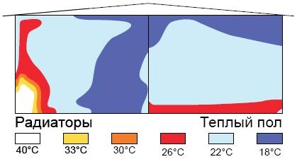
Distribution of heat from different sources
The supply of the same volume of water to the circuits of each length leads to the fact that in a longer one the coolant cools faster and at the outlet its temperature will differ from the coolant of a shorter profile.As a result, the floor surface will warm up unevenly - overheating will be observed somewhere, and somewhere on the contrary, the coating will turn out to be cold.
Benefits of using underfloor heating
Due to the large hydraulic resistance, the coolant may not flow into a long circuit at all, since it will move to shorter circuits with less resistance. To prevent this from happening, the system is equipped with a distribution manifold, which allows you to maintain a balance of supply and uniform heating of the coolant in each loop.
Laying technology of electric underfloor heating system
Mounting the temperature controller and forming a groove for the mounting ends of the heating sections
Here it is important to take into account the diameter of the temperature sensor cable and the dimensions of the cable channels for the main power wire. The thermostat should be located at a height of 30-50 cm
Mounting the temperature controller and forming a groove for the mounting ends of the heating sections
Surface preparation
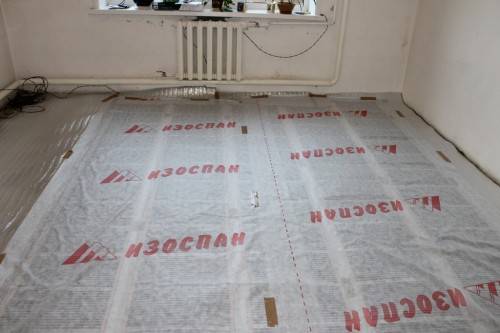
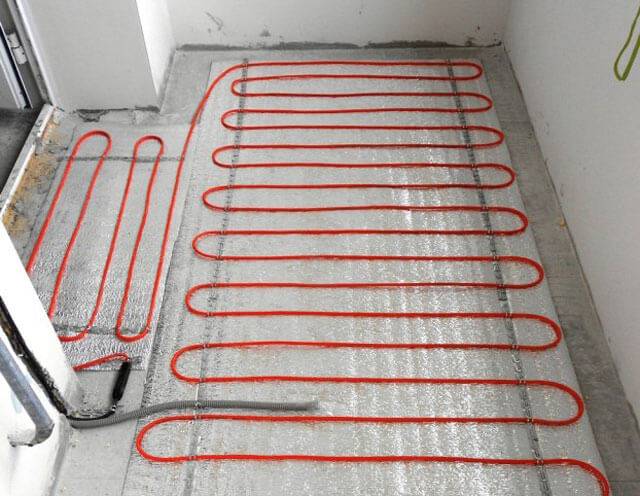
The floor is cleared of construction debris, a layer of waterproofing is laid, and a damper tape is fixed along the edges - it will not allow unnecessary heat loss from the walls. We lay these floors with a 10 cm approach to the wall, so that they are then above the finished warm floor - the excess will be carefully cut off at the very end of the installation.
In order not to "give" heat to the neighbors from below or the basement, we make thermal insulation. Traditionally, this is expanded polystyrene or extruded polystyrene foam. For sufficiently warm rooms, a 4 mm foam layer is enough. Insulation is laid over the entire area without exception.
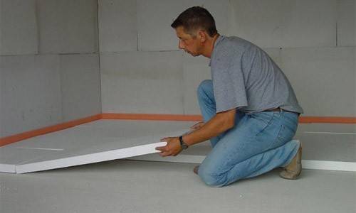
thermal insulation
thermal insulation
markup
Places where furniture, partitions, plumbing and engineering equipment will stand are separated by tape - these areas are not subject to heating. After that, a drawing is necessarily made based on the laying technology of a particular type of underfloor heating (heating cable or mats).


Mounting. Walkthrough
- Bring the ends of the wiring of the mounting section to the thermostat. Fix the beginning of the cable and the coupling.
- Start laying the section, avoiding intersections and cable touches. The optimal distance between the turns is from 8 cm. The laying step is strictly observed along the entire perimeter. The bends are made smooth, without sharp fractures and tensions.
Bends are made smooth, without sharp fractures and tensions
Cable loops are very convenient to fix with protruding tabs provided on the mounting tape
Install temperature sensor.
The end of the plastic tube, near which the sensor is located, is covered with a plug, the second one is connected to the thermostat and inserted into the groove left for it. It is customary to adhere to the bending radius of the tube - 5 cm, and the distance from the wall to the very location of the sensor - 50-60 cm. So the device will be able to correctly determine the temperature, and in the event of a breakdown, you will not have to open the floor.
- Fix the tube with the solution. Keep in mind that the coils must be located at an equal distance from the groove with the tube.
- Connect the sensor and the mounting section to the thermostat, check the connections.
- Test system performance. To do this, apply voltage for 1 minute. If everything is properly laid and connected, the sensor on the controller will light up and the floor will start to heat up.
- Power off.
- Draw a layout diagram. You can even take a photo.This is very useful if you have to make repairs or install additional engineering communications. On the diagram, be sure to indicate the locations of all couplings and the sensor.
-
Make a screed or self-leveling floor. The solution, which must contain plasticizers, is poured to a height of 3-5 cm, and air pockets are not allowed, since they will lead to local overheating.
After about a month, the screed will dry completely and it will be possible to make a decorative coating on top of it. It is better to use materials with high thermal conductivity - tiles, porcelain stoneware, etc. The main thing is that the efficiency of the heating system is not lost due to the upper flooring.
| Retreat from the walls | |
| Distance from other heating elements | |
| Groove parameters for mounting temperature sensor |
|
| Formula for calculating the laying step |
|
| Maximum deviation from calculated paving spacing |
Important points!
- During the installation process, it is better not to step on the cable at all. Just in case, use shoes with soft soles. To move around the room without harm to the future warm floor, you can cover the areas with the cable laid with plywood sheets.
- Accurate work with a construction tool is a prerequisite. Any mechanical damage to the cable makes the heating system unusable or unsafe.
- In no case should you turn on the system while the solution is still wet (drying time - 28-30 days)!
Types of electrical cables
The following types of cables are on the market:
- Resistive single-core.This option is characterized by maximum simplicity and low cost. A current flows through the core of the cable, and electrical energy is converted into heat. A key feature of single-core cables is the need to connect them on both sides - and this is sometimes difficult.
- Resistive two-wire. In this embodiment, there is not only a heating, but also a conductive core. Thanks to the second core, such a cable can be connected only on one side - this simplifies installation and reduces the level of electromagnetic radiation generated by the structure.
- Self-adjusting. In this type of cable, the main element is polymer sleeves that convert electricity into heat. Self-regulating cables are considered the most efficient and easiest to operate, but they are also more expensive than their counterparts.
Thinking over the plan for laying out underfloor heating, you need to take into account the main rule - resistive cables should not be placed under furniture and other objects in the room. The thing is that with this arrangement, the cable will definitely overheat, and the warm floor will simply become unusable. When choosing the step of laying the turns, you need to build on the required power of the underfloor heating and the performance of the cable itself.
When the cable is installed, it is necessary to install a temperature sensor in the corrugated tube. To install the sensor, a place is usually selected between the turns of the cable, remote from the wall at a distance of about 0.5-1 meters. The part of the wire that provides the connection between the thermostat and the temperature sensor is laid in a vertical strobe.


