- Oil switch VMP-10
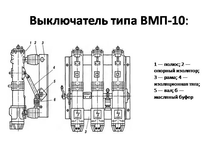
- Switch type VMP-10
- Scope of VMP-10 circuit breaker
- The structure of the symbol of the circuit breaker VMP(E)-10-X/X U2
- Main types of oil circuit breakers
- Oil tank switches
- Low oil circuit breakers
- Design features and principle of operation
- Efficiency
- MV operating rules
- 2.4. Breaker classification
- The principle of operation of the three-tank circuit breaker
- Main types of oil circuit breakers
- Oil tank switches
- Low oil circuit breakers
- Classification of oil switches
- Pros and cons of oil switches
- System advantages
- The device and principle of operation of switches.
- Oil circuit breakers
- The device and design of the air circuit breaker
- Conclusions and useful video on the topic
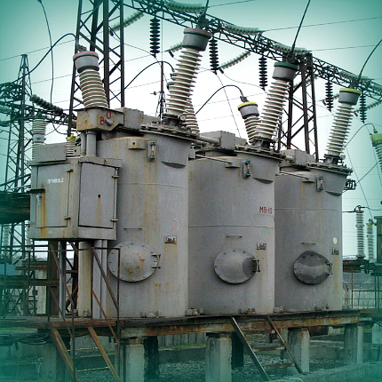
Oil switch VMP-10
The VMP-10 oil circuit breaker is a liquid three-pole high-voltage circuit breaker with a small volume of arc extinguishing liquid (oil as a dielectric).
Oil circuit breakers VMP-10 are designed for switching high-voltage circuits of three-phase alternating current in the nominal mode of operation of the installation, as well as for automatic disconnection of these circuits in case of short circuits and overloads that occur during emergency modes.
The VMP-10 circuit breaker is controlled by a DC electromagnetic drive built into the circuit breaker frame.
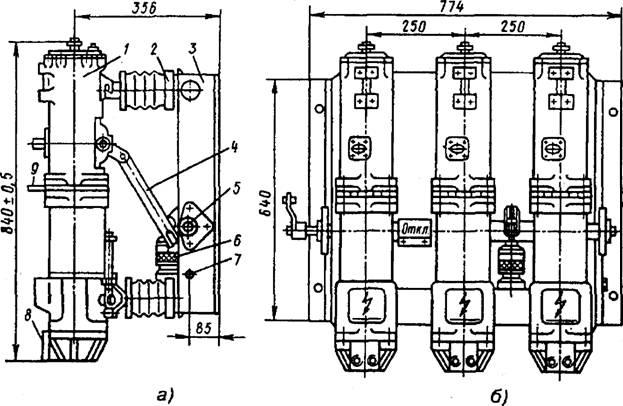
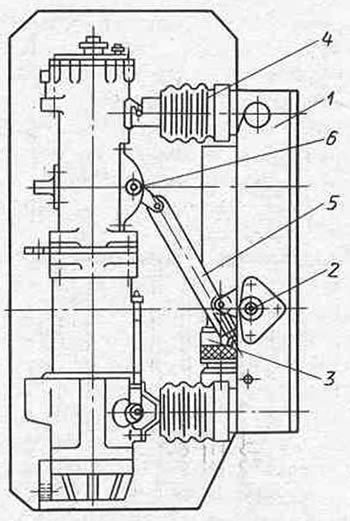
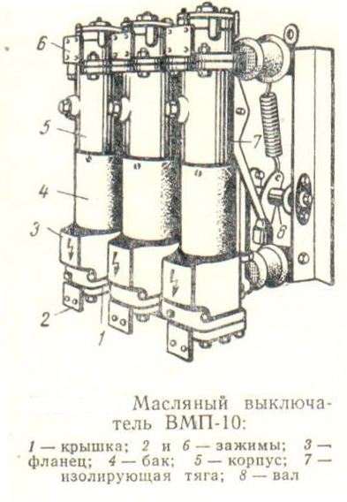
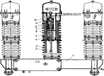
Switch type VMP-10
- 1 - pole;
- 2 - support insulator;
- 3 - frame;
- 4 - insulating rod;
- 5 - shaft;
- b - oil buffer. Dimensions of VMP-10 circuit breakers, mm, are as follows: For stationary switchgears KSO…. 250 x774
For complete switchgears KRU….. 230 x 666
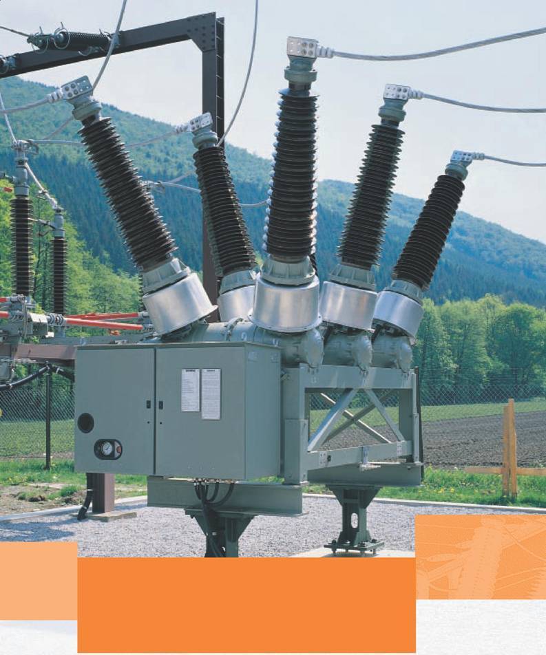
Scope of VMP-10 circuit breaker
The VMP-10 circuit breaker (oil suspended circuit breaker, see figure) with an oil mass of 4.5 kilograms is designed for installation in conventional switchgear, VMP-10K, VMP-10P and VMPP-10 circuit breakers are for small-sized complete switchgear with withdrawable switchgear carts. The latter differ from the VMP-10 circuit breaker in a smaller width, which is achieved by bringing the poles closer together by installing insulating partitions between them. Circuit breakers VMP-10P and VMPP-10 have built-in spring drives.
In closed switchgears, low-oil circuit breakers VMP-10, VMPP-10, VMPE-10 and others (which differ from each other in the type of drive) are used for KSO prefabricated chambers, as well as VMP-10K for switchgear.
Low-oil switches are produced by domestic enterprises of the VMP series (oil suspended switch) with a built-in spring or electromagnetic drive (varieties of VMPP and VMPE), oil switches of the VK-10 column type with a spring drive, oil switches of the VMG-10 pot type, etc.
Tank oil circuit breakers that have survived in operation are currently being replaced by low-oil circuit breakers, and now vacuum, SF6, etc.
In networks, circuit breakers with a small volume of oil VPM-10, VPMP-10, VMP-10, VMP-10K, VMP-10P, VMPP-10 are used.
The structure of the symbol of the circuit breaker VMP(E)-10-X/X U2
- VMP – low oil suspended switch.
- E – electromagnetic drive PE-11.
- 10 – rated voltage, kV.
- X – rated breaking current (20; 31.5) kA.
- X - rated current of the switch (630; 1000; 1600), A.
- U3 – climatic version and category of placement.
AT during the operation of the circuit breaker, it was found that the guide rods, along which the nylon guide block slides, can rotate around its axis. The rods have metal stops to limit the course of the collector rollers.
In the normal position, the stops pass through the slots of the nylon block. When turning the guide rods, the stops are shifted to the side relative to the slots, and at the moment the switch is turned on or off, the nylon block hits the stops and breaks.
To eliminate this defect, before putting the circuit breaker into operation, set the locking screws that secure the position of the guide rods.
Main types of oil circuit breakers
The design of oil circuit breakers is of two main types:
- Tank. They have a large volume of oil. Equipped with one large tank for three contacts of three-phase voltage at once;
- Potted (low oil). With a smaller oil volume, but with an additional arc suppression system and three separate tanks. In them, at each phase there is a separate metal cylinder filled with oil, in which the contacts are broken and the electric arc is suppressed.
Oil tank switches
Most often they are designed for relatively small tripping currents. They are produced in single-tank structures (three poles are in one tank) with an operating voltage of up to 20 kV.and for voltages above 35 kV - three-tank (each of the phases is located in a separate tank) with personal or group switching drives. Tank switches are supplied with electromagnetic or air pneumatic actuators. It is possible to work with automatic reclosing (AR).
 Oil tank circuit breakers, produced for voltages above 35 kV, have current transformers built inside for measuring and protection circuits. They are mounted and fixed on the inner section of the bushing and closed with a lid. Thus, the conductive rod serves as the primary winding. Tank switches on operating voltage 110 kV and above are sometimes equipped with capacitive voltage transformers.
Low oil circuit breakers
Compared to tanks, oil here serves exclusively as an arc-extinguishing medium, and the insulation of current-carrying parts and the arc-extinguisher regarding ground faults is carried out through a solid insulating material (ceramics, textolite, and various epoxy resins). This is a VMP or VMG type oil circuit breaker.

They have radically smaller dimensions, weight, as well as a significantly lower explosion and fire hazard. The presence of built-in capacitive voltage and current transformers in these high-voltage devices significantly complicates the design of switches and increases their overall dimensions.
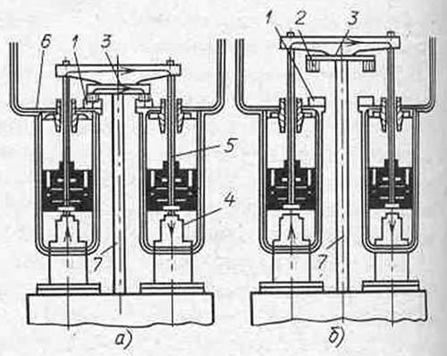
Oil circuit breakers by their design can be produced by the manufacturer of two types of movement of the contact group:
- arc chutes from below (moving contact is performed from top to bottom);
- arc chutes from above (moving contact occurs vice versa from bottom to top).This type is more promising in terms of improving the tripping capability.
The circuit breaker can be equipped with a built-in protection and control mechanism. These are relays such as:
- instantaneous maximum current
- time delay
- undervoltage relay (to protect electrical equipment from operation at non-rated voltage)
- shutdown electromagnets,
- auxiliary block contacts.
The increase in the rated operating current is carried out here due to the artificial blowing mechanism of both the supply tires and the contact system. Recently, water cooling has begun to be used for these elements heated by the passage of current.
The low oil circuit breaker for outdoor installation consists of three main key parts:
- arc quenching device, which is placed in a porcelain shell;
- porcelain support columns;
- bases, that is, frames.
The insulating cylinder covers the arc quenching device and performs a protective function. Its main protective purpose is a porcelain shell, so that during the high pressure that occurs when the oiler is turned off, it simply does not burst.
Design features and principle of operation
The appearance of the classic model of an electronic switching device is almost identical to the touch panel and is a screen made of a glossy electrochromic material (crystal glass) with markings applied to it. A wide variety of design options, colors and instrument configurations are presented.
Regardless of the external characteristics and the number of connected consumers, the structurally sensory device consists of the following main parts:
- controller or control unit. Behind the decorative front screen is the active surface of the sensing element, which reacts to various stimuli. Based on the type of touch switch, the stimuli are: touching the object of influence, in some models, approaching, clapping, voice command.
- semiconductor converter. In the previous block, a signal is generated, which in this section is converted into an electrical one of sufficient power for operation.
- Switching part. By means of the switch, the main actions in the electrical circuit are carried out: opening, closing or smooth regulation of the degree of load applied to the lamp.
Based on the design of the electronic product, its principle of operation is obvious: by lightly touching the panel with your fingers, a signal is produced that is converted and causes the relay to turn on.
Additional functions built into a universal touch-type switch are often used to equip a smart home system: control of the operation of heating devices, opening / closing window shutters, and others
Efficiency
Today, various types of air circuit breakers have become more advanced and functional, this has been achieved by making the following additions:
- Generator sets use a forced cooling circuit.
- High-quality materials and careful execution of structural elements ensured great reliability and a long service life before the need for repairs.
- Switching overvoltages have acquired a limitation, the presence of which plays a special role for high voltage devices.
- The modular layout of the series makes it possible to create several series from identical modules, characterized by a wide voltage range, to test and implement devices that are simple to manufacture, install and subsequent operation.
- Use of control schemes with fast response and minimal time spread. Their main task is to ensure the operation of devices for a significant excess of voltage and disconnection during a half-cycle. Also, due to them, devices with synchronous switching on and off function.
- Arc extinguishing elements are placed in compressed air. This achieves high throughput characteristics for rated voltage, reliable insulation of gaps between contacts, fast response and switching properties. Most often, the air pressure is in the range of 6-8 MPa.
MV operating rules
Repair, operating personnel, specialists associated with the maintenance and operation of oil circuit breakers are required to know the relevant instructions, device, and the principle of operation of the equipment. During operation, employees serving the MW are required to control:
- Operating voltage, load current. Indicators should not go beyond the table values.
- The height of the oil column in the poles, no leakage.
- The presence of lubrication on the rubbing parts. Contacts can lose mobility and freeze if the lubricant of the rubbing elements becomes thick and dirty.
- Dustiness of the premises in which the switchgears are located.
- Compliance of the mechanical characteristics of operated circuit breakers with tabular standards.
After each disconnection of the short circuit, the equipment must be inspected. Information about these shutdowns is recorded in a special log. A defect log must be available to record information about malfunctions detected during the operation of the unit. The circuit breaker on which the trip occurred as a result of a short circuit is subject to inspection.
Check for oil leakage. If this happened, moreover, in large numbers, then this indicates an abnormal short circuit shutdown. Equipment is decommissioned and inspected. When the oil is dark, a change is needed. The rate of opening is adversely affected by the viscosity of the oil, which increases as the temperature drops. Sometimes it becomes necessary to replace the old lubricant during repairs with a new one: CIATIM-221, GOI-54 or CIATIM-201.

After removing the MW from operation, the support insulators, rods, insulation of the tanks for cracks are subject to a thorough inspection. Heavily contaminated insulation is wiped. The need for extraordinary repairs appears after a certain number of short circuits.
Periodic inspection (PO) is performed monthly
In this case, pay attention to the degree of heating of the switch. TR (maintenance) is carried out annually. It includes such work as checking and eliminating defects in fasteners, drive kinematics, oil level, seals
Insulating parts are also checked for their integrity.
It includes such work as checking and eliminating defects in fasteners, drive kinematics, oil level, seals. Insulating parts are also checked for their integrity.


After 3-4 years after the overhaul, perform an average (SR).It includes the entire set of TR works plus additionally perform measurements of the transient resistance of the poles and check the mechanical and speed parameters. If a discrepancy between the controlled characteristics and tabular data is detected, the circuit breaker is disassembled, adjusted and a full range of high-voltage tests is performed.
During an extraordinary repair, they basically try to leave the previous adjustment unchanged. For this reason, the switch is disassembled to a minimum. The frequency of overhaul is from 6 to 8 years. In its scope, a general inspection is performed, the cylinders are removed from the frame, the tires are disconnected, the drive, arcing devices, auxiliary contacts are repaired.
After all, they make adjustments, paint, connect tires, and test. All work is documented.
2.4. Breaker classification
Main classification
switches according to the method of extinguishing the arc:
1.
Oil switches. AT
these circuit breakers arc formed
between
contacts, burns in the transformer
oil. Under the influence of arc energy
the oil decomposes and the resulting gases
and the vapors are used to extinguish it.
Depending on the type of isolation
current-carrying parts distinguish tank
switches and low-oil. First
live parts are isolated
between themselves and from the earth with the help of oil,
in steel
tank connected to ground. In low oil
circuit breakers current-carrying insulation
parts from the earth and among themselves is produced
by using
solid dielectrics and oils.
AT
our country oil circuit breakers
were the main type of switches
for voltage from 6 to 220 kV. At present
time oil switches
are not issued.
2. electromagnetic
switches. By
these principles
switches
similar to permanent contactors
current with labyrinth
slotted
camera. The arc is extinguished after
by increasing the resistance
arcs
due to its intense elongation
and cooling.
Issued on
rated voltages not higher than 10 kV.
3. Air
switches. AT
used as a quenching medium
compressed
air in a pressurized tank
1-5 MPa. At
turning off
compressed air from the tank is supplied to
arcing device.
Arc,
formed in the arc chute chamber
devices (DU), blown
intense
airflow escaping into
atmosphere. Insulation
current-carrying
parts to each other is carried out with
solid
dielectrics
and air.
Issued
for rated voltages from 110 to 1150
kV.
4. SF6
switches. AT
these switches
arcs
carried out
by cooling it moving with
high speed
SF6
(sulfur hexafluoride SF6),
which is also used as an insulating
Wednesday.
Issued on
voltage from 35 to 500 kV.
5. vacuum
switches. AT
these switches contacts
disperse
under vacuum (pressure is 10-4
Pa). Arising from
divergence
contacts, the arc quickly dies out due to
intensive diffusion
charges
in a vacuum.
Issued on
voltage 10 and 35 kV.
6.
switches
loads. it
simple high voltage switches
to open and close circuits,
under load. To disable
short circuit currents in series
with circuit breaker
the fuse turns on.
Issued on
voltage 6 and 10 kV.
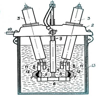
The principle of operation of the three-tank circuit breaker
The three-tank switch has a slightly different principle of operation, which is associated with its use in a high voltage network. The oil circuit breaker, which is used in a network with a voltage above 35 kV, has a special mechanism in the arc extinguishing chamber that creates a blast. The arc extinguishing system used can consist of several modes of operation. They allow you to increase the speed of extinguishing the arc during the separation of the contact.


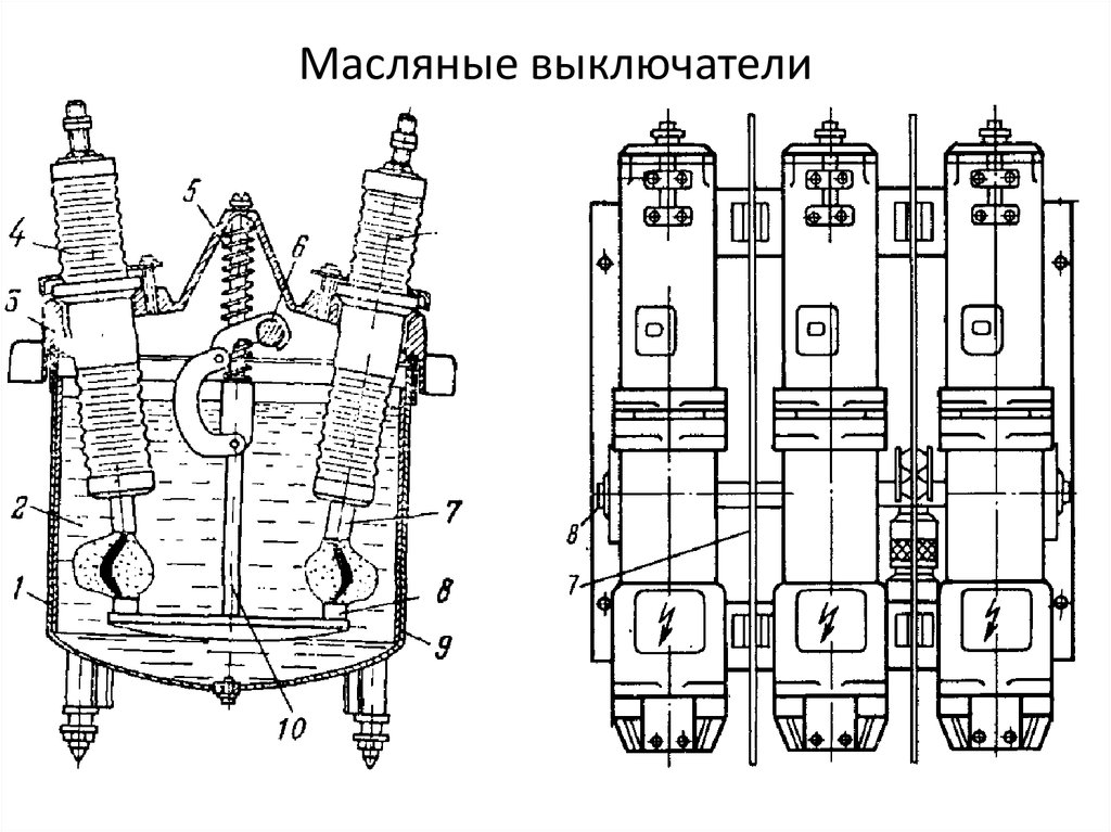


In order to secure this process, the electricity-transmitting elements are placed in a special oil tank, with a separate tank used for each phase. Various oil circuit breaker drives are also used, allowing the working fluid to be supplied in the selected direction. The system has a special element for controlling the size of the arc, which is represented by a shunt. After the disappearance of the formed arc, the current supply stops completely.
Main types of oil circuit breakers
The design of oil circuit breakers is of two main types:
- Tank. They have a large volume of oil. Equipped with one large tank for three contacts of three-phase voltage at once;
- Potted (low oil). With a smaller oil volume, but with an additional arc suppression system and three separate tanks. In them, at each phase there is a separate metal cylinder filled with oil, in which the contacts are broken and the electric arc is suppressed.
Oil tank switches
Most often they are designed for relatively small tripping currents. They are produced in single-tank structures (three poles are in one tank) with an operating voltage of up to 20 kV.and for voltages above 35 kV - three-tank (each of the phases is located in a separate tank) with personal or group switching drives. Tank switches are supplied with electromagnetic or air pneumatic actuators. It is possible to work with automatic reclosing (AR).
Oil tank circuit breakers, produced for voltages above 35 kV, have current transformers built inside for measuring and protection circuits. They are mounted and fixed on the inner section of the bushing and closed with a lid. Thus, the conductive rod serves as the primary winding. Tank circuit breakers for an operating voltage of 110 kV and above are sometimes equipped with capacitive voltage transformers.
Low oil circuit breakers
Compared to tanks, oil here serves exclusively as an arc-extinguishing medium, and the insulation of current-carrying parts and the arc-extinguisher regarding ground faults is carried out through a solid insulating material (ceramics, textolite, and various epoxy resins). This is a VMP or VMG type oil circuit breaker.
They have radically smaller dimensions, weight, as well as a significantly lower explosion and fire hazard. The presence of built-in capacitive voltage and current transformers in these high-voltage devices significantly complicates the design of switches and increases their overall dimensions.
Oil circuit breakers by their design can be produced by the manufacturer of two types of movement of the contact group:
- arc chutes from below (moving contact is performed from top to bottom);
- arc chutes from above (moving contact occurs vice versa from bottom to top).This type is more promising in terms of improving the tripping capability.
The circuit breaker can be equipped with a built-in protection and control mechanism. These are relays such as:
- instantaneous maximum current
- time delay
- undervoltage relay (to protect electrical equipment from operation at non-rated voltage)
- shutdown electromagnets,
- auxiliary block contacts.
The increase in the rated operating current is carried out here due to the artificial blowing mechanism of both the supply tires and the contact system. Recently, water cooling has begun to be used for these elements heated by the passage of current.
The low oil circuit breaker for outdoor installation consists of three main key parts:
- arc quenching device, which is placed in a porcelain shell;
- porcelain support columns;
- bases, that is, frames.
The insulating cylinder covers the arc quenching device and performs a protective function. Its main protective purpose is a porcelain shell, so that during the high pressure that occurs when the oiler is turned off, it simply does not burst.
Classification of oil switches
The use of oil switches began at the end of the century before last. Almost until the middle of the twentieth century, there were simply no other disconnecting devices in high-voltage networks. There are two large groups of these devices:
- Tank, for which the presence of a large volume of oil is characteristic. For this equipment, it is both the medium in which the arc is extinguished and the insulation.
- Low oil or low volume. The name itself speaks about the amount of filler in them.These switches contain dielectric elements, and oil is needed here only for arc extinguishing.
The former are used mainly in distribution installations from 35 to 220 kV. The second - up to 10 kV. Low-oil devices of the VMT series are also used in outdoor switchgears designed for 110 and 220 kV.
The principle of arc extinguishing in both types is identical. The arc that appears when the high-voltage contacts of the switch open causes rapid evaporation of the oil. This leads to the creation of a gaseous envelope around the arc. This formation consists of oil vapor (about 20%) and hydrogen (H2). The arc gap is deionized as a result of the rapid cooling of the arc shaft by mixing high and low temperature gases in the sheath.
At the moment of arcing in the contact zone, the temperature is very high - about 6000⁰. Depending on the installation, switches are distinguished that are used for indoor, outdoor use, as well as for use in KRP - complete switchgears.

Pros and cons of oil switches
These devices have a relatively simple design. They have good breaking capacity, do not depend on weather conditions. In the event of a malfunction, repair work can be carried out. Tank MW are suitable for outdoor installation. There are conditions for mounting built-in current transformers.


An important role in the operation of the MW is played by the rate of contact divergence. A situation may arise when the contacts diverge at great speed and the arc instantly reaches a length that is critical for it. In this case, the value of the recovering voltage may not be enough to break through the intercontact gap.
Tank switches have more disadvantages. The first is the presence of a large volume of oil, hence the considerable dimensions of these units and switchgears. The second is fire and explosion hazard, in emergency situations the consequences can be the most unpredictable.
The oil level both in the tank and in the inputs, as well as its condition, must be kept under periodic control. If there is a MW power supply in the serviced networks, it is necessary to have a special oil economy.
System advantages
This type of arc extinguishing system has a number of features, due to which it is used in many power supply circuits. The advantages of the system include the following:
High circuit interruption efficiency, which allows the use of such equipment in high voltage networks.
The simplicity of the design makes it reliable and maintainable.
Repair of oil switches should be carried out exclusively by professionals, since such equipment is responsible for carrying out an important command from an automatic control system or operator. Also, this quality determines the relatively low cost of this type of equipment.
The device and principle of operation of switches.
4.1. Principle of operation.
4.1.1. Circuit breakers VPM-10 are liquid high-voltage circuit breakers with a small volume of arc extinguishing liquid (transformer oil).
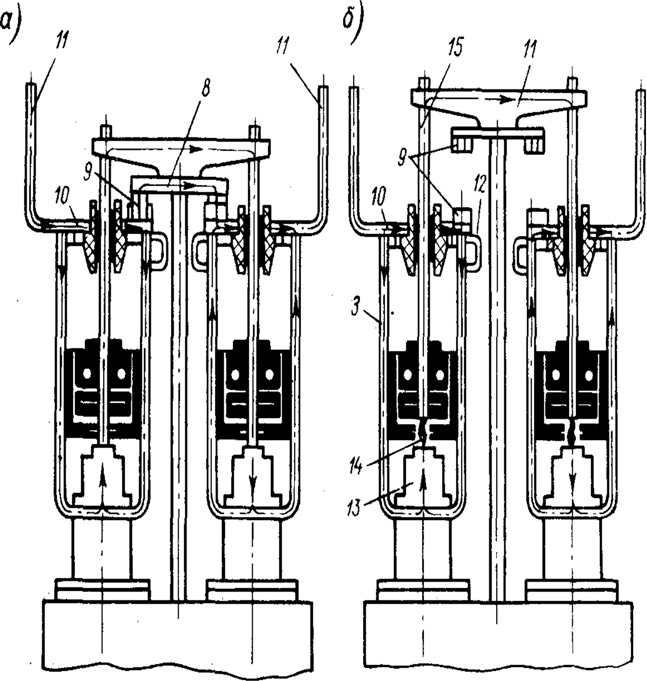
4.1.2. The principle of operation of the circuit breaker is based on extinguishing the electric arc that occurs when the contacts are opened by the flow of the gas-oil mixture resulting from the intensive decomposition of transformer oil under the action of the high temperature of the arc.This flow receives a certain direction in a special arc quenching device located in the arc burning zone.
4.1.3. The circuit breakers are switched on due to the energy of the drive (PE - 11 or PP - 67), and disconnected - due to the energy of the circuit breaker opening springs.
4.2. Switch device.
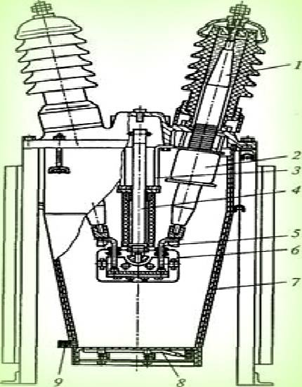
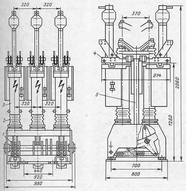
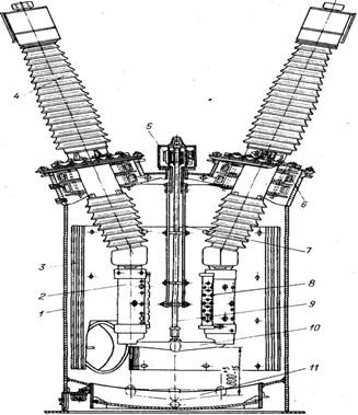
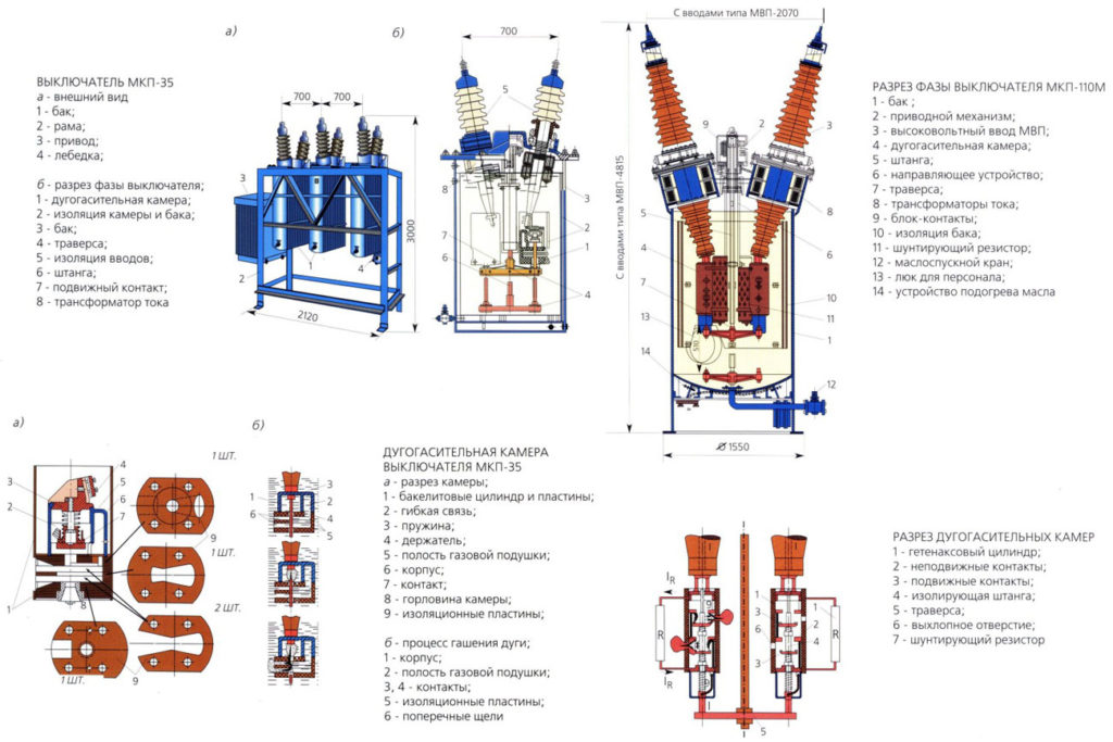
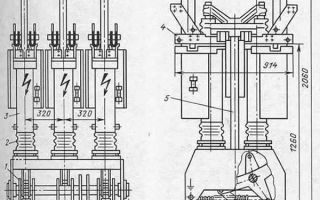
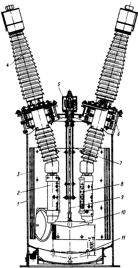
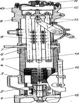
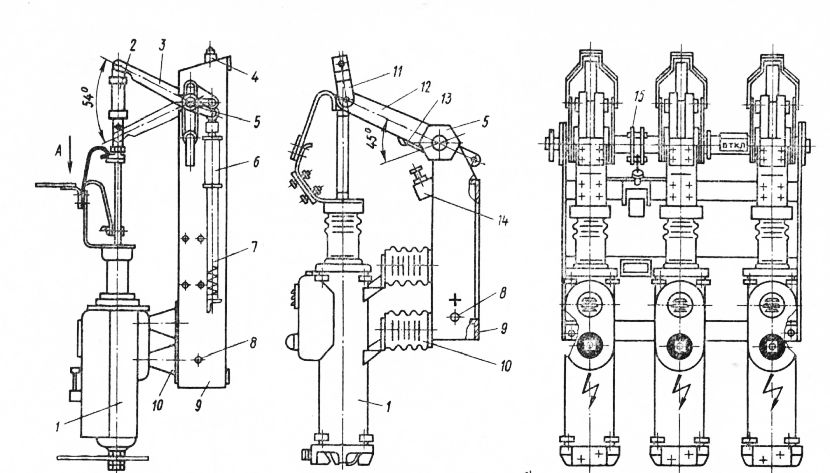
A general view of the VPM-10 circuit breaker is shown in fig. 1. Three poles 1 of the switch are suspended on support insulators 2 to a welded frame 3. Support insulators have an internal elastic mechanical fastening. The movement from the switch shaft to the movable contacts 7 poles is transmitted by insulating levers 10 and earrings 11.
FIG. 1. General view and overall and mounting dimensions of the VPM-10.1 circuit breaker - pole, 2 - support insulator, 3 - frame, 4 - ground bolt, 5 - oil buffer, 6 - thrust bolt (latching position), 7 - contact rod , 8 - shaft, 9 - lever with rollers, 10 - insulating lever, 11 - earring, 12 - lever (for middle connection of the drive), 13 - fork (for middle connection of the drive), 14 - lever with fork (for side connection of the drive ), 15 – partition (only for version U2.
On the side of the frame there is a bolt 4 for connecting the ground bus.
On the side of the frame, opposite the poles, there are four holes with a diameter of 18 mm for mounting the circuit breaker in the switchgear.
In circuit breakers of the VPM-10 type (with an average connection of the drive), a lever 12 with a fork 13 welded to the switch shaft is used to connect the kinematic connection parts. For lateral connection of the drive, a lever with a fork 14 is additionally installed on the shaft.
The insulation between the poles of the climatic version U2 is reinforced by installing insulating partitions 15.
Oil circuit breakers
A device whose main purpose is to turn on and off the power in the electrical network during an emergency in automatic mode or, if necessary, in manual mode. The main difference from the previous type of electrical equipment is that the process of extinguishing the electric arc occurs in oil.
The insulation in the device is made of solid insulating materials, predominantly ceramics, with the oil itself acting as a gas evolution medium.
It is important to check the oil level, since at small volumes the substance loses all its characteristics and capabilities in the field of arc extinguishing
The device and design of the air circuit breaker
Consider how the air circuit breaker is arranged using the example of a VVB power switch, its simplified structural diagram is presented below.
Typical design of VVB series air circuit breakers
Designations:
- A - Receiver, a tank into which air is pumped until a pressure level corresponding to the nominal one is formed.
- B - Metal tank of the arc chute.
- C - End flange.
- D - Voltage divider capacitor (not used in modern switch designs).
- E - Mounting rod of the movable contact group.
- F - Porcelain insulator.
- G - Additional arcing contact for shunting.
- H - Shunt resistor.
- I - Air jet valve.
- J - Impulse duct pipe.
- K - Main supply of air mixture.
- L - Group of valves.
As you can see, in this series, the contact group (E, G), the on / off mechanism and the blower valve (I) are enclosed in a metal container (B). The tank itself is filled with a compressed air mixture.The switch poles are separated by an intermediate insulator. Since high voltage is present on the vessel, the protection of the support column is of particular importance. It is made with the help of insulating porcelain "shirts".


The air mixture is supplied through two air ducts K and J. The first main one is used to pump air into the tank, the second operates in a pulsed mode (supplies the air mixture when the switch contacts are turned off and resets when it is closed).
Conclusions and useful video on the topic
Device, types, purpose and operation of MW:
Detailed review of VMP-10:
Oil circuit breakers also meet all the basic requirements for circuit breakers operating under high voltage conditions. Most of them are safe and reliable in operation, provide quick disconnection, and are easy to install. Despite this, manufacturers are striving to ensure even greater compliance with the requirements for MW.
Do you have knowledge about oil circuit breakers and want to supplement the material presented with useful information? Maybe you noticed a discrepancy or an error? Or do you have questions about the topic? Write to us, please, about it under the article - we will be grateful to you.
Similar posts


