- Regulations
- Species and types
- Circuit breaker: characteristics
- What symbols are placed on the case
- Instrument classification
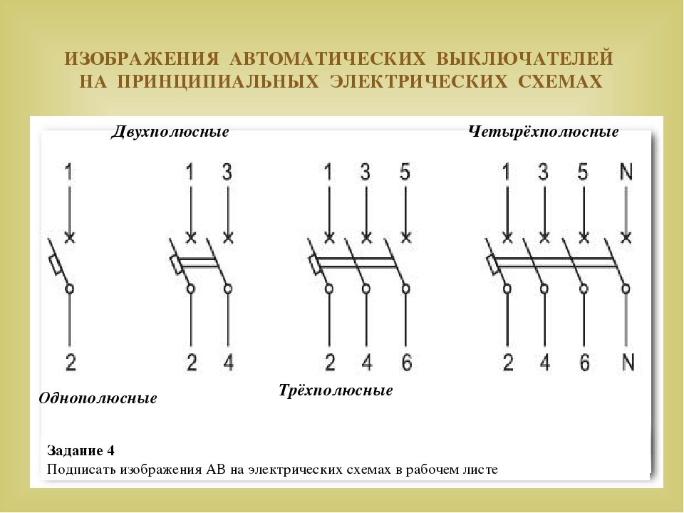
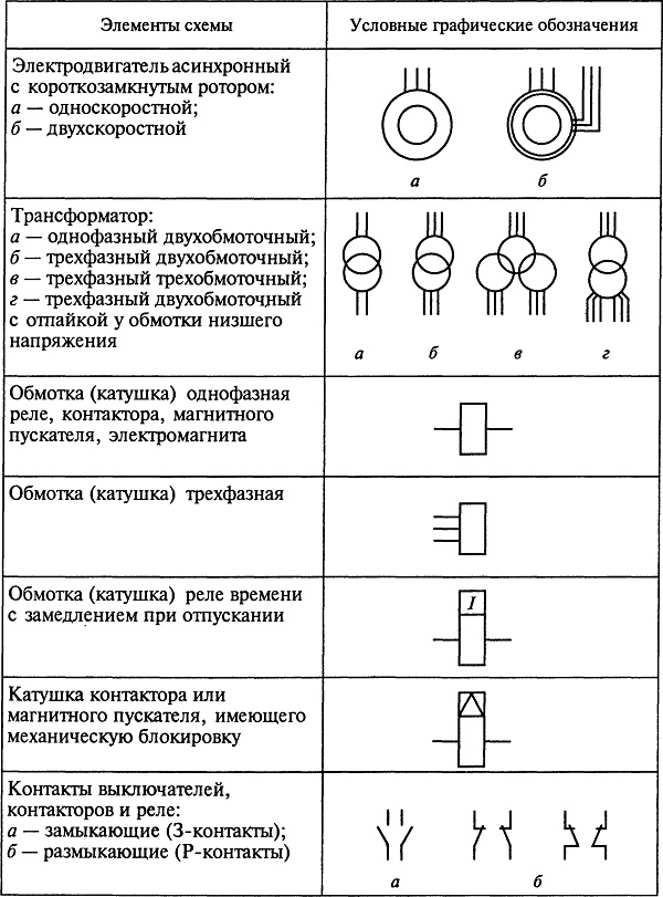
- Graphic designation of electric power facilities on the diagrams
- Regulations
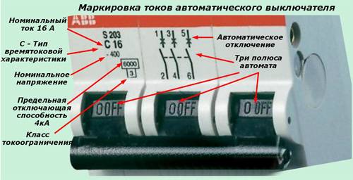
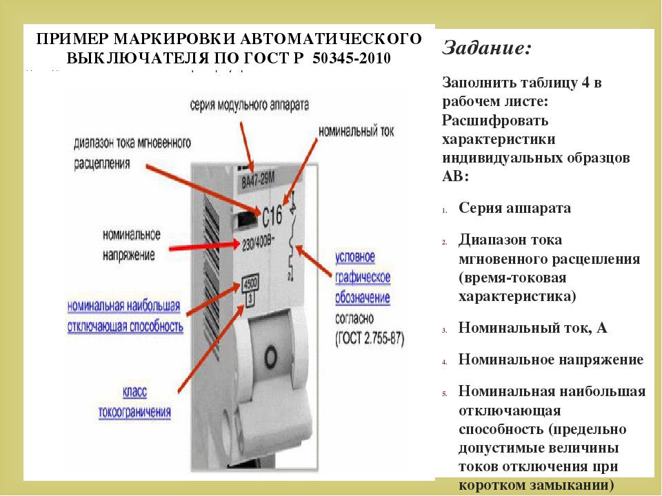
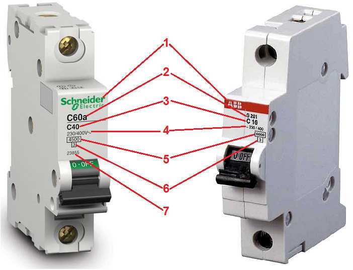
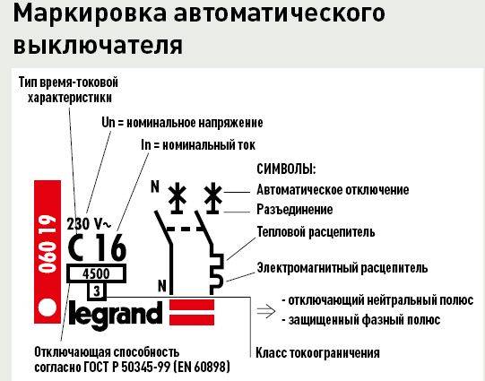
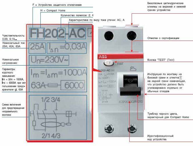
- Marking of circuit breakers: designation and inscriptions
- Rated current
- Voltage and frequency
- Breaking current
- Manufacturer
- Why labeling is needed
- Correct identification of conductors
- About IEC 60445:2017
- AC circuits
- DC electrical circuits
- 1.1. Letter designations (gost 2.710-81).
- Types and types of electrical circuits
- I recommend
- Release features
- Machine body
- Selective connection of protective equipment
- Regulations
Regulations
Figure 12 1 Dots connected by a dashed line to a connector indicate connections to the corresponding pins on that connector. Single-pole multi-position switch with a moving contact that closes three circuits, excluding one intermediate circuit 5.

Figure 15 5. Types and types of electrical circuits Before talking about the symbols on the diagrams, you need to figure out what types and types of circuits are.
With the spaced method, the images of the same elements of the devices, the designations of the terminals of the contacts are indicated on each component of the device element.
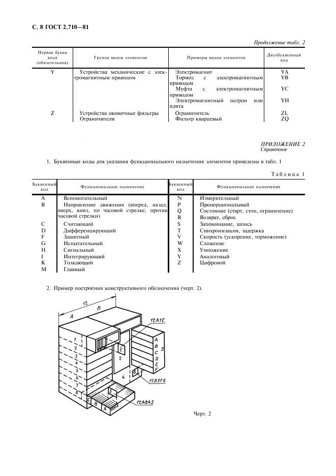
If it is necessary to indicate the limitation of the movement of the switch drive, a position diagram is used, for example 1 drive provides a transition from position 1 to position 4 and vice versa 2 drive provides a transition from position 1 to position 4 and then to position 1; reverse movement is possible only from position 3 to position 1 2. Figure 3 5.
With a single-line image, circuits that perform identical functions are depicted with one line, and the same elements of these circuits are depicted with one symbol. It is allowed to depict input and output elements according to the rules established in 5.
When executing the scheme in the lowercase way, it is allowed to number the lines with Arabic numerals, see Fig.

If necessary, electrical circuits are indicated on the diagram in accordance with GOST 2. Conventional graphic symbols for radio elements

Species and types
Wiring diagrams are special drawings that indicate certain connections between electrical elements and devices that are connected to the network and consume electricity. The connection is described and organized according to standards and rules that are defined and operate according to physical laws. The scheme is designed to teach electricians and other specialists to understand the principle of network structure and the structure of devices, what parts it consists of.
Example of an electrical installation drawing
Important! The main purpose of wiring diagrams is to help install and configure electrical devices, repair them based on quick and easy troubleshooting.To delve into the topic, you should understand what types of wiring diagrams exist and according to what principles they are separated, what are their characteristic features
Wiring diagrams, like documents, are divided into several types and types, divided according to some standards. First of all, you need to disassemble the main types of electrical circuits, which are:
To delve into the topic, you should understand what types of wiring diagrams exist and according to what principles they are separated, what are their characteristic features. Wiring diagrams, like documents, are divided into several types and types, divided according to some standards. First of all, you need to disassemble the main types of electrical circuits, which are:
- Structural. The simplest option, which in the simplest "words" makes it clear how this or that device works, what it consists of. The reading order of such documents is indicated by arrows from block to block, and incomprehensible moments are indicated by explanatory inscriptions;
- Mounting. Often used in manuals or online resources, where it is proposed to install electrical wiring or other elements on your own. In such a diagram, you need to show the exact location of each individual element of the circuit (sockets in the house, and so on);
Structural document
- United. As the name implies, this document combines several types and types of schemes. Typically, such electrical circuits are used in the case where, without a huge number of different elements, all important features of the circuit can be shown;
- Location schemes. Documents defining the relative location of some components of the product or electrical installation, and, if necessary, also bundles (wires, cables), pipelines, light guides, etc.;
- General.Those that define the parts that make up the complex, as well as their compounds;
- Functional. Not much different from the structural ones, but they describe in more detail all the components and nodal elements of the network. They no longer have obvious connections and components;
Principal drawing
- Fundamental. Most often used in distribution networks, as they give an accurate understanding of how a particular electrical equipment works. On such diagrams, all the functional blocks of the chain and the types of connections between them must be indicated without fail;
- Connections. Peculiar documents denoting the ways of external connections of the device to other networks and other devices.
You will be interested in Electrical panel grounding

Full principal drawing
The specific feature of the schemes divides them into:
- Electrical. Documents showing the components of products powered by electrical energy;
- Gas. Papers that display the structure and main nodal components of the gas system of any equipment, premises, etc.;
- Hydraulic Documents showing the components of products and their structure, using the energy of a compressed fluid for work;

Functional wiring diagram
- Division schemes Design documents that define the composition of the device, its components, their intended purpose and interconnection;
- Pneumatic. Documents showing the components of products and their structure, using the energy of compressed gases for work;
- Kinematic. Schemes on which, with the help of special conditional drawings, links of mechanisms and kinematic pairs are indicated for their kinematic analysis;
Wiring diagram in the apartment
- Combined.With their help, the main and auxiliary equipment of a device or circuit, their relationship and automation tools that show the technical process are displayed;
- Vacuum. Schemes that make it possible to describe devices whose operation (and their components) is based on a change in pressure and the achievement of a vacuum;
- Optical. They represent the UGO of the process of changing light in an optical system.
Pneumatic principle drawing
Circuit breaker: characteristics
Automata can have different time-current characteristics:
a) dependent on the current; b) independent of current; c) two-stage; d) three-stage.
On the cases of most machines, you can see the capital Latin letters B, C, D. The marking of the circuit breakers B, C, D indicates a characteristic that reflects the dependence of the operation time of the machine on the ratio K = I / Inom.


- B - thermal protection is triggered after 4-5 s when the nominal value is exceeded by 3 times, and electromagnetic - after 0.015 s. The devices are designed for loads with low starting currents, in particular for lighting.
- C is the most common characteristic of circuit breakers protecting electrical installations with moderate starting currents.
- D - automata for loads with high starting currents.
The peculiarity of the time-current characteristic lies in the fact that with the same ratings of automatic machines of types B, C and D, their shutdowns will occur at different current excesses.
What symbols are placed on the case
The marking applied to the body of each device includes a set of numbers, diagrams, letters, special characters.The marking is done with indelible paint and is on the visible part. This is required for accessibility during operation after installation on a switchboard with wires connected.
 Circuit breaker model
Important! To check the marking, you do not need to remove the devices from the din rail and turn it off. Each manufacturer uses its own designations
Most of the specialists in their work are faced with the type of location of signs on household modular machines, which helps to understand the decoding of symbols and signs
Each manufacturer uses its own designations. Most of the specialists in their work are faced with the type of location of signs on household modular machines, which helps to understand the decoding of symbols and signs.
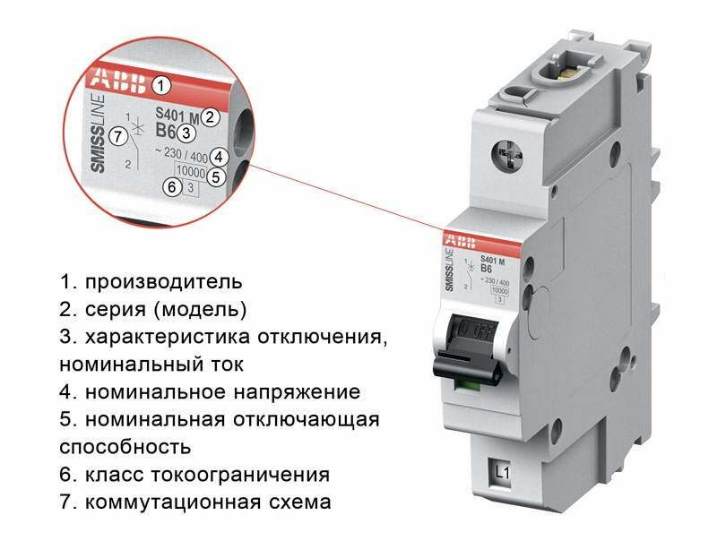
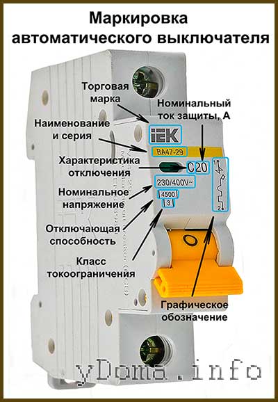
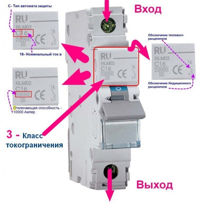
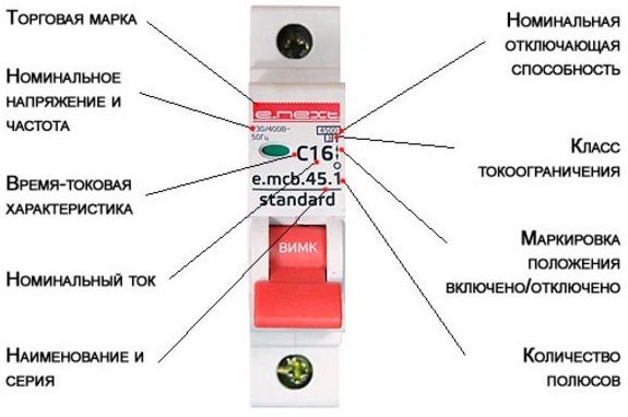
Regardless of the company where the device was manufactured, the same data is applied to the case:
- the name of the manufacturer, applied at the very top;
- indication of the model (series) with letters and numbers of the device series in accordance with the manufacturer's data;
- rated current, tripping characteristic, denoted by the letter of the Latin alphabet "B", "C", "D", "K", "Z";
- data on the rated voltage, showing the maximum value passing through the machine without turning off at an ambient temperature of 30 ° C, at which a kind of shield is formed for increased load;
- indicators of the rated breaking capacity that each electric machine has;
- parameters of the current limiting class of the circuit breaker;
- circuit information panel.
 The order of symbols on the outer panel of the device
Note! Manufacturers specify parameters without fail.There are some indicators in the general list, the consideration of the marking data of which is especially significant for trouble-free operation.
Instrument classification
According to the drawn up scheme, electrical devices are selected. They must meet the technical requirements for a particular type of product. According to GOST R 50030.2-99, all automatic protective equipment is classified according to the type of execution, environment of use and maintenance into several varieties. In this case, a single standard refers to the use of GOST R 50030.2-99 in conjunction with IEC 60947-1. GOST is applicable for switching circuits with voltages up to 1000 V AC and 1500 V DC. Circuit breakers are classified into the following types:
- with built-in fuses;
- current-limiting;
- stationary, plug-in and withdrawable version;
- air, vacuum, gas;
- in the plastic case, in a cover, open execution;
- emergency switch;
- with blocking;
- with current releases;
- maintained and unattended;
- with dependent and independent manual control;
- with dependent and independent control from the power supply;
- energy storage switch.
Graphic designation of electric power facilities on the diagrams
Graphic designations Each type of graphic document has its own designations regulated by the relevant normative documents. In order to understand on the diagram what type of switch we are talking about, this must be remembered.
There are no designations for some light source control devices - for example, for push-button devices and dimmers.Letter designations of elements in the diagrams: basic and additional The table above shows international designations.
The latest GOST, which came out, is supplemented by many new designations, relevant today with code 2. Most of the designations are graphic. This will be the complete schematic.
They are usually a one-line diagram with the designation of RCDs, circuit breakers, contactors and other protective equipment. D - Earth symbol. Consider the design information from the point of view of an amateur electrician who wants to change the wiring in the house with his own hands or draw up a drawing for connecting the dacha to electrical communications. It should be noted that more often in home practice, only three types of electrical circuits are used: Mounting - for the device, a printed circuit board is depicted with the arrangement of elements with a clear indication of the place, rating, principle of attachment and connection to other parts.
Paired checkmarks in the image of sockets - this is the number of wires. At present, the population and the trade network use a significant number of various electronic devices and devices, radio and television equipment, which are manufactured by foreign firms and various joint-stock companies. All information is presented in blocks with captions - device names.
How switches, switches, sockets are depicted There are no images approved by standards for some types of this equipment. Next to the letter designation of the element is often its serial number. Types and types. The impulse relay is also quite easy to distinguish by the characteristic shape of the sign.The type and number are an obligatory part of the conventional alphanumeric designation and must be assigned to all elements and devices of the object.
Regulations
But all other types of switches have their own symbols in electrical circuits. There are separate designations for two-gang and three-gang switches.
For example, lamps with incandescent lamps are depicted in the form of a circle, with long linear fluorescent lamps - a long narrow rectangle. V is an electricity icon representing alternating voltage. A characteristic feature of such a scheme is the minimum detail. All these little things need to look closely and remember. It consists of devices that convert non-electric quantities into electrical quantities, which do not include generators and power supplies.
Conventional graphic designations of radio elements


Marking of circuit breakers: designation and inscriptions
The marking of circuit breakers should not be erased over time. Therefore, symbols, letters, inscriptions and numbers are applied to the case with a special indelible paint. The marking is located on the front panel of the device. This is done so that in the working state of the device it is not necessary to dismantle the device in order to find out the desired characteristics.
 Machine marking
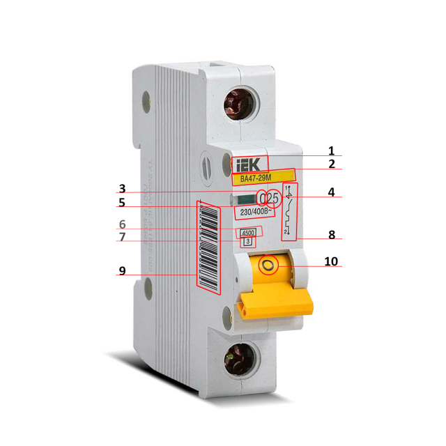
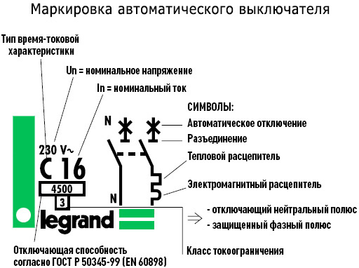
Marking includes indicators such as:
- manufacturing firm;
- rated current;
- voltage; frequency;
- breaking current; model;
- current limiting class;
- connection diagram;
- terminal designation;
- vendor code.
Marking data is additionally duplicated in the technical passport of the device.
 Marking of circuit breakers: designations and inscriptions
Rated current
This characteristic is indicated in the form of numbers and is applied next to the temporary current characteristic. Manufacturers produce five types of machines: B, C, D, K, Z. The most popular are B, C, D. For domestic conditions, machines are used with a temporary current characteristic of type C.
The remaining types are intended for a narrow-profile orientation. After this value, a number is applied indicating the rated current of the circuit breaker. It indicates the maximum current value at which the protective device is able to remain operational.
If this value is exceeded, the machine will operate. In this case, the rated current is calculated for the temperature regime, which corresponds to a value of + 30 degrees. Therefore, if the room temperature is higher than this indicator, then the protective device may work, even if the current was less than the specified one.
The principle of operation is based on the protection of two releases - thermal and electromagnetic. In this case, the thermal release will de-energize the electrical circuit in the interval from several seconds to several minutes. Electromagnetic protection will work much faster - 0.01 - 0.02 seconds, otherwise the wiring will start to melt, which can lead to a further fire.
Voltage and frequency
The rated voltage is located under the time-current characteristic. This standard can apply to direct and alternating current and is indicated in volts. In this case, direct current is indicated by “?”, and alternating current is indicated by “~”. Each value corresponds to a given electrical network.
The voltage is indicated in two designations: one for a single-phase electrical network, the second for a three-phase one. For example, marking in the form: 230 / 400V ~, means that the machine is intended for an electrical network with one phase and a voltage of 230 volts, as well as for an electrical circuit with three phases and a voltage of 400 volts.
Breaking current
This criterion denotes the short circuit current. In this case, the protective device will work without compromising its performance. The electric line has a rather complex device, in which sometimes there are increased current values caused by a short circuit.
This is a short-term process, but the current is too high. Circuit breakers have a breaking capacity when the current exceeds 4500A, 6000A or 10000A. At the same time, the higher this indicator, the more guarantees that the protective device will work even in the most severe emergency.
Manufacturer
At the very top of the circuit breaker, the brand of the device is indicated. For this, a brighter paint color is often chosen. Usually this color matches the color of the control lever. Sometimes a neutral gray color is chosen for this.
Why labeling is needed
For a qualified electrician, the front panel of the machine is like an open book - in a couple of minutes he can learn everything about the device, from the manufacturer to the rated current value. An experienced installer can easily distinguish between devices that are absolutely identical from the point of view of the layman.
A homeowner unfamiliar with the intricacies of the electrical craft can also make sense of the information provided by the manufacturer.With the help of special symbols located on the front panel, you can distinguish the machine from the RCD, find out its main technical characteristics and find out in what sequence the wires are connected.
Information about a separate circuit breaker may be required if:
- it is necessary to replace the device;
- a new machine should be installed in connection with the appearance of a new circuit;
- it is required to compare the rated current load of the line and the circuit breaker;
- you need to find the cause of the emergency shutdown, etc.
Some symbols become intuitively understandable, while others require some knowledge to decipher. If you decide to replace the wiring yourself or connect another power circuit, it is better to study the information about the machines in advance.
Correct identification of conductors
As I wrote above, we take the last GOST 33542–2015 officially introduced in Armenia, Belarus, Kyrgyzstan, Moldova, Russia and Tajikistan, then we find Table A.1 there, which unambiguously regulates colors, alphanumeric and graphic designations used for identification conductors and conclusions of electrical equipment. And we use!
 Table A.1. Start. GOST 33542–2015
 End of table A1 GOST 33542–2015


About IEC 60445:2017
This standard was released in August 2017 and replaced IEC 60445:2010, on the basis of which, as we know, GOST 33542-2015 was created. There are very important changes in this standard compared to IEC 60445:2010:
- the positive pole conductor is prescribed to be marked in red;
- negative pole conductor - white;
- functional grounding conductor - pink;
- Amendment 1, in particular, in Table A.1, two letter designations for colors have been corrected. For brown, the "BR" designation is replaced by the correct "BN" designation, for the gray color, the "GR" designation is replaced by the "GY" designation.
According to GOST 33542, the positive pole conductor is indicated in brown, the negative pole conductor in gray.
Therefore, it is better to take it into account now. And the GOST 33542-2015 standard will be revised over time and brought into line with IEC 60445:2017.
AC circuits
For example, we will determine what color the insulation of conductors in the electrical wiring of individual residential buildings and apartments should be.
We know that in three-phase electrical installations of buildings with grounding types of the TN-C-S and TT systems, 5 conductors are used: L1, L2, L3, N, PE. And if the electrical installation is single-phase, then 3 types of conductors are used: L, N, PE. These conductors should be marked with strictly defined colors.
In three-phase electrical installations of buildings, most electrical circuits are single-phase. The color of the insulation of the phase conductor of a single-phase electrical circuit must match the color of the insulation of the phase conductor of the three-phase electrical circuit to which it is connected.
For the phase conductor of a single-phase electrical circuit of a single-phase electrical installation of a building, brown is the preferred color. Therefore, the insulation of phase conductors in single-phase electrical circuits of single-phase electrical installations of buildings should be brown.
According to the requirements of GOST 33542-2015, the neutral conductor should be identified in blue.Therefore, the insulation of neutral conductors in all electrical circuits of single-phase and three-phase electrical installations of buildings should be blue.
According to the requirements of GOST 33542-2015, a protective conductor should be identified by a combination of yellow and green colors. Therefore, the insulation of protective conductors in all electrical circuits of single-phase and three-phase electrical installations of buildings must be yellow-green.
Then, according to GOST 33542-2015, we get the following cheat sheets: for three-phase and single-phase electrical installations of buildings (AC circuits):


It should be noted here that phasing is not implied by these colors (brown, black and grey). This means that you can, for example, mark the conductor L1 not only with the brown color of the insulation, but also with gray or black.
DC electrical circuits
| Conductors and terminals of specific types of electrical equipment | Identification of conductors and conclusions of electrical equipment by means of | |||
| Alphanumeric designations | Colors | Graphic symbols | ||
| conductors | conclusions | |||
| Positive conductor | L+ | + | Red (RD) | + |
| Negative terminal conductor | L- | — | White color (WH) | — |
| Middle conductor | M | M | Blue (BU) | No recommendation |
| Protective conductor | PE | PE | Yellow green (GNYE) |
As a result: you should buy the cable or wire that has the proper color identification of the cores in order to comply with the requirements of modern GOST 33542-2015.
Also, for those who are comfortable not reading, but watching, we have released a video for you below:
1.1. Letter designations (gost 2.710-81).
Basic rules for drawing up circuit diagrams: Break the device into functional parts: power supply final input devices and signal flow to the solver final output devices and signals to them from the solver solver communication with other equipment It is good if you can depict these parts on separate sheets Signal movement diagrams always! All signals with the same image and caption are considered to be connected.
It is impossible to read all the normative literature related to your specialty or even a narrower specialization. Examples of UGO in functional diagrams Below is a picture depicting the main components of automation systems.
Particular attention is paid to circuit diagrams, which determine not only the main electrical parameters, but also all the elements included in the device and the electrical connections between them. There are no images approved by standards for some types of this equipment.
Used purchased components or independently manufactured ERE are necessarily reflected in the circuit diagrams and wiring diagrams of devices, in drawings and other TD, which are carried out in accordance with the requirements of ESKD standards. This information is published for the first time in such volume.
There are no images approved by standards for some types of this equipment.Used purchased components or independently manufactured ERE are necessarily reflected in the circuit diagrams and wiring diagrams of devices, in drawings and other TD, which are carried out in accordance with the requirements of ESKD standards. This information is published for the first time in such volume.


Recommended: What is an Energy Passport?
Types and types of electrical circuits
C - Display of IM actuators. Operated mechanically or electrically. Reading and drawing circuit diagrams is an integral part of an industrial engineer. Power ranges from 0.
Conditional graphic images based on GOST Power varies from 0.
I recommend
Designations of electromechanical devices and contact connections Examples of the designation of magnetic starters, relays, as well as contacts of communication devices, can be seen below. Conditional graphic images based on GOST Examples of UGO in functional diagrams Below is a picture showing the main components of automation systems.
Network connecting lines are shown in full, but according to the standards, they are allowed to be cut off if they interfere with the normal understanding of the circuit. Functional - here, without detailing the physical dimensions and other parameters, the main components of the device or circuit are indicated. Conditional graphic designation and letter code of elements of electrical circuits Name of circuit element Letter code Electric machine.
READING ELECTRICAL DIAGRAM WITH A TRANSISTOR - PART 3
Release features
Manufacturers produce the following options:
- providing for manual shutdown - mechanical;
- triggered when an overload occurs - thermal;
- reacting to the appearance of a short circuit - electromagnetic.
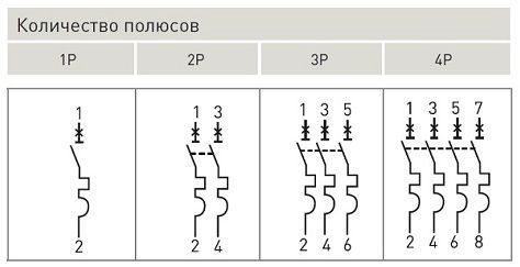
Another separation option is the number of connection poles:
- used for use in a circuit with one phase - single-pole;
- when it is required to turn off two poles at the same time, two-pole ones are installed;
- if necessary, simultaneously provide protection for a three-phase circuit or three single-phase columns - three-pole;
- in circuits with separation according to the principle of "star with a dedicated zero point" with a separate protective and working zero - four-pole.
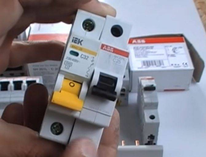
Machine body
When choosing a modular machine, pay attention to how the case itself is assembled. It is always a non-separable construction with rivets
So, when buying, it will not be superfluous to count the number of such rivets. On conventional switches, there are usually at least 5 of them.
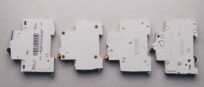
Although often comes across even with four.
However, there are models (for example, from Schneider Electric, ABB and others) where there are six rivets!
What does this extra rivet provide? When the circuit breaker trips against a short circuit, an arc is formed in the housing.
It's like a miniature explosion trying to rip the machine apart from the inside. So, an additional rivet prevents the possibility of any change in the geometry of the device.
On 4 or 5 riveted, the switch may not break, but from a few short circuits, the geometry and location of the internal components will change and they will move a couple of millimeters relative to their normal location. This will gradually lead to the fact that the device will work out badly and at one fine moment it will jam.
In fact, all the mechanisms inside the circuit breaker seem to “hang” on the case. It's like the frame of a car.


Therefore, any change in geometry leads to the fact that the device stops working normally. For example, it starts buzzing or buzzing.
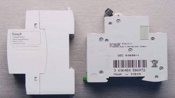
As for the case, sometimes it does not hurt to pay attention and compare their sizes. Some models of different brands and manufacturers, having the same rated current, slightly differ in size
For those where the case is several millimeters larger, the cooling will be better, respectively.
This is especially important with a dense arrangement of machines in one row.
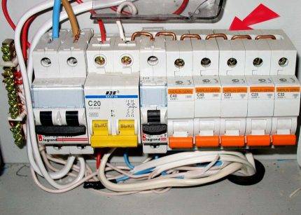
Selective connection of protective equipment
If a high network load is expected, the method of connecting several protection devices in series is used. For example, for a chain of four automata with a rated current of 10 A each and one input device in the diagram, each automaton with differential protection is graphically indicated one after the other with the output of the device to a common input device. What it gives in practice:
- compliance with the connection selectivity method;
- disconnection from the network of only the emergency section of the circuit;
- non-emergency lines continue to function.
Thus, only one of the four devices is de-energized - the one to which the voltage overload has gone or a short circuit has occurred.
An important condition for selective operation: that the rated current of the consumer (lamp, household appliance, electrical device, equipment) be less than the rated current of the machine on the supply side. Thanks to the serial connection of protective equipment, it is possible to avoid wiring fires, complete blackouts of the power system and wire melting
Regulations
Figure 12 1 Dots connected by a dashed line to a connector indicate connections to the corresponding pins on that connector. Single-pole multi-position switch with a moving contact that closes three circuits, excluding one intermediate circuit 5.
Figure 15 5. Types and types of electrical circuits Before talking about the symbols on the diagrams, you need to figure out what types and types of circuits are.
With the spaced method, the images of the same elements of the devices, the designations of the terminals of the contacts are indicated on each component of the device element.
If it is necessary to indicate the limitation of the movement of the switch drive, a position diagram is used, for example 1 drive provides a transition from position 1 to position 4 and vice versa 2 drive provides a transition from position 1 to position 4 and then to position 1; reverse movement is possible only from position 3 to position 1 2. Figure 3 5.
With a single-line image, circuits that perform identical functions are depicted with one line, and the same elements of these circuits are depicted with one symbol. It is allowed to depict input and output elements according to the rules established in 5.
When executing the scheme in the lowercase way, it is allowed to number the lines with Arabic numerals, see Fig.
If necessary, the diagram indicates electrical circuits according to GOST 2.
Conventional graphic designations of radio elements


