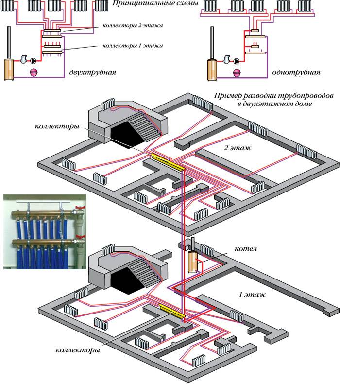
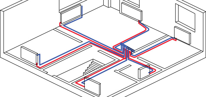
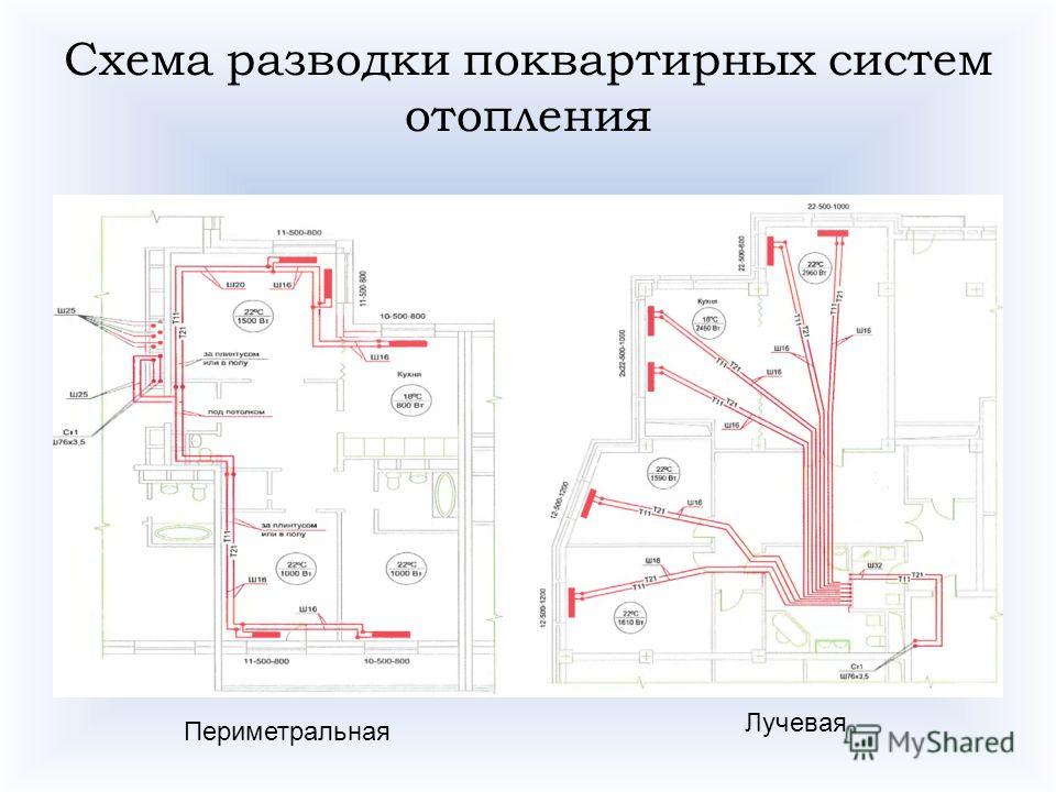
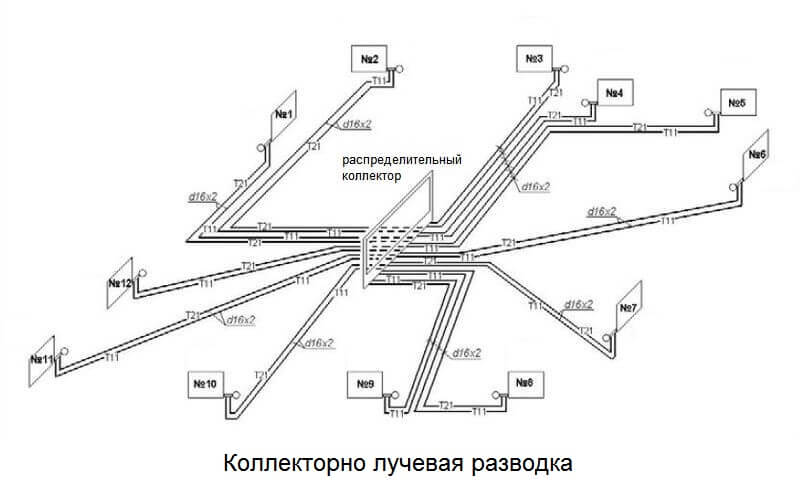
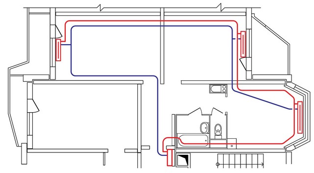
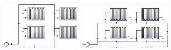
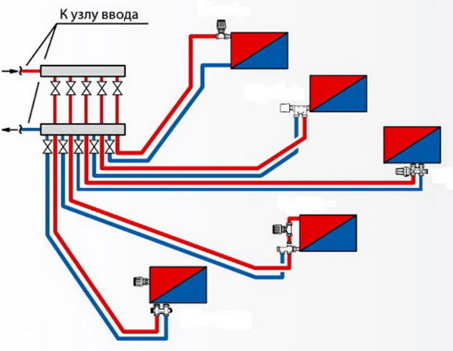
- Beam wiring connection diagram
- Method 1 with forced water circulation
- Method 2 with natural water circulation
- Benefits of horizontal wiring
- Two-pipe heating system with top wiring: get ready to hide the pipes
- Mounting Recommendations
- Beam wiring connection diagram
- preliminary stage
- Rules for installing beam wiring
- Radial piping layout: features
- Elements of the heating pipe wiring diagram
- Selection of inlet and outlet pipes
- Comparison with vertical heating system
- Choosing a heating scheme for a country house
- One-pipe scheme of heating systems
- Pros and cons of two-pipe wiring
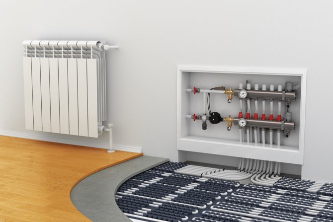
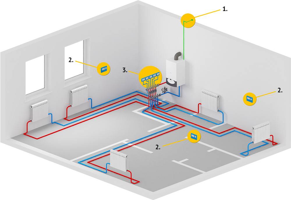
- How is the collector-beam heating distribution?
Beam wiring connection diagram
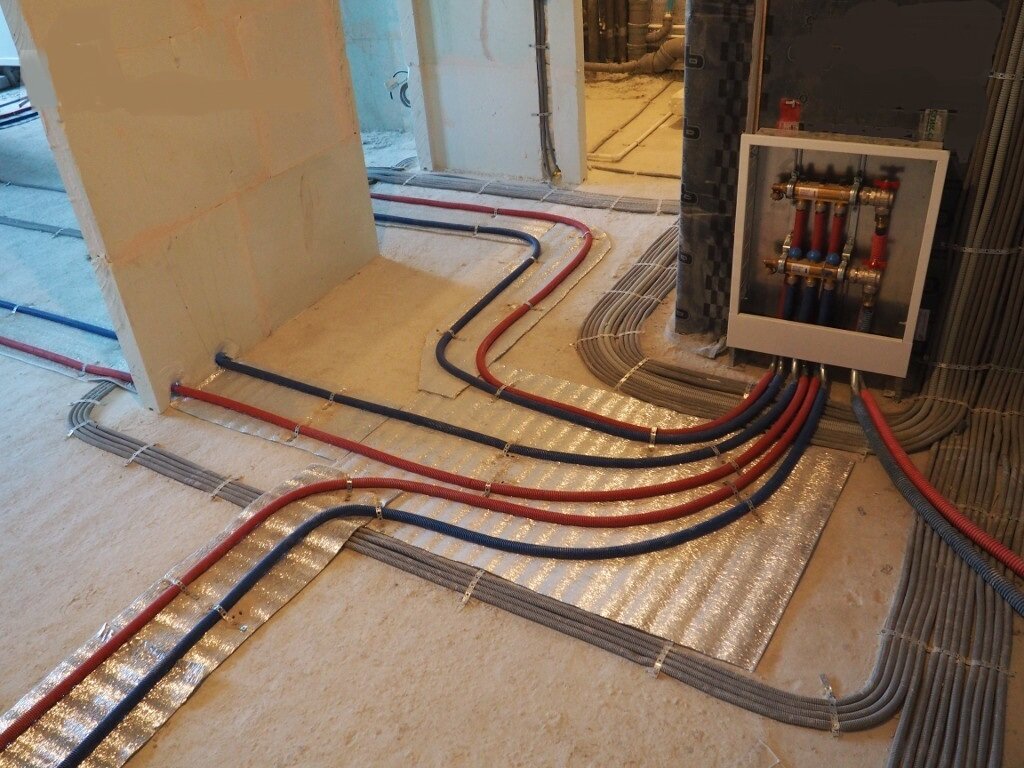
When choosing a scheme, preference is usually given to a floor-by-floor scheme. The network is carried out under a masking covering on the floor. The collector is usually mounted in a pre-prepared niche in the wall. An alternative is a special cabinet.
In most systems, it is required to mount a circulation pump, however, there are options when several of them are not required, or they are mounted alternately on each of the rings. An inlet and outlet container is attached to each element of the system.Then, pipes from the collectors are placed under the cement screed, and then they are connected to the heating element.
It is desirable that the duration of all pipes is approximately equal. Otherwise, it will be necessary to additionally supply the system with a circulation pump and sensors for temperature control. There are two main ways to organize heating: with and without forced circulation. It is worth painting each of them in more detail, with all their inherent features.
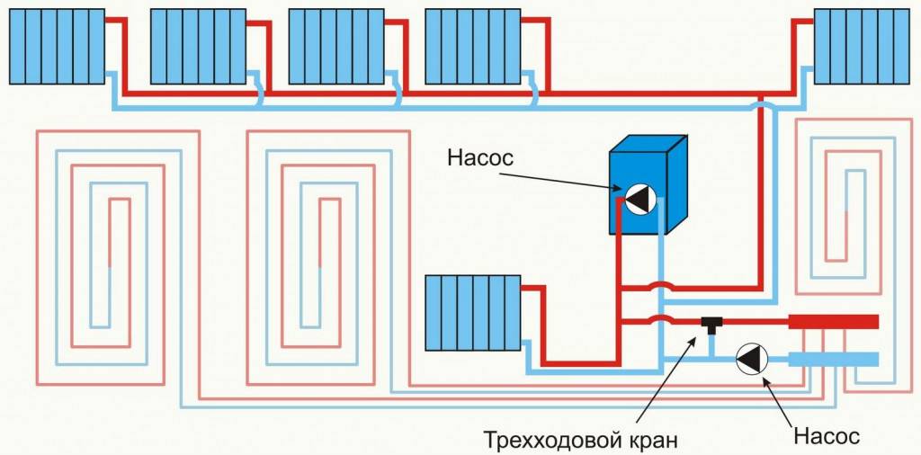
Method 1 with forced water circulation
This type of system, which is equipped with pumps for the forced movement of fluid, was previously considered extremely expensive. However, with the advent of cheap and reliable pumps, such heating with pumps has become increasingly used in apartment buildings and private homes.
The most important difference is that the coolant (water or antifreeze) circulates between the heating boiler and radiators not by gravity, temperature and pressure differences, but by using a special pump. Natural heating scheme
 Natural heating scheme
There are a number of positives though:
- The system can be mounted in a room of any complexity and geometry.
- You can install beam wiring in rooms with large areas.
- For laying, pipes of almost any diameter can be used, provided that they are located at right angles.
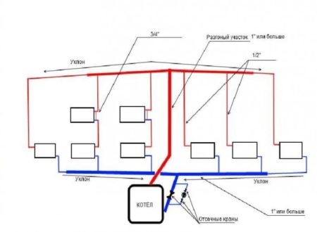
Method 2 with natural water circulation
In a system without the use of circulation pumps, the movement of fluid is provided by gravity. The hotter liquid has a lower density, due to which it moves up, then, over time, returns to the collector and batteries, and then to the radiators.
The installation has the following features:
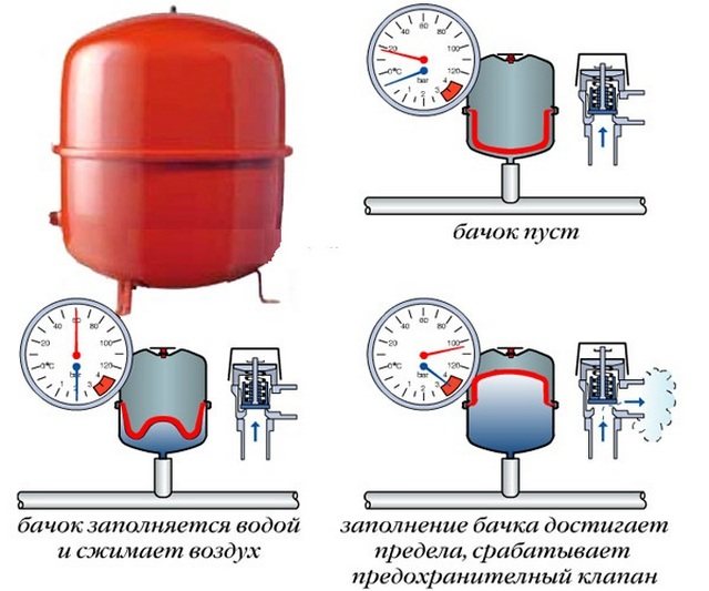
- During installation, it is required to provide a place for an open-type expansion tank, which must be placed in the highest place. It is required to compensate for the expansion of the coolant due to heating and does not allow the pressure to increase too much.
- This does not require the purchase and installation of circulation pumps, which reduces the estimate for work.
This type of heating does not require electrical energy, which is convenient for cottages and other country houses.
Benefits of horizontal wiring
By itself, the idea of separated heating provides many operational advantages, which are expressed in ease of maintenance, more accurate accounting of water consumption data, etc. without affecting the operation of the general circuits. The independence of horizontal wiring in the heating systems of an apartment building allows, if necessary, to replace damaged pipes in individual sections. The possibility of hidden laying of communications is also preserved, which is not always allowed when installing vertical systems.
Two-pipe heating system with top wiring: get ready to hide the pipes
When designing small cottages on one floor, a scheme is advisable in which the coolant is supplied from above to the radiators. From the boiler, hot liquid rises up the supply riser and then descends through pipes to the batteries. And the “return” is carried out at the bottom through all the radiators.
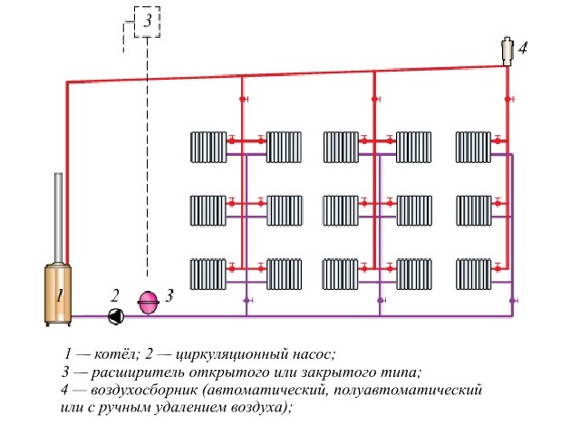
Upper wiring of a two-pipe system with forced (closed type expander is installed at any point) or natural (open type expander is installed from above) circulation.
The biggest drawback of the upper wiring is the unpresentable appearance of the supply line located under the ceiling and the cost of its “masking”. Hide the pipe in several ways:
- under suspended ceilings or ceiling trim;
- in ceiling niches, drywall boxes;
- in the attic. With this option, the cost of pipe insulation increases significantly;
- vertical sections are usually hidden in artificial ledges imitating columns.
If the circulation of the liquid occurs due to gravity, it will be necessary to insulate the pipes in the attic in any case: at the highest point of the system there must be an expansion tank. It is needed to compensate for the increase in the volume of the hot coolant.


- restriction of the minimum diameter of pipes associated with a high rate of resistance to natural circulation;
- most modern radiators are not suitable due to the small section;
- pipe slopes must be strictly maintained, otherwise the heating will not work correctly.
Mounting Recommendations
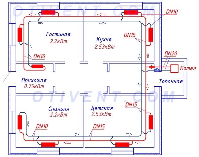
First of all, it is necessary to correctly determine the diameters of pipelines, especially for highways, here one cannot do without hydraulic calculation. It is a little easier with radial branches to radiators, their size can be taken according to this principle:
- for batteries up to 1.5 kW, pipe 16 x 2 mm;
- for a radiator with a power over 1.5 kW, a pipe 20 x 2 mm.
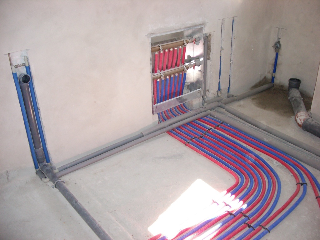
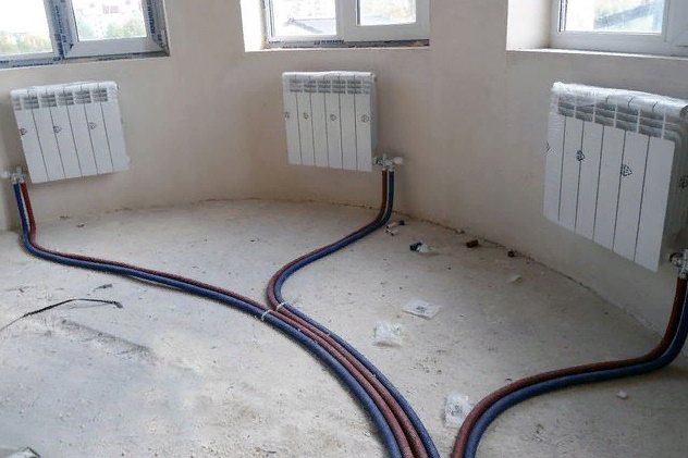
When wiring in the floor, all connections must be insulated, otherwise you will heat the screed sections, and the batteries will be cold.Do not scatter the pipes at random, arguing that they will still be flooded with mortar and no mess will be visible. This is a mistake, the branches must be laid carefully, distributing them in pairs, and at the end put down only noticeable marks for you in those places where the pipes lie. Subsequently, this will help to quickly find them in the event of an accident.
Do-it-yourself installation in a one-story house is relatively simple. Choose the optimal placement for a cabinet with a collector (ideally - in a wall niche), measure the distances and purchase pipes, install radiators. Balancing fittings do not need to be installed anywhere, only ball valves on batteries. By the way, if possible, vertical sections of pipes coming out of the floor can be hidden in the walls. Then the connections to the heating devices will not be visible at all.
In a house with two or more floors, each branch from the riser install shut-off and control valves. A ball valve is installed on the supply pipeline, and a balancing valve is installed on the return pipeline. This will balance the entire system hydraulically, as well as cut off floors from heating if necessary.
Beam wiring connection diagram
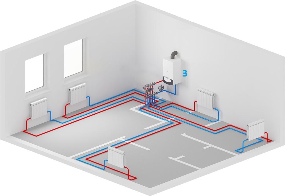
When choosing a heating scheme, in most cases they stop at the radial floor distribution of the pipeline. All pipes are hidden from view in the thickness of the floor. Collector - the main distribution body is installed in a niche of the wall fence, often in a special cabinet located in the center of the house / apartment.
In the vast majority of cases, the implementation of beam wiring requires the presence of a circulation pump, and sometimes several, installed on each ring or branch.Its necessity is described above. The beam wiring of the heating system assembly is most often performed on the basis of one- and two-pipe installation, almost completely replacing the tee type of connection.
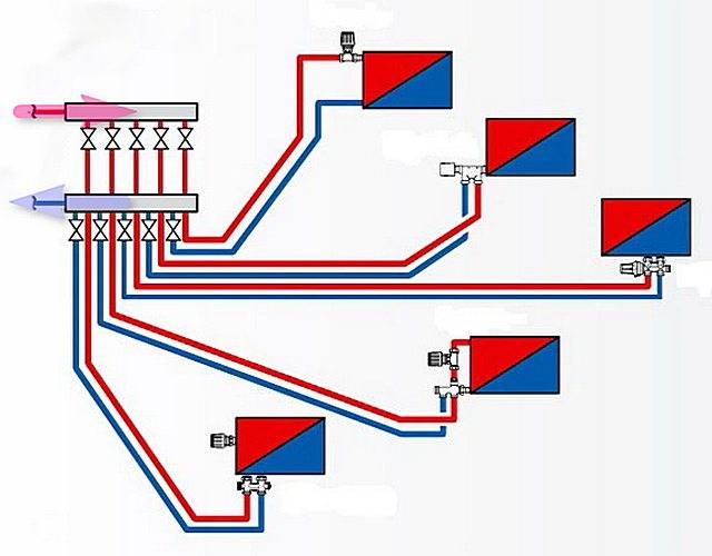
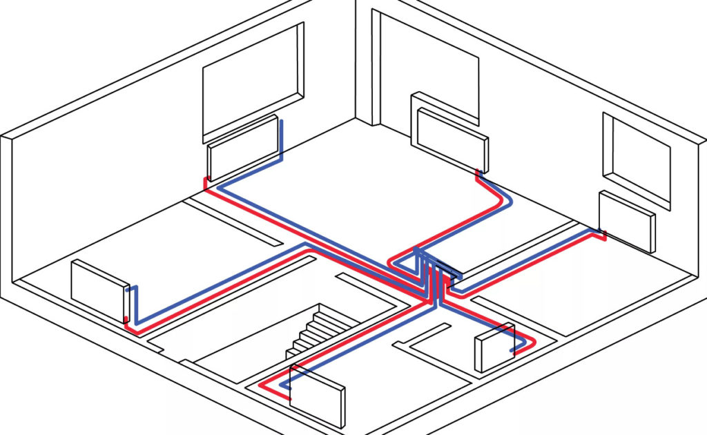
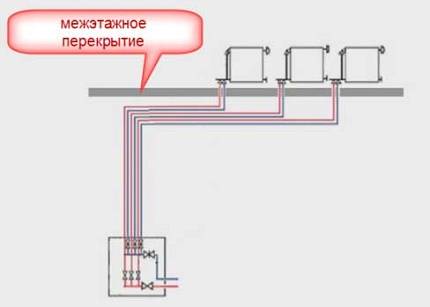
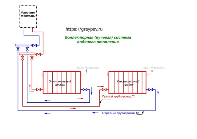
This is simplified beam wiring diagram, in which each radiator is connected to a manifold connector for direct and reverse flow of coolant
On each floor, near the riser of the two-pipe system, the supply and return manifolds are mounted. Under the floor, pipes from both collectors run in the wall or under the floor and connect to each radiator within the floor.
Each of the contours should have approximately the same length. If this cannot be achieved, then each ring must be equipped with its own circulation pump and automatic temperature control.
In this case, the change in the temperature regime will be completely independent on each circuit and will not affect each other. Because the pipeline will be under the screed, each radiator must be equipped with an air valve. The air vent can also be placed on the manifold.
preliminary stage
Before starting work, the task of the owner is to correctly select all the components and locations of the equipment, namely:
- determine the location of the radiators;
- choose the type of radiators based on pressure indicators and the type of coolant, as well as determine the number of sections or the area of \u200b\u200bpanels (calculate heat losses and calculate the heat output required for high-quality heating of each room);
- schematically depict the location of radiators and pipeline routes, not forgetting about the rest of the elements of the heating system (boiler, collectors, pump, etc.);
- make a paper list of all items and make purchases. In order not to make a mistake in the calculation, you can invite a specialist.
So, in order to proceed to the next stage, it is necessary to take into account the rules for mounting the beam system
Rules for installing beam wiring
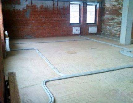
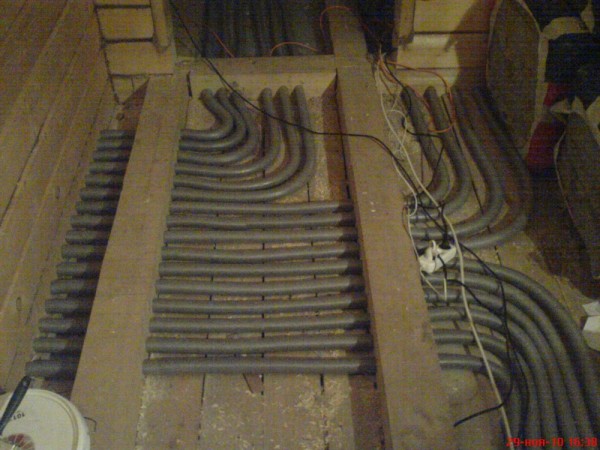
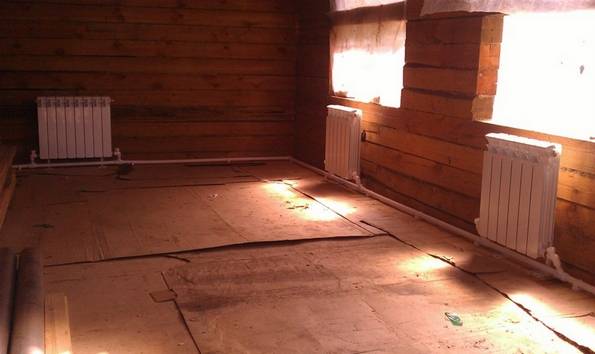
If you have chosen to lay pipes under the floor, follow a few rules that will help to avoid heat loss and freezing of the coolant. There should be enough space between the rough and finish floor (more on this later in the description).
When installing pipes in the floor, it is important to take into account several requirements, one of which is the presence of sufficient space between the finishing and subfloor
AT as subfloor may be a concrete foundation slab. A layer of insulation is first laid on it, then a pipeline is arranged. If pipes are laid without a heat-insulating substrate, then the water in these areas can freeze, losing a lot of heat.


As for pipes, it is better to opt for polyethylene or metal-plastic models, which are highly flexible. The polypropylene pipeline does not bend well, therefore it is not suitable for beam wiring.
The pipeline must be attached to the base so that it does not float during pouring with a finishing layer of screed. You can fix it with mounting tape, plastic clamps or other available methods.
The pipe under the screed must be insulated to reduce heat loss to a minimum, and on the ground floor it is imperative to lay a layer of thermal insulation
Then, around the pipeline, we lay the insulation with a layer of 50 mm from foam or polystyrene. We also fasten the insulation to the base of the floor using dowels-nails.The final step is to fill the solution with a layer of 5-7 cm, which will serve as the base of the finishing floor. Any floor covering can already be laid on this surface.
If pipes are laid on the second floor and above, then the installation of a thermal insulation layer is optional.
Remember one important rule, there should not be any connections in the sections of the pipeline under the floor
If there is a circulation pump of sufficient power and performance, the collector is sometimes placed one floor lower relative to the level of the radiators.
If the collector is located at the lower level (basement), then you need to take into account several rules for the correct piping from the comb to the radiators, which are located on the next level
Radial piping layout: features
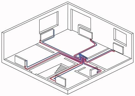
The most optimal beam distribution of the heating system is suitable for those cases where the house has several floors or there are a large number of rooms. Thus, it is possible to significantly increase the efficiency of all equipment, guarantee high-quality heat transfer, and eliminate unnecessary heat losses.
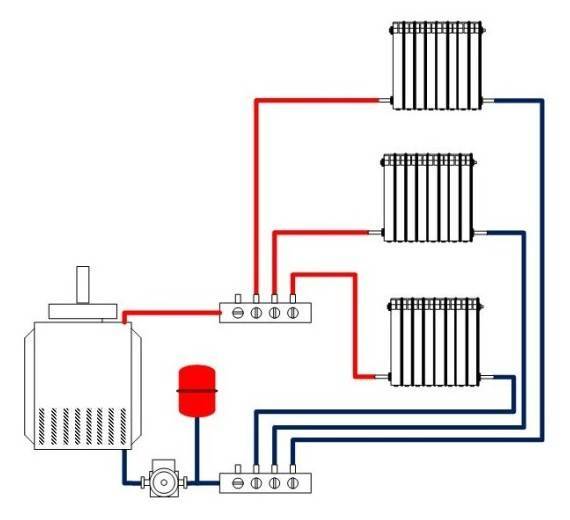
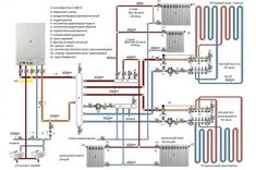
One of options for arranging a collector circuit pipeline
The principle of operation of the heating circuit, made according to the collector circuit, is quite simple, but at the same time, there are some features in it. So, for example, a radiant heating scheme involves the installation of several collectors on each floor of a building, and from them the organization of piping, direct and reverse supply of coolant. As a rule, the instruction for such a wiring diagram implies the installation of all elements in a cement screed.
Elements of the heating pipe wiring diagram
Modern radiant heating is a whole structure, which consists of several main elements:
Boiler. Starting point, the unit from which the coolant is supplied to pipelines and radiators. The power of the equipment must necessarily correspond to the amount of heat consumed by heating;
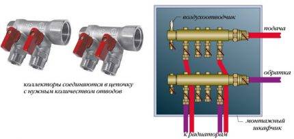
Collector for the heating circuit
When choosing a circulation pump for a collector piping scheme (this is also required by the instructions), it is imperative to take into account a lot of parameters, ranging from the height and length of the pipelines (these elements create hydraulic resistance) to the materials of the radiators.
The power of the pump is not the main parameters (it only determines the amount of energy consumed) - attention should be paid to the speed of pumping the liquid. This parameter shows how much coolant the circulation pump can transfer in a certain unit of time;
Installation of plastic pipes in the heating collector circuit
Collectors for such systems can additionally be equipped with a variety of thermostatic or shut-off and control elements, thanks to which it is possible to provide a certain coolant flow in each of the branches (beams) of the system. In addition, the additional installation of automatic air purifiers and thermometers allows you to set up a more efficient operation of the system at no extra cost.


One of the options for distributing plastic pipes in a collector circuit
The selection of one or another type of collectors (and they are presented on the domestic market in a large assortment) is made according to the number of connected radiators or heating circuits.In addition, all combs also differ in the materials from which they are made - these can be polymeric materials, steel or brass;
Cabinets. Beam wiring of the heating system requires the hiding of all elements (distribution manifold, pipelines, valves) in special collector cabinets. Such designs are quite simple, but at the same time functional and practical. They can be both external and built into the walls.
Selection of inlet and outlet pipes
Before starting any work on the arrangement of the heating system, it is important to determine the main parameters of the pipes. To begin with, it should be noted that the outlets at the boiler, the supply line, as well as the entrance at the collector must have the same dimensions
Based on these properties, pipe diameters are also selected, and, if necessary, special adapters are used.
Selection of coolant from the tank and its distribution through the pipeline
The materials of the pipes for supplying and discharging the coolant can be very different, but it is best to use plastic products. It's all about their practicality, ease of installation work and accessibility.
Comparison with vertical heating system
Find the best solution in choosing heating system will allow comparison considered option with a traditional vertical wiring model. One of the main differences can be called power, that is, the amount of heat transfer, which can also be expressed as efficiency. According to this indicator, vertical heating systems win. The horizontal model, due to the more rigid separation of the branches, does not allow them to fully transfer thermal energy to each other, while the risers themselves help to retain heat in the circuit.There is also a difference in systems management. Vertical wiring is more focused on external control by service providers, however, on the part of user regulation, it has a less developed toolkit.
Choosing a heating scheme for a country house
According to our expert Vladimir Sukhorukov, the rating of closed-loop systems is as follows:
- Dead-end two-pipe.
- Collector.
- Two-pipe passing.
- Single pipe.
A single-pipe version of the heating network is perfect for a small house with an area of \u200b\u200beach floor up to 70 m². The Tichelman loop is appropriate for long branches that do not cross doors, for example, heating the upper floors of a building. How to choose the right system for houses of various shapes and heights, see the video:
Watch this video on YouTube
Regarding the selection of pipe diameters and installation, we will give a few recommendations:
- If the area of \u200b\u200bthe dwelling does not exceed 200 m², it is not necessary to make calculations - use the advice of an expert on the video or take the cross section of pipelines according to the diagrams above.
- When you need to “hang” more than six radiators on a dead-end wiring branch, increase the pipe diameter by 1 standard size - instead of DN15 (20 x 2 mm), take DN20 (25 x 2.5 mm) and lay up to the fifth battery. Then lead the lines with a smaller section indicated initially (DN15).
- In a building under construction, it is better to do beam wiring and choose radiators with a bottom connection. Underground highways must be insulated and protected with plastic corrugation at the intersection of the walls.
- If you don’t know how to properly solder polypropylene, then it’s better not to mess with PPR pipes.Mount heating from cross-linked polyethylene or metal-plastic on compression or press fittings.
- Do not lay pipe joints in walls or screed, so as not to have problems with leaks in the future.
One-pipe scheme of heating systems
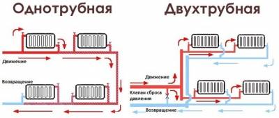
One-pipe heating system: vertical and horizontal wiring.
In a single-pipe scheme of heating systems, the hot coolant is supplied (supply) to the radiator and the cooled coolant is removed (return) through one pipe. All devices are connected in series with respect to the direction of movement of the coolant. Therefore, the temperature of the coolant at the inlet to each subsequent radiator in the riser is significantly reduced after the removal of heat from the previous radiator. Accordingly, the heat transfer of radiators decreases with distance from the first device.


Such schemes are mainly used in old central heating systems of multi-storey buildings and in autonomous systems of the gravitational type (natural circulation of the heat carrier) in private residential buildings. The main defining disadvantage of a single-pipe system is the impossibility of independently adjusting the heat transfer of each radiator individually.
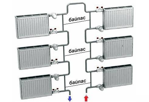
To eliminate this drawback, it is possible to use a single-pipe circuit with a bypass (a jumper between the supply and return), but in this circuit, the first radiator on the branch will always be the hottest, and the last the coldest.
In multi-storey buildings, a vertical single-pipe heating system is used.
In multi-storey buildings, the use of such a scheme allows you to save on the length and cost of supply networks.As a rule, the heating system is made in the form of vertical risers passing through all floors of the building. The heat dissipation of radiators is calculated during system design and cannot be adjusted using radiator valves or other control valves. With modern requirements for comfortable indoor conditions, this scheme for connecting water heating devices does not meet the requirements of residents of apartments located on different floors, but connected to the same riser of the heating system. Heat consumers are forced to “tolerate” overheating or underheating of the air temperature during the transitional autumn and spring periods.
Single-pipe heating in a private house.
In private houses, a single-pipe scheme is used in gravitational heating networks, in which hot water is circulated due to the differential density of the heated and cooled coolants. Therefore, such systems are called natural. The main advantage of this system is energy independence. When, for example, in the absence of a circulation pump connected to the power supply networks in the system and, in the event of power outages, the heating system continues to function.
The main disadvantage of the gravitational one-pipe connection scheme is the uneven distribution of the coolant temperature over the radiators. The first radiators on the branch will be the hottest, and as you move away from the heat source, the temperature will drop. The metal consumption of gravity systems is always higher than that of forced systems due to the larger diameter of pipelines.
Video about the device of a single-pipe heating scheme in an apartment building:
Pros and cons of two-pipe wiring
For ease of perception, we have combined the advantages and disadvantages of all the above systems into one section. First, let's list the key positives:
- The only advantage of gravity over other schemes is independence from electricity. Condition: you need to select a non-volatile boiler and make the piping without connecting to the house electrical network.
- The shoulder (dead-end) system is a worthy alternative to the "Leningrad" and other single-pipe wiring. The main advantages are versatility and simplicity, thanks to which the two-pipe heating scheme of a house of 100-200 m² is easily mounted by hand.
- The main trump cards of the Tichelman loop are hydraulic balance and the ability to provide a large number of radiators with coolant.
- Collector wiring is the best solution for hidden pipe laying and full automation of heating operation.
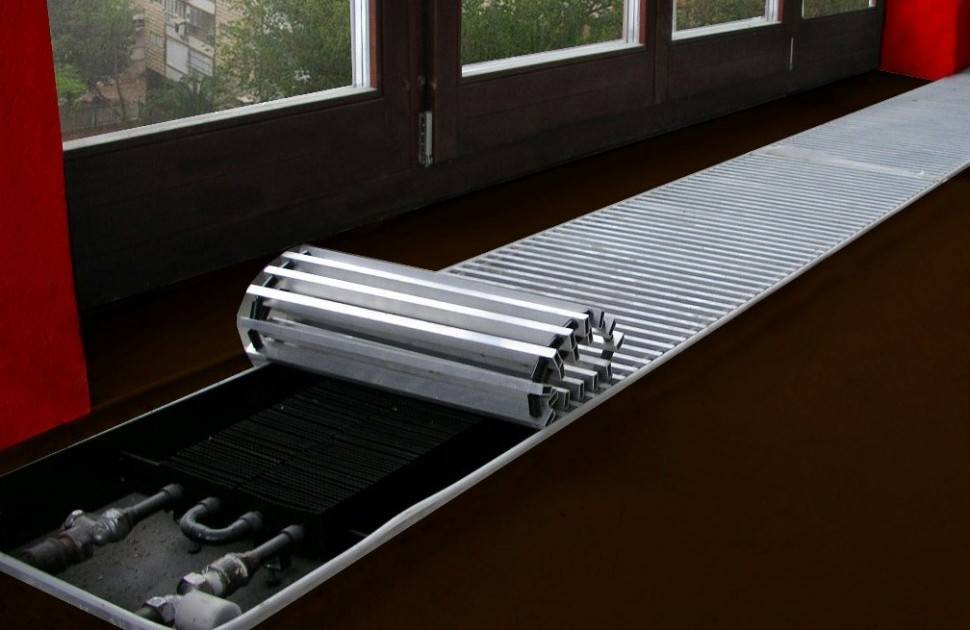
The best way to hide pipes is to lay them under the floor screed
- small sections of distributing pipes;
- flexibility in terms of laying, that is, the lines can run along various routes - in floors, along and inside walls, under ceilings;
- various plastic or metal pipes are suitable for installation: polypropylene, cross-linked polyethylene, metal-plastic, copper and corrugated stainless steel;
- all 2-pipe networks lend themselves well to balancing and thermal regulation.
To hide pipe connections, you need to cut grooves in the wall
We note a secondary plus of gravity wiring - the ease of filling and removing air without the use of valves and taps (although it is easier to vent the system with them). Water is slowly supplied through the fitting at the lowest point, air is gradually forced out of the pipelines into an open-type expansion tank.
Now for the major drawbacks:
- The scheme with natural water movement is cumbersome and expensive. You will need pipes with an inner diameter of 25 ... 50 mm, mounted with a large slope, ideally steel. Hidden laying is very difficult - most of the elements will be in sight.
- No significant disadvantages were found in the installation and operation of dead-end branches. If the arms are very different in length and number of batteries, balance is restored by deep balancing.
- Tichelman's ring wiring lines always cross doorways. You have to make bypass loops, where air can subsequently accumulate.
- Beam-type wiring requires financial costs for equipment - manifolds with valves and rotameters, plus automation equipment. An alternative is to assemble a comb from polypropylene or bronze tees with your own hands.
How is the collector-beam heating distribution?
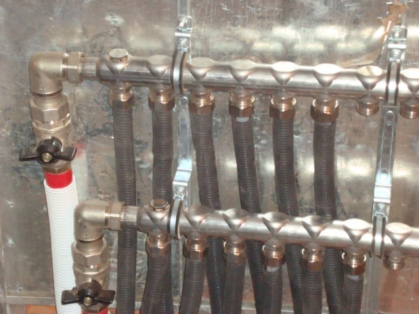
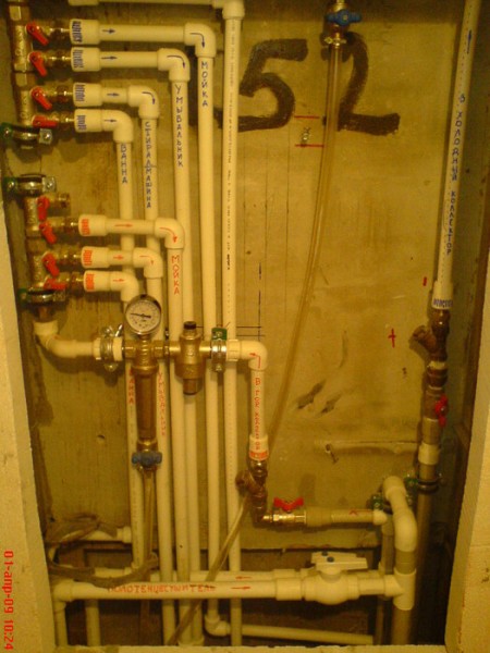
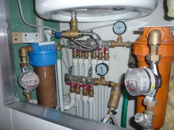
At the forefront (or rather, in a certain place where it will not interfere), a heating collector is installed. It can be installed open or in a cabinet. Now there are a lot of options on the market from simple overhead to built-in with mother-of-pearl locks))).


The heating collector must be taken specifically for heating. An ordinary water collector will not work. It should have special valves and valves, which will further contribute to balancing the system. And with the help of them, you can block the branch to a specific radiator and carry out its removal or replacement. All this will get rid of unnecessary additional taps on the radiators.
The collector unit is connected to the heating boiler.To do this, it is necessary to lay a sufficiently thick pipe of at least 25 mm (for cross-linked polyethylene) or 32 mm (for polypropylene). Therefore, the choice of a place for a collector is also determined by the possibility of attracting such a route to it. A dirt filter is installed on this route. And the collector itself is cut off from the boiler circuit with additional taps in order to be able to replace the boiler without draining the entire coolant.

Two pipes come to each heating radiator from the collector. Their diameter is usually some 16 mm (for cross-linked polyethylene). This diameter is enough even for the most powerful radiator. These pipes must be insulated or minimally corrugated.
When beaming pipes, their small diameter of 16 mm facilitates laying in the floor screed.