- The order and specifics of the connection
- Limit switch - device device and principle of operation
- Purpose of the limit switch
- The device and operation of the switch KV-1, KV-2
- Limit switch KV-04
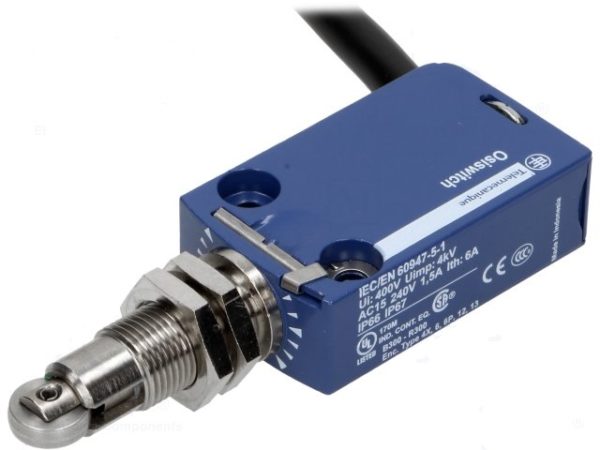
- Non-contact limit switches
- Kinds
- How to connect a limit switch
- For front door
- For wardrobe
- For sliding doors
- For swing doors
- For gate
- For auto
- Magnetic devices
- reed switches
- Inductive Models
- Limit switch marking
- Features of the design of the limit switch with a roller
- Impulse relays
- Applications
- Areas of use
- Features of the design of the limit switch with a roller
- EKM device
- For example, consider connecting the electric drive of the GZ-A gate valve
- Scheme of connecting a pass-through switch from 2 places
- Segment-leading manufacturers
- Advantages of contactless models
The order and specifics of the connection
Wiring diagram
Although the limit microswitch itself is quite simple, it can be used in technological equipment saturated with electronics. It follows from this that it should be connected by a specialist with experience, well versed in the switching circuits of electronic components.
A typical example of such a connection is the installation of a mechanical switch in a typical 3D printer, during which it is required to fix the extreme position of the carriage. The mounted switch has 3 contacts with the following designations: COM, NO, NC. In the open state, there is a voltage of +5 Volts on the first and third terminals (while the second contact is reliably grounded). When the movable carriage reaches the end position between COM and NC, a connection appears, after which it is fixed and rebounded by about 2 mm.
Such a sensor is connected by means of two conductors in red and black insulation. When installing another type of switch (with an indicator), a more complex circuit is used, in which another conductor is provided - in green insulation. When the micro-switches of the push type are activated, the LED lights up in the printers and a characteristic click is heard. Its connector, located on the switching board, has special designations:
- the red wire is marked as V (+5 Volts) and is used to connect the appropriate voltage;
- the black conductor is connected to the G-point (or ground);
- S (Signal) is selected for the green bus.
The same signs are also on the connector of the optical limit switch, which fixes the position of the carriage more accurately.
It works completely silently, the achievement of the extreme position is accompanied by LED indication. Its disadvantages include the possibility of failures with strong dust or exposure to direct sunlight.
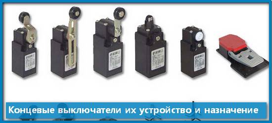
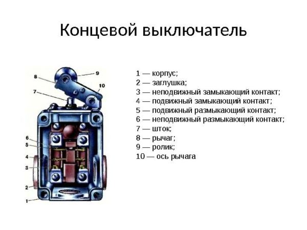
Limit switch - device device and principle of operation
A limit switch is used to control and limit the movement of various mechanisms.
It must have the following characteristics: reliability of operation, safety for people and devices, high MTBF.
There are a large number of varieties of these switches: mechanical, magnetic, inductive. Each group is divided into subgroups. It all depends on where this or that device will be used.
Purpose of the limit switch
Switching of electrical circuits of alternating current 220V can be carried out using limit switches.
The action of the devices and their operation is due to the contact contact of the end parts of the moving elements of the pneumatic drive, consisting of on-off type pipeline fittings.
In addition, they can be used as limit switches that act as a position sensor in other devices, in systems that are used in industrial automation.
The device and operation of the switch KV-1, KV-2
The principle of operation of devices KV-1 (single-position, two-channel), KV-2 (two-position, single-channel) linear movement - limit switches is to use a permanent magnet printed circuit board with two reed switches, they are used as the main switching electric circuit - elements.
In addition to the board in the "limit switch" housing, the limit switch device contains a terminal block, in the main (first) housing there are two blind holes in which the rod goes, for KV-02 - 2 rods. A permanent magnet, a magnetic circuit and a return spring are attached to the rod.
The action of the rod is reciprocating, with its help the magnet moves and closes - opens the contacts.
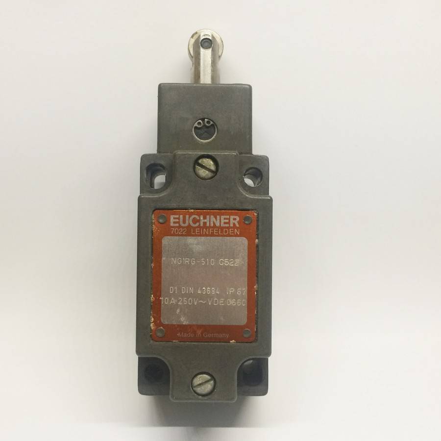
Rice. No. 1. Photo of the limit switch KV-01, KV-02.
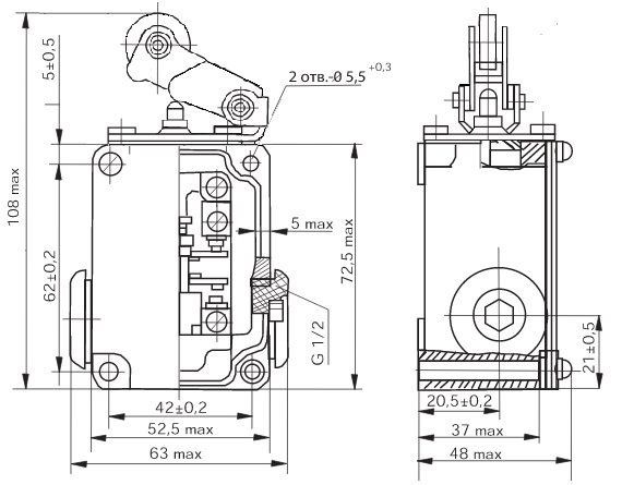
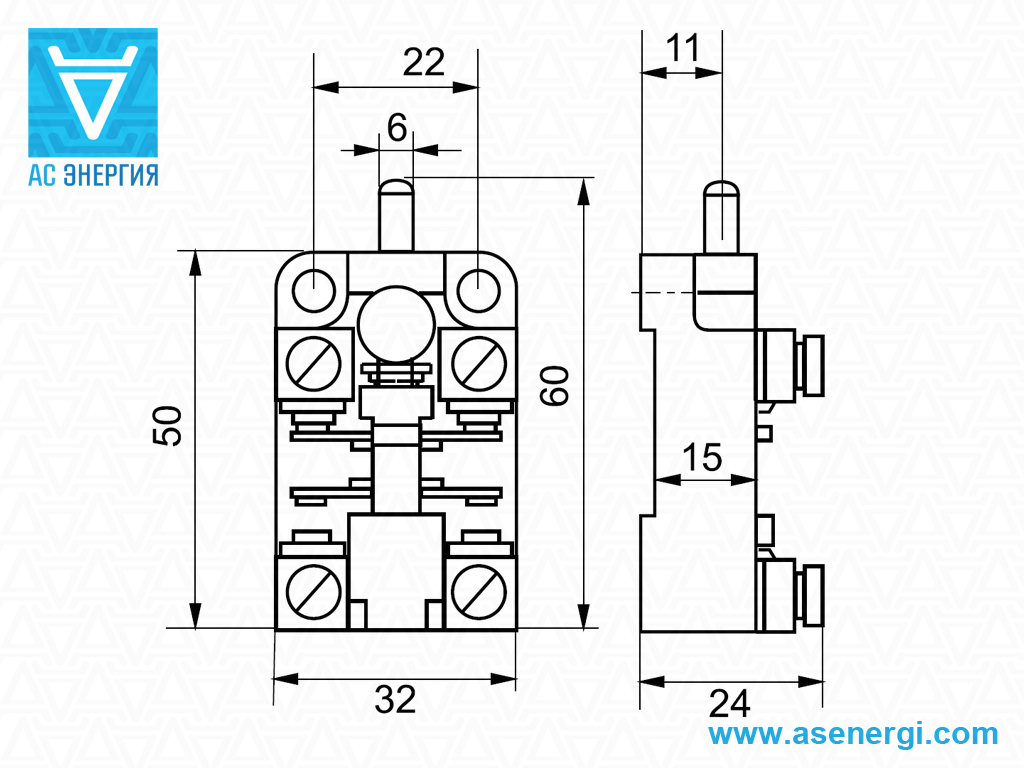
Rice. Number 3.A drawing of the KV-1 limit switch indicating the overall and installation dimensions of the KV-01 and with the location in the cable entry structure.
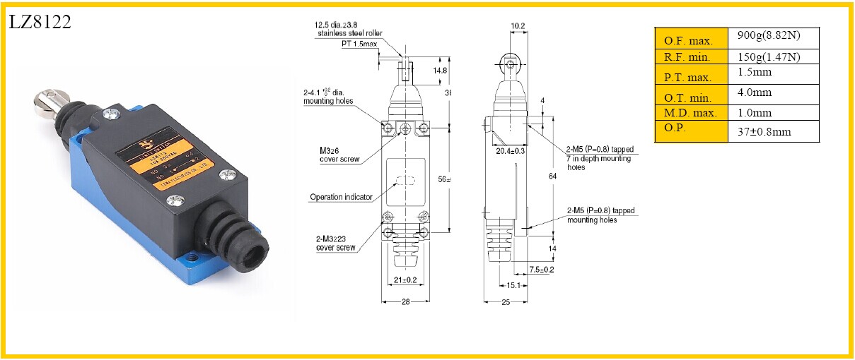
Limit switch KV-04
The design of the KV-04 (two-position, single-channel, rotary) is basically similar to the previous devices. Unlike a single-position switch, it is complicated by the presence of a rotary lever, with which you can adjust the angle of rotation of the axis in the direction and counterclockwise. Thus, the reed switches are switched.
Rice. No. 4. Dimensional drawing of the switch KV-04
The adjustment takes place by changing the cams located on the washer, they act on the levers, when turned, the magnet moves, switching the reed switch.
Fig. No. 5. Schematic diagram of connection of the limit switch KV-04.


Rice. No. 6. Photo limit switch KV-04.
Non-contact limit switches
Limit or as they are also called travel, switches are non-contact, they carry out work based on the use of electromagnetic relays, as well as on the use of logical elements, work occurs without influence from the moving part of the device.
Non-contact limit switches are divided into two main types according to the principle of operation and the effect on the sensing element:
- mechanical impact.
- Parametric action, due to changes in the physical parameters of the transducer.
Parametric switches are divided into the following types:
- Inductive.
- Capacitive.
- Optical.
The connection of such devices is based on the use of 2-wire and 3-wire circuits. Power in the case of a 3-wire circuit comes through a special wire.
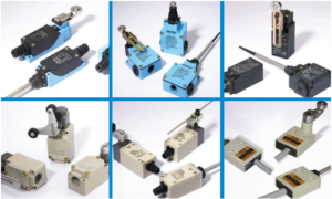
Rice. No. 7.Non-contact limit switches (sensors).
Non-contact limit switches are subject to increased requirements for operational reliability, because such devices have to work in difficult conditions.
The location of these devices is located in the working area of machines and units, where they can be affected by significant high temperatures, can be hit and work under the influence of strong vibration.
They can also be under the influence of a strong magnetic field, they can be affected by various, including aggressive liquids and pollution.
Of particular importance is the high requirement for higher switching frequencies, especially in demanding applications such as automated machine lines, complex transport systems, metallurgy and foundries.
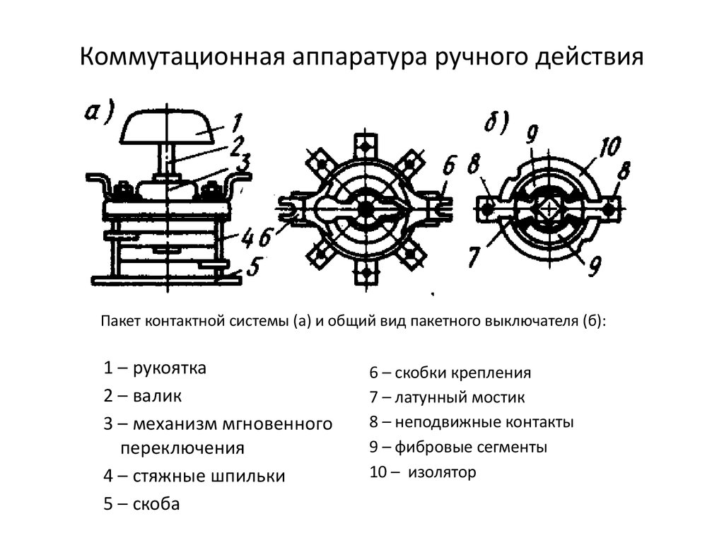
Kinds
There are one-, two- and three-pole devices. The first two are designed for a load of 10-25 A, the allowable voltage is 220V. Three-pole devices can withstand a voltage of 380 V, while the load is somewhat reduced, it should not be more than 15 A.
Available in open, closed and fully sealed bags. There is no protective sheath in open-type circuit breakers. These packets are used to switch connections at safe voltage and indoors only. Closed devices are equipped with a plastic or metal housing. The terminals of these devices are closed from touch, and the device itself is perfectly protected from dirt and dust. Closed models are allowed to be installed outside the shield cabinet.
Sealed electrical appliances are enclosed in a non-combustible, shockproof, sealed plastic shell. A high level of protection allows you to mount devices in an open space. Some models are equipped with a transparent window through which you can monitor the status of contacts.
The popularity of package devices is gradually decreasing, but the production of such electrical appliances has not been stopped. Reliability, availability, and quick response help bags to remain in demand.
How to connect a limit switch
Before connecting the wires of the devices, it is necessary to turn off the electricity by switching in the shield. The installation of a limit switch requires careful adjustment of the operation.
To mount and connect the device, you need to fix the door with four self-tapping screws so that when it is closed, it presses on the limit switch button, and when it is open, the button is released. Connect the electrical circuits of the switch through the terminal block to a current of 220 V.
The limit switch in the electrical circuit must be the last element before the supply wire.
For front door
The limit switch on the front door is designed to ensure the functioning of the alarm system and the activation of the light in the apartment. It is more expedient to install non-contact sensors, because they take up little space and are quite reliable in operation.
Before installation, the position of the door and the limit switch must be taken into account. To connect the device, electrical circuits must be carried out on a non-combustible base for fire-fighting purposes. Work on the installation and adjust the switch should be a certified tool.


For wardrobe
The purpose of installing limit switches is to provide automatic lighting when the door is opened. First you need to lay electrical wiring to the cabinet. At the ends of sliding doors, it is required to install a door mechanical switch with a voltage of 220 volts. All wires must be laid in protected trays. Then the marking of the installation of the lamp and the end ones is made. After installation, the wires are connected and the operation of the limit switches is adjusted.
For sliding doors
For sliding doors, the installation of the limit switch is carried out in the same way as for furniture, but an ultrasonic sensor must be used.
For swing doors
For swing doors, a mechanical pushbutton type 4313WD must be used. Wires to the installation site are laid in trays. Adjusting the operation of the switch with your own hands must be done carefully without damaging it, since the working stroke of the rod is 3.5 mm.
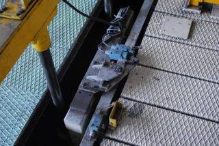
For gate
Roller mechanical limit switches are used for automatic opening and closing of the gate. Installation is possible only on sliding gates, because they have less backlash in the mechanical part than swing gates. At the ends of the gate, it is necessary to install limit switches, which will be connected to the opening drive motor and to the starter.
When installing the switch devices on the gate, the conductors to the electric motor are brought in a corrugated pipe, and the switch is selected in a moisture-proof housing.
For auto
The installation of limit switches in the car is necessary for the functioning of the alarm and lighting. A simple push button switch is used on the hood and trunk doors. For interior doors - contactless.After connecting the limit switches for the car, you should adjust the sensitivity of the security system.
Loading …
Magnetic devices
reed switches
Limit switches that respond to a magnetic field are assembled on the basis of a reed switch. A reed switch is a device that has a pair, or more, contacts made of a special ferromagnetic alloy.
When a magnet is brought up, they close (or open). The advantage of this design is the absence of mechanical contact, which significantly increases the service life of such a limit switch.
For its installation, it is important not to forget about the magnet, since there will be no reaction to ordinary iron. The scope of this model is very wide. In fact, this is a microswitch that can be discreetly placed anywhere.
For example, it can be connected to a car alarm to discourage those who like to drain gasoline.
In fact, this is a microswitch that can be discreetly placed anywhere. For example, it can be connected to a car alarm to discourage those who like to drain gasoline.
The principle of operation is simple. When the door is closed, the magnetic field acts on the microswitch. The circuit is closed, everything is fine. When the gas tank cap is opened, the magnet moves away, the contact breaks and the alarm turns on.
Inductive Models
As a rule, these are also not separate devices, but blocks: there can be several pairs of contacts in one housing. The sensors are available in various designs: fastening with bolts, nuts, and glue. The sizes are also very different: from large to microswitches. Such limit switches require a supply voltage. They are used as limiters for the movement of various mechanisms.
A limit switch of this type has replaced mechanical models for a long time. It is more convenient, as it does not require direct touching. In addition, having an inductance coil in its design, such a limit switch reacts to metal, which means that there is no need to install a separate magnet.
As you can see, the limit switches have a fairly wide range. For the most part, these are blocks containing contacts in various designs, which makes the limit switches more versatile. Large, robust housings are essential for heavy mechanical loads. Microswitches are widely used both at home and in production. Everyone can find the right model for themselves.
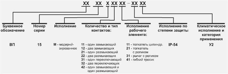
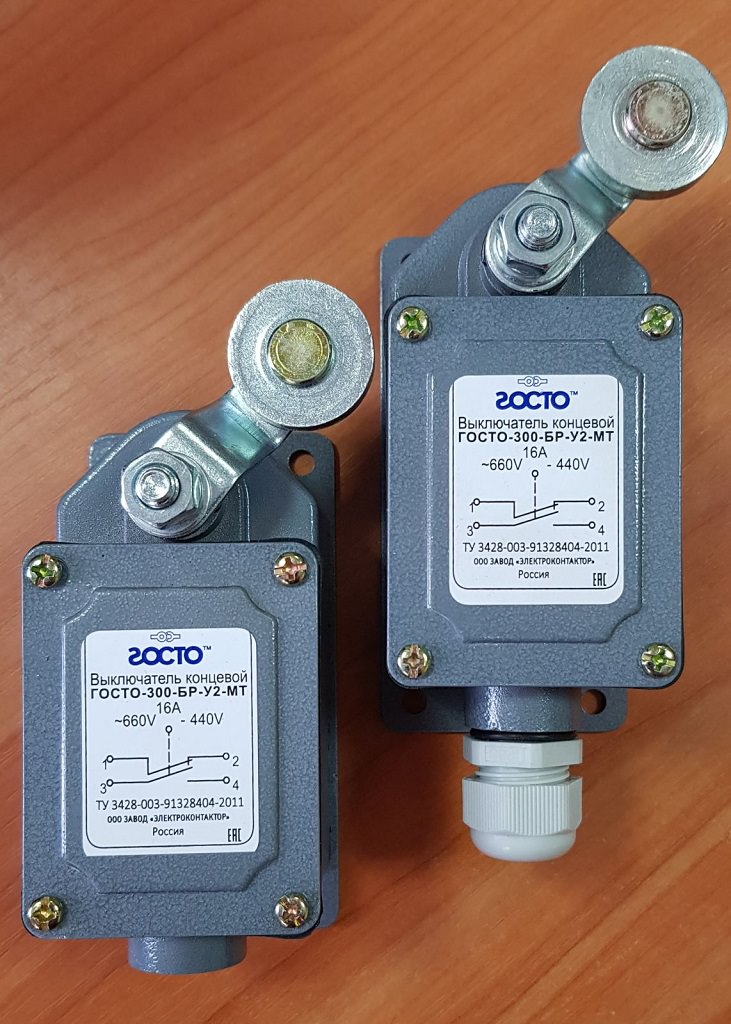
Limit switch marking
Microswitches and microswitches, regardless of their characteristics, have a specific marking. After decoding it, it is possible to obtain all the information about each model of the limit switch. If an entry like "VU222M" is found on it, this indicates a switch of the corresponding series. As an example, let's decipher the marking of a widely used product of the brand VP 15M4221-54U2. It means that in its design there is one moving element of the 15 series, as well as one make and break contact.
 Limit switch marking
All switching elements of this series are controlled by a pusher with a roller built into the housing.
The degree of protection on the drive side of the design corresponds to IP54, and the “U” icon means climatic version. The number 2 following it is the product placement category, which corresponds to TU U 31.2-25019584-005.
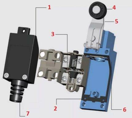
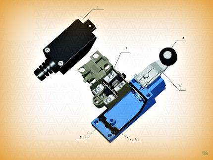
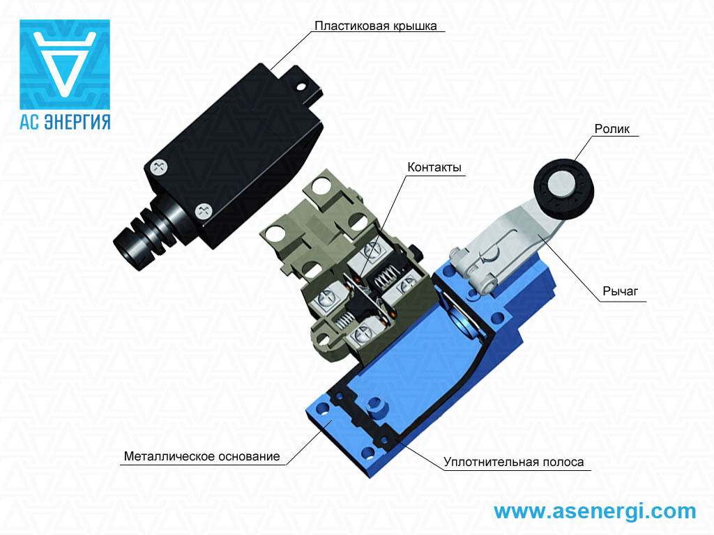
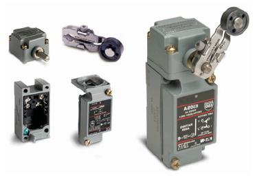
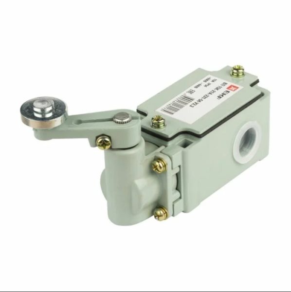
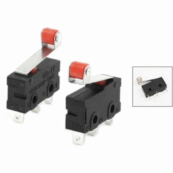
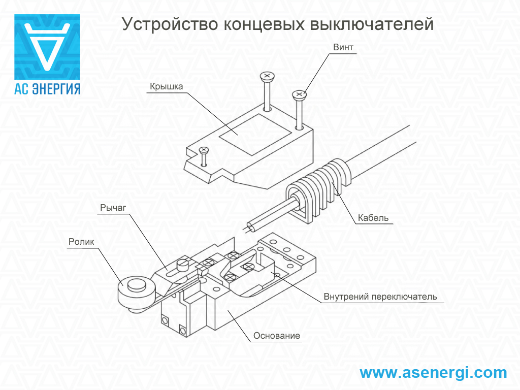
Features of the design of the limit switch with a roller
A design of this type is one of the options for implementing a button type, only with a modified button. Installing the roller allows you to significantly expand the functionality of the device. If the button can be pressed only in the axial direction, then the roller will respond to any action - axial or tangential, the main thing is that the vector of this action is in the plane of rotation.

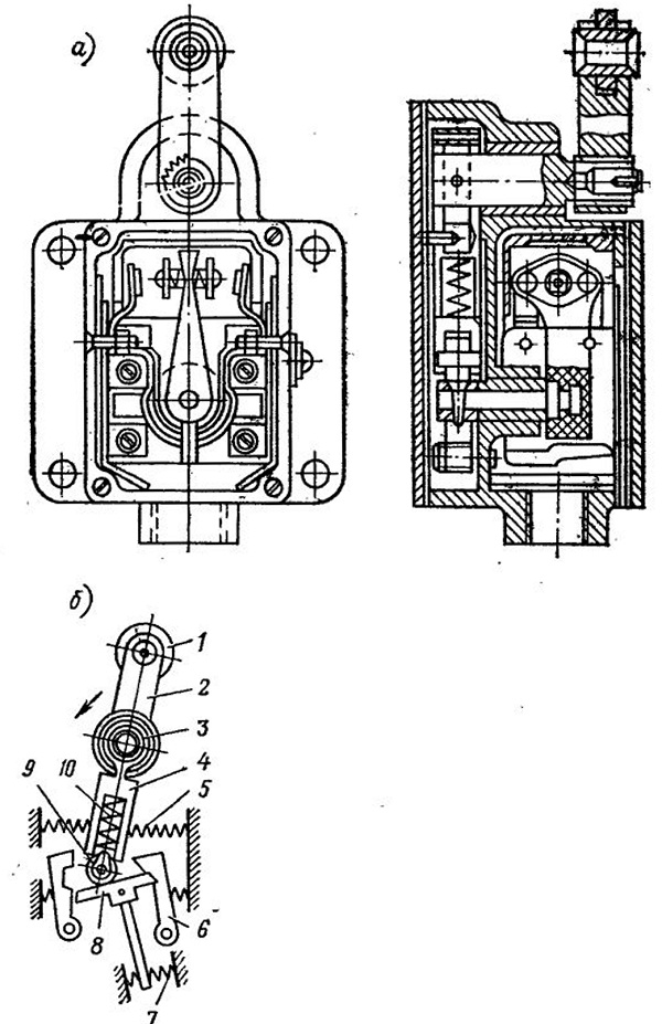

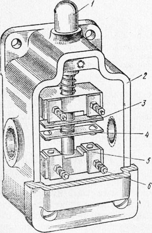


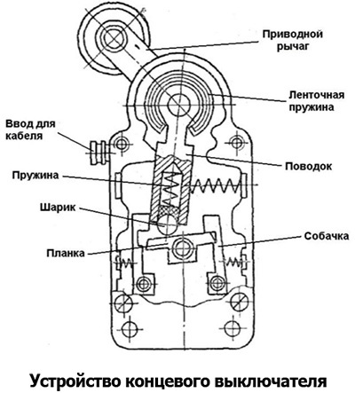
Limit switch device
The spring-loaded rod on which the roller is mounted is a movable element on which two pairs of contacts are installed - normally closed and normally open. When pressed, one pair opens and the other closes. This design is commonly called the plunger type KV.
Plunger-roller limit switch
It is used mainly on lifting mechanisms, devices with vertical movement of moving parts. For horizontal elements, it is used to a limited extent, only when the accuracy of the impact and the limited force are guaranteed.
There are lever roller designs. The roller is mounted on a rotary lever, which, turning, closes the contact group inside the housing. This design is convenient in mechanisms where it is impossible to accurately adjust the force and range of contact with the moving element due to large inertia, vibration, and uneven movement.
Lever limit switch
The danger of destruction of such a device with too sharp or intense contact is much less than when using a plunger-type limit switch.They are usually installed on massive and large moving elements with increased inertia - elevators, escalators, trolleys, mine lifts, sliding gates of hangars, etc. Sometimes such structures are called limit switches, since they have the ability to be triggered by the action of moving elements passing without stopping.
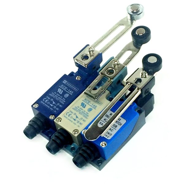
There are KV models with adjustable lever length. They allow changing the length of the roller support, which expands the possibilities and scope of the device.
Roller limit switch with adjustable lever
There are also designs where the lever is added as an additional element that increases safety. If you unscrew it, the HF takes the form of a conventional push-button device. Most microswitches are of this design.
Microswitches
Impulse relays
Lighting control using impulse relays is a completely different approach than those described above. Pulse relays are often used where it is necessary to control the light from two or more places (to infinity), not limited to the load of lines and the area of \u200b\u200bthe premises. The main difference is that this method is controlled using push-button switches (buttons) and an impulse relay mounted on a DIN rail in the electrical panel. There are also relays that can be installed in junction boxes, sockets or fixtures, but these are used much less often.
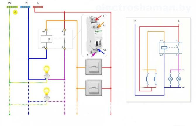
The principle of operation of a pulse (bistable) relay is quite simple. When voltage is applied to the relay coil (by pressing one of the control buttons), an impulse occurs at which the contact closes and after a second impulse it opens.This is achieved by the fact that in such relays the armature has two stable positions, which change with each new short-term supply of the coil and remain stationary after the absence of contacts (i.e. the relay does not require constant power to hold the contacts).
As you can see in the diagram, to connect the relay, you need to run two cables to the electrical panel where the relay will be installed. A cable from a group of buttons and a cable from a group of lamps, which makes it easy to change to any other way of lighting control in the future when needed.
In the future, new lighting schemes will definitely be added, in the wake of new technologies and trends.
blog comments powered by DISQUS back to top
Applications
For each type of limit switch, it is common to use it in various fields of activity. According to their application, they can be divided into:
- Protective, which are installed in order to protect the mechanism or personnel from rash actions. For example, a cage that lowers people into a mine will not start moving until all its doors are closed, thereby ensuring the safety of miners.
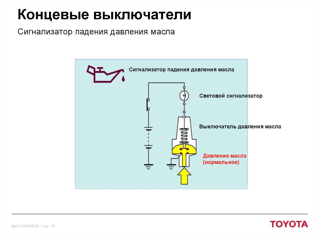
- Functional. They regularly turn lights or other electrical machinery on or off. The most obvious example of such a device known to everyone is turning on the light in the refrigerator when the door is opened.
In general, the use of limit switches depends on the possibility of the mechanism for its use and the imagination of the designer or designer. People do not even suspect how often they have to deal with this electrical mechanism:
- in everyday life and household appliances;
- in the car and in the automotive industry;
- in furniture products;
- in production for a variety of tasks.
Areas of use
 The use of a limit switch in the lifting mechanism
Known types of limit switches are in demand in various fields of human activity. According to their functional orientation, they are divided into the following types:
- protective action limit switches;
- devices for personal use.
The first are mounted in order to protect mechanisms and people from actions that are not provided for by the rules for operating the devices. For example, elevator mechanisms do not move until their door curtains are fully closed. Their main purpose is to ensure human safety when using various mechanisms.


Devices for individual use are used in household appliances or industrial units, where it is required to fix a certain moment of movement. When the refrigerator door is closed, the lighting in it is turned off by a contact switch, and when it is opened, it turns on again.
When installing a limit switch in the swing door control chain, for example, it is fixed with self-tapping screws inside the cabinet built into the wall. When closed, the door body presses the control button, opening the electrical circuit for interior lighting. When it is opened, the button contact is restored and closes the working circuit, after which the light bulb lights up.
Features of the design of the limit switch with a roller
A design of this type is one of the options for implementing a button type, only with a modified button. Installing the roller allows you to significantly expand the functionality of the device.If the button can be pressed only in the axial direction, then the roller will respond to any action - axial or tangential, the main thing is that the vector of this action is in the plane of rotation.
Limit switch device
The spring-loaded rod on which the roller is mounted is a movable element on which two pairs of contacts are installed - normally closed and normally open. When pressed, one pair opens and the other closes. This design is commonly called the plunger type KV.
Plunger-roller limit switch
It is used mainly on lifting mechanisms, devices with vertical movement of moving parts. For horizontal elements, it is used to a limited extent, only when the accuracy of the impact and the limited force are guaranteed.
There are lever roller designs. The roller is mounted on a rotary lever, which, turning, closes the contact group inside the housing. This design is convenient in mechanisms where it is impossible to accurately adjust the force and range of contact with the moving element due to large inertia, vibration, and uneven movement.
Lever limit switch
The danger of destruction of such a device with too sharp or intense contact is much less than when using a plunger-type limit switch. They are usually installed on massive and large moving elements with increased inertia - elevators, escalators, trolleys, mine lifts, sliding gates of hangars, etc. Sometimes such structures are called limit switches, since they have the ability to be triggered by the action of moving elements passing without stopping.
There are KV models with adjustable lever length. They allow changing the length of the roller support, which expands the possibilities and scope of the device.
Roller limit switch with adjustable lever
There are also designs where the lever is added as an additional element that increases safety. If you unscrew it, the HF takes the form of a conventional push-button device. Most microswitches are of this design.
Microswitches
EKM device
The EKM is a device shaped like a cylinder and very similar to a conventional pressure gauge. But in contrast to it, the EKM includes two arrows that set the values of the settings: Rmax and Rmin (their movement is carried out manually on the dial scale). The movable arrow, showing the real value of the measured pressure, switches the contact groups, which close or open when it reaches the set value. All arrows are located on the same axis, but the places where they are fixed are isolated and do not touch each other.
The axis of the indicator arrow is isolated from the parts of the device, its body and scale. It rotates independently of the others.
Special current-carrying plates (lamellas) connected to the corresponding arrow are connected to the bearings with which the arrows are attached, and on the other hand, these plates are brought into the contact group.
In addition to the above components, EKM, like any pressure gauge, also has a sensitive element.In almost all models, this element is a Bourdon tube, which moves along with an arrow rigidly fixed on it, and a multi-turn spring is also used as this element for sensors measuring pressure of a medium above 6 MPa.
For example, consider connecting the electric drive of the GZ-A gate valve
This electric actuator is multi-turn, powered by three-phase alternating current. GZ-A contains remote signaling control circuits, which, for clarity, will not be considered in the example.
The operation of the circuit will be controlled by an electrocontact pressure gauge of the DM type. As switching elements, we use PAE magnetic starters of the third magnitude with four contacts working for closing and with two for opening, we use only one of the breaking contacts (Fig. 2).
Rice. 2
Assume that at the initial moment the valve is in the closed position. When the liquid or gas pressure decreases, the pressure gauge closes the wire of phase C through the min contact, and the normally closed contact KPZ3 to the armature of the PO starter, and through the circuit from the neutral wire through the limit switch of the “open” position of the KVO and the MVO clutch switch. The PO magnetic starter bypasses the DM pressure gauge circuit by closing the KPO2 contact. To exclude triggering of the valve closing trigger circuit, the software blocks the PZ starter, breaking the power circuit with break contacts KPO3. When the valve is fully opened, the KVO contact opens and the circuit is de-energized.


When the maximum pressure is reached, the max output of the DM pressure gauge closes.On the starter closing PZ through the contacts of the pressure gauge and the normally closed contact KPO3 is connected to phase C on the one hand, and on the other - through the closing contacts of the KV3 limit switch and the MVZ clutch switch - to the neutral wire. PZ closes the power supply circuit of its armature with contacts KPZ2, providing a complete cycle of closing the valve. Contacts P3 turn on the electric drive for reverse, reverse, in comparison with contacts PO, the connection of phase wires A and C. When the valve is fully closed, the PZ circuit is de-energized by the KVZ limit switch.
Clutch switches are designed to protect the motor at high shaft torque. Re-closing of the MVO and MVP contacts occurs during reverse rotation of the motor.
Electrocontact pressure gauge type DM is capable of switching up to 0.5 A, which provides direct connection of PAE starters, the armatures of which consume a maximum of 0.25 A at a voltage of 127 V when turned on. 0.18kW. In practice, it is recommended to turn on the control circuits of the magnetic starter through intermediate relays (Fig. 3) to prevent burning of the pressure gauge contacts.
Rice. 3
When using intermediate relays, the number of contacts involved in magnetic starters (PO and PZ) is reduced to three. Each intermediate one controls two contacts that work for closing (to bypass the power supply circuit of the electrocontact pressure gauge and turn on the armature of the contactor) and one for opening (to prevent the motor reverse circuit from operating). The rest of the scheme is similar to that shown in Fig. 3.
Scheme of connecting a pass-through switch from 2 places
The circuit of the pass-through switch from two places is carried out using two pass-through single-key devices that work only in pairs. Each of them has one contact at the entry point, and a pair at the exit point.
Before connecting the feed-through switch, the connection diagram clearly shows all the steps, you should de-energize the room using the appropriate switch located in the control panel. After that, it is necessary to additionally check the absence of voltage in all the wires of the switch. To do this, use a special screwdriver.
To perform the work you will need: flat, Phillips and indicator screwdrivers, a knife, side cutters, a level, a tape measure and a puncher. To install switches and lay wires in the walls of the room, it is necessary to make the appropriate holes and gates, according to the layout plan of the devices.
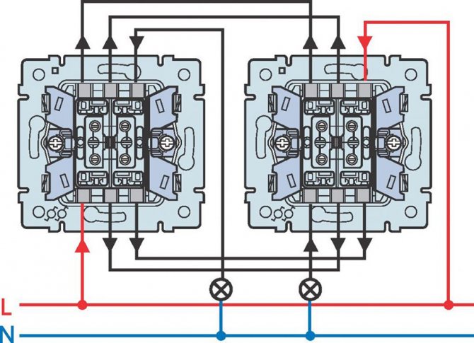
Unlike conventional switches, pass-through switches have not two, but three contacts and can switch the “phase” from the first contact to the second or third
Segment-leading manufacturers
Many companies produce such sensors. Among them there are recognized leaders. Among them is the German company Sick, as the main manufacturer of such high quality products. Autonics supplies the market with inductive and capacitive limit switches.
High quality non-contact sensors are produced by the Russian. They feature ultra-high tightness (IP 68). These limit switches work in the most dangerous environments, including explosive ones, various mounting methods are available.
Ukrainian limit switches are popular. Here they produce switches and limit switches VP, PP, VU.The warranty, subject to all operating rules, is 3 years.
Advantages of contactless models
The main advantage of proximity switches is energy savings. Electricity is not wasted in the absence of people in the room. A person does not need to take part to turn the light on or off. Therefore, the use of such models is considered comfortable.
Technical simplicity is a plus of standard contact switches, but there are some disadvantages:
- Small resource when applying the maximum load. If the contacts open, a spark is generated, causing the circuit breaker to break. In the presence of direct current, a capacitor that has a parallel connection to the contacts will help eliminate the accident. In the presence of alternating current, a refractory soldering of tungsten will be required.
- The downside of the contact device is considered to be a strong sensitivity to dust and dirt. This causes an electrical circuit to break. Further, there is a decrease in the interaction of contacts, and as a result - overheating and breakdown.
A huge selection makes it possible to find an element for use in a particular case. If you need to implement touch control, a capacitive switch is suitable, and for use in dirty conditions, it is better to choose an inductive option.


