- Main characteristics of the collector system
- The principle of operation of the collector system
- Positive qualities and disadvantages
- The expediency of installing a collector system
- 1 System installation
- Connection rules and installation features
- Option # 1 - without additional pumps and hydraulic arrows
- Option # 2 - with pumps on each branch and a hydraulic arrow
- Assembly of the factory manifold
- Most wanted models
- What is a heating manifold for?
- Collector heating device
- How to choose a place for installation?
- System calculation
- How to calculate the correct pipe diameter?
- Common house collector group
- Collector system device
- Beam scheme and underfloor heating
- Collector device and principle of operation
- How to make a polypropylene collector with your own hands
- Conclusions and useful video on the topic
Main characteristics of the collector system
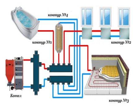
The main difference between the collector and the standard linear method of redistributing the heat carrier is the division of flows into several independent channels. Various modifications of collector installations can be used, differing in configuration and size range.
Often, the collector heating circuit is called radiant. This is due to the design features of the comb.When examining the device from the top point, you can see that the pipelines extending from it resemble the image of the sun's rays.
The design of the welded manifold is quite simple. To the comb, which is a pipe of round or square section, connect the required number of branch pipes, which, in turn, are connected to the individual lines of the heating circuit. The collector installation itself is interfaced with the main pipeline.
Shut-off valves are also installed, by means of which the volume and temperature of the heated liquid in each of the circuits is adjusted.
The manifold group, equipped with all the necessary parts, can be purchased ready-made or assembled independently, which will significantly reduce the cost estimate when designing heating
The positive aspects of operating a heating system based on a distribution manifold are as follows:
- The centralized distribution of the hydraulic circuit and temperature indicators occurs evenly. The simplest model of a two- or four-loop ring comb can balance the performance quite effectively.
- Regulation of operating modes of the heating main. The process is reproduced due to the presence of special mechanisms - flow meters, a mixing unit, shut-off and control valves and thermostats. However, their installation requires correct calculations.
- Serviceability. The need for preventive or repair measures does not require shutting down the entire heating network. Due to the sliding pipeline fittings mounted on each individual circuit, it is easy to block the flow of coolant in the required area.
However, there are also drawbacks to such a system. First of all, the consumption of pipes increases. Compensation for hydraulic losses is carried out by installing a circulation pump. It is required to be installed on all collector groups. In addition, this solution is relevant only in closed-type heating systems.
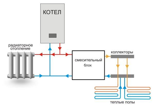
The principle of operation of the collector system
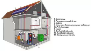
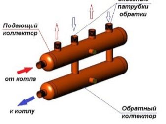
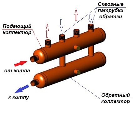
A collector is a metal comb with leads for connecting pipes and appliances. The collector heating system is two-pipe. Hot water is supplied through one comb, and pipes are connected to the other, collecting cooled water (return).
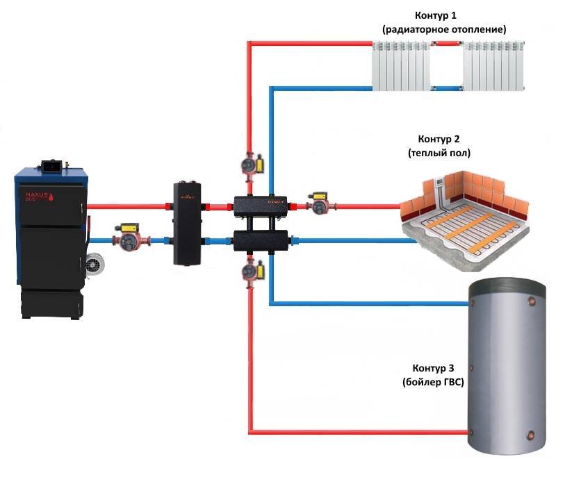
This heating system works as follows. Water from the heating source enters the supply manifold (supply distribution manifold), and from there it carries heat through pipes to each radiator and underfloor heating. The cooled water from the radiators through the return comb (return manifold) returns to the heating boiler.
The collector heating system has a closed expansion tank and a circulation pump that moves the coolant. The minimum volume of the expansion tank is equal to at least 10% of the total volume of all heaters. The pump is installed on any of the pipelines going to the collectors.
installed in special cabinets lower pipe connection to radiators the best opportunity to hide pipes in the Mayevsky half-faucet
Each hydraulic circuit located after the manifolds is an independent system. This made it possible to create underfloor heating. These are floors in which pipes are laid in parallel or in the form of spirals that heat the floor surface.The pipes are laid on a heat-insulating gasket, connected to a collector, and after checking the tightness of the pipelines, they are poured with concrete. The height of the screed should not exceed 7 cm. The laying step and the diameter of the pipes are determined by calculation. The length of one heating coil should not exceed 90 m. Basically, metal-plastic pipes are used for underfloor heating, which easily accept any curvature.
When underfloor heating is operating, the temperature decreases along the height of the room, and when radiators are installed, on the contrary, the higher, the warmer.
Positive qualities and disadvantages
The main differences between closed heat supply networks and outdated open systems with natural circulation are the lack of contact with the atmosphere and the use of transfer pumps. This gives rise to a number of advantages:
- the required pipe diameters are reduced by 2-3 times;
- the slopes of the highways are made minimal, since they serve to drain water for the purpose of flushing or repair;
- the coolant is not lost by evaporation from an open tank, respectively, you can safely fill pipelines and batteries with antifreeze;
- ZSO is more economical in terms of heating efficiency and cost of materials;
- closed heating lends itself better to regulation and automation, can act in conjunction with solar collectors;
- forced flow of the coolant allows you to organize floor heating with pipes embedded inside the screed or in the furrows of the walls.
The gravitational (gravity-flowing) open system outperforms the ZSO in terms of energy independence - the latter is unable to operate normally without a circulation pump.Moment two: a closed network contains much less water and in case of overheating, for example, a TT boiler, there is a high probability of boiling and the formation of a vapor lock.
The expediency of installing a collector system
But it is impossible to install a collector heating system in an apartment of old multi-storey buildings, because a tee heating system is already working there. For the operation of the collector system, it is necessary to close the hydraulic circuit, which is necessary to create the circulation of the coolant in the system. If a closed hydraulic circuit is created in one apartment, other apartments will be cut off from the heating system.
The collector heating system also cannot be used in areas with unstable power supply, since when the circulation pump stops, the water will freeze and the pipes will fail. But the situation can be somewhat corrected by the use of non-freezing liquid for the heating system.
1 System installation
The first task that the owner of a private house must solve is to determine the type of heating of the building. It is necessary to understand whether a collector system is needed at all and whether its use will become expedient. Such a scheme will be effective if the cooling rate of the coolant in the pipes is very high, as well as in large houses, since the classical heating system in them will always heat up the premises poorly.
The main functional advantage of such a circuit is the distribution of the entire circuit into many circuits. In rooms with a small quadrature, 2 independent circuits can also be installed, and for large buildings (two- and three-story) from two or more.Such a distribution helps to effectively heat an apartment or a country cottage, since the coolant does not have time to cool down much. In classical schemes, this is impossible to implement.
Before deciding on the installation of such a system in the house, it is necessary to take into account several decisive factors, in the presence of which it will be advisable to use it:
- Large area of the house. To heat the house completely, you need to make several circuits.
- When using conventional heating, you need to turn off some rooms to save energy.
- The tee scheme is inefficient. When used, the hydraulic distribution can be unevenly distributed throughout the system.
If, when measuring temperature indicators in the return pipe, the water is colder by 25 degrees or more from the initial figure when leaving the boiler, then this is the reason for installing a collector system.
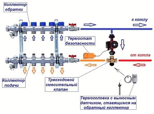
Connection rules and installation features
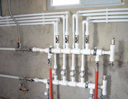
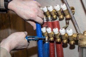
Installation of the comb begins with attaching it with brackets to the wall, where it will be located openly or in a closet. Then it will be necessary to attach the main pipes from the heat source to the ends and proceed to the piping.


Option # 1 - without additional pumps and hydraulic arrows
This simple option assumes that the comb will serve several circuits (for example, 4-5 radiator batteries), the temperature is assumed to be the same, its regulation is not provided. All circuits are connected directly to the comb, one pump is involved.
The characteristics of pumping equipment should be related to the performance of the heating system and the pressure created in it.So that you can choose the best pump that is ideal for its characteristics and cost, we recommend that you familiarize yourself with the rating of circulation pumps.
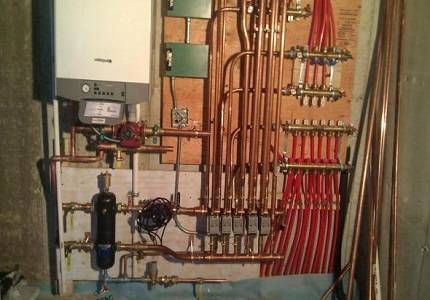
A master with experience in collector equipment knows how to correctly install a distribution manifold and hide it in a cabinet so as to hide all pipes
Since the resistance in the circuits is different (due to different lengths, etc.), it is necessary to ensure optimal consumption of the coolant by balancing.
To do this, not shut-off valves, but balancing valves are placed on the nozzles of the return manifold. They can regulate (although not exactly, but by eye) the coolant flow in each circuit.
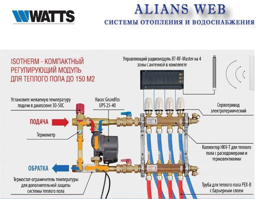
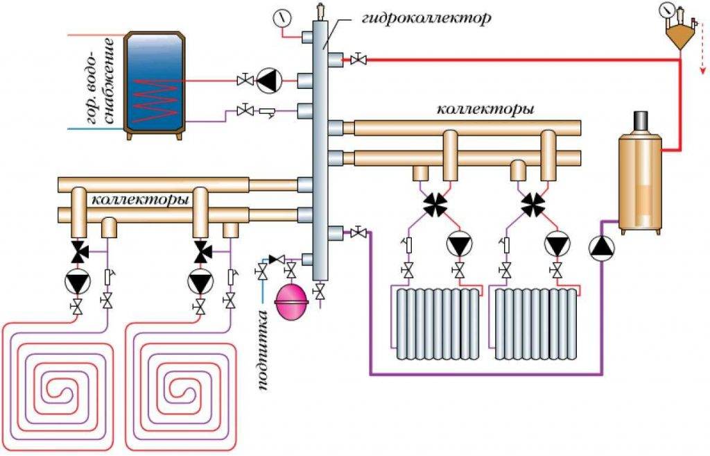
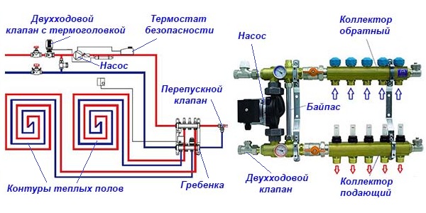
Option # 2 - with pumps on each branch and a hydraulic arrow
This is a more complex option, which, if necessary, will need to power consumption points with different temperature conditions.
So, for example, in radiator heating, water heating ranges from 40 to 70 ° C, a warm floor is enough in the range of 30-45 ° C, hot water for domestic needs must be heated to 85 ° C.
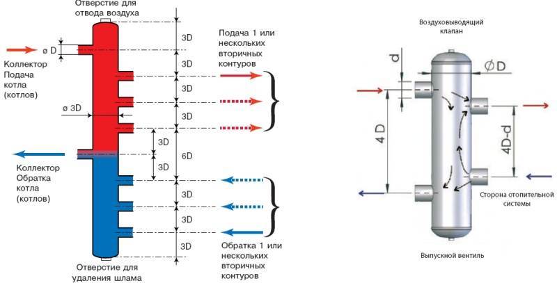
In the strapping, a hydraulic arrow will now play its special role - a piece of deaf from both ends of the pipe and two pairs of bends. The first pair is needed to connect the hydraulic arrow to the boiler, the distribution combs are joined to the second pair. It is a hydraulic barrier that creates a zone of zero resistance.
For boilers with a power of 50 kW and above, it is recommended to use a distribution manifold together with a hydraulic arrow without fail. It is mounted vertically on the wall with separate brackets to avoid excessive horizontal overload.
On the comb itself there are mixing units equipped with three-way valves - temperature control devices.Each outlet branch pipe has its own pump operating independently of the others, providing a specific circuit with the necessary amount of coolant.
The main thing is that these pumps do not exceed the total power of the main boiler pump.
Both considered options are used when installing distribution manifolds for boiler rooms. Everything you need is sold in specialized stores. There you can buy any unit assembled or element by element (based on savings due to self-assembly).
To further reduce future costs, you can make a heating distribution comb with your own hands.
The collector for the boiler room is located in close proximity to the heating equipment and is exposed to high temperatures that only metal can withstand.
Not so stringent requirements for thermal stability are imposed on a local distribution manifold; not only metal pipes, but also polypropylene, metal-plastic pipes are suitable for its manufacture.
For a local distribution manifold, it is easiest to select suitable scallops from those that are commercially available. In this case, one should take into account the material from which they are made - brass, steel, cast iron, plastic.
Cast scallops are more reliable, eliminating the possibility of leakage. There are no problems with connecting pipes to combs - even the most inexpensive models are threaded.
Distribution combs assembled from polypropylene parts impress with their cheapness. But in an emergency, the joints between the tees will not withstand overheating and will flow
Craftsmen can solder a collector made of polypropylene or metal-plastic, but you still have to buy threaded lugs, so the product will come out not much cheaper in terms of money than a finished one from a store.
Outwardly, it will be a set of tees interconnected by tubes. The weak point of such a collector is insufficient strength at high heating temperatures of the coolant.
The comb can be round, rectangular or square in cross section. Here, the transverse area comes first, and not the shape of the section, although from the position of hydraulic laws, a rounded one is preferable. If the house has several floors, it is better to install local distribution collectors on each of them.
Assembly of the factory manifold
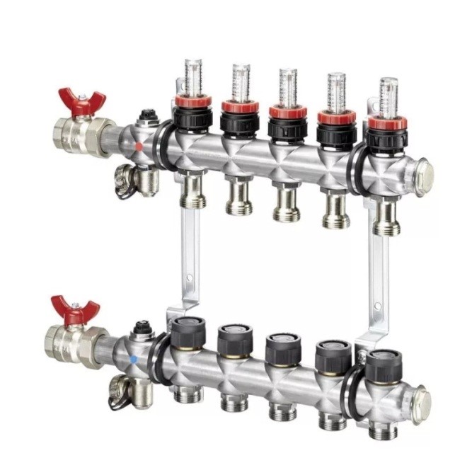
Let's start with a specific example of what a ready-made distribution unit from the manufacturer consists of.
Table 1. Assembly of the factory manifold.
| Steps, photo | Comment |
|---|---|
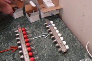 Step 1 - Unpacking the Assembly Parts Step 1 - Unpacking the Assembly Parts | This collector unit is called ready only because all the necessary and optimally selected elements have already been assembled. He himself is in a disassembled state, and all the details will still have to be put together. |
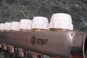
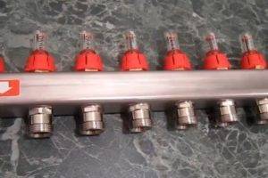 Step 2 - feed comb Step 2 - feed comb | This is a feed comb, each outlet of which is equipped with a flow meter (red device on top). Through it, the temperature range in the circuits is set. It is on this comb, if necessary, that the coolant supply to the circuits is shut off. |
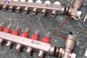
 Step 3 - reverse comb Step 3 - reverse comb | The return manifold, in contrast to the supply manifold, is equipped with push-operated thermostatic shut-off valves.From above they are covered with caps, on the front side of which the direction of rotation is indicated (plus and minus), by turning which you can adjust the feed manually. |
 Step 4 - Servo Step 4 - Servo | Instead of a cap, a servo drive can be installed on the valve, which will automatically regulate the flow of water. These devices are not included in the kit, but are purchased separately. |
 Step 5 - room thermostat Step 5 - room thermostat | The desired temperature is set on the thermostat, and it already sends a signal to the servo. |
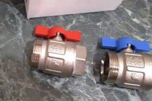 Step 6 - ball valves Step 6 - ball valves | By means of taps, the heating system is turned off. |
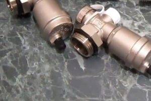 Step 7 - drain nodes Step 7 - drain nodes | At the end of each collector, nodes are installed through which water can be drained from the system or air can be bled. |
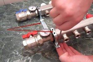
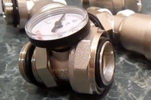 Step 8 - Thermometers Step 8 - Thermometers | The purpose of the thermometer, we think, does not need to be explained. |
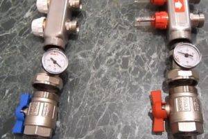 Step 9 - tying the comb on the side of the inlet and outlet of the coolant Step 9 - tying the comb on the side of the inlet and outlet of the coolant | On the left side of the supply comb there is a hole through which heated water flows from the boiler. A tee with a thermometer is first screwed onto it, and then a ball valve, through which it will be connected to the pipeline. The same is done on the return. |
 Step 10 - installation of drain units Step 10 - installation of drain units | On the right, drain nodes are screwed onto both combs. |
 Step 11 Mounting the Bracket Step 11 Mounting the Bracket | The collector assembly kit includes a bracket, through which both combs are connected together, and then hung on the wall. |
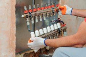 Step 12 - hanging the node on the wall Step 12 - hanging the node on the wall | The assembly assembly is attached to the wall, or installed in a special cabinet. |
 Step 13 - Connecting the Loops to the Manifold Step 13 - Connecting the Loops to the Manifold | It remains only to connect the supply pipeline and circuits to the collector. |
Most wanted models
1. Oventrop Multidis SF.


The inch comb of heating is intended for the organization of heating by a water heat-insulated floor. Manufactured from high wear resistant tool steel. Main characteristics:
- allowable pressure in the circuit - 6 bar;
- coolant temperature - +70 °С.
The series is produced with M30x1.5 valve inserts, and can also be equipped with a flow meter for connecting circuits located in different rooms. Bonus from the manufacturer - soundproof mounting clamps. The number of simultaneously serviced branches is from 2 to 12. The price, respectively, is 5650-18800 rubles.
To work with high-temperature appliances, Oventrop suggests using the distribution manifold of the Multidis SH stainless steel heating system with a Mayevsky tap. The design already withstands 10 bar at + 95-100 ° C, the throughput of the comb is 1-4 l / min. However, for products with 2 circuits, the indicators are slightly weaker. The cost of Oventrop SH hydrodistributors fluctuates in the range of 2780-9980 rubles.
Plumbers: You'll pay up to 50% LESS for water with this faucet attachment
- HKV - brass manifold for underfloor heating. Holds a pressure of 6 bar in the range of + 80-95 ° С. Rehau version D is additionally equipped with a rotameter and a tap for filling the system.
- HLV is a heating distribution manifold designed for radiators, although its characteristics are identical to those of HKV. The only difference is in the configuration: there is already a Eurocone and the possibility of a threaded connection with pipes.
Also, the manufacturer Rehau offers to buy separate Rautitan combs with three exits for pipeline installation using compression sleeves.
Distribution collector of heating from steel with an anticorrosive covering. It works in systems with temperatures up to +110 °C at a pressure of 6 bar and hides in a special heat-insulating casing. The capacity of the comb channels is 3 m3/h. Here, the choice of designs is not too rich: only 3 to 7 circuits can be connected. The cost of such hydraulic distributors will be from 15,340 to 252,650 rubles.
Stainless steel manifolds are produced in an even more modest assortment - for 2 or 3 circuits. With the same characteristics, they can be purchased for 19670-24940 rubles. The most functional Meibes line is the RW series, which already comes with various connecting elements, thermostats and manual valves.
- F - a flow meter is built into the supply;
- BV - has quarter taps;
- C - provides for building a comb through a nipple connection.
Each Danfoss heating manifold allows a pressure in the system of 10 atm at the optimum temperature (+90 °C). The design of the brackets is interesting - they fix the paired combs with a slight offset relative to each other for more convenient maintenance. At the same time, all valves are equipped with plastic heads with printed markings, which allows you to set their position manually without the use of tools. The price of Danfoss models, depending on the number of connected circuits and additional options, varies between 5170 - 31,390.
The heating manifold can be selected for a euro cone with 1/2″ or 3/4″ outlets or with a metric threaded connection.Far combs withstand pressure up to 10 atm at temperatures not exceeding +100 °C. But the number of outlet pipes is small: from 2 to 4, but the price is the lowest of all the products considered in our review (730-1700 rubles for an unpaired distributor).
Selection Tips
Despite the seeming simplicity of the combs, they need to be selected based on several technical parameters at once:
1. Head in the system - this value determines what material the distribution manifold can be made of.
2. The throughput must be sufficient so that the connected heating circuits do not “starve” from a lack of coolant.
3. Energy consumption of the mixing unit - as a rule, it is determined by the total power of the circulation pumps.
4
The ability to add contours - this parameter should be paid attention only when it is planned to build additional objects in the future that need heating
The number of nozzles on the hydraulic distributor must correspond to the number of connected branches (heaters). In some cases, it is better to install several collectors, for example, in a two-story house - one block at each level. It is also allowed to install unpaired combs at different points: one on the supply, the other on the return.
Finally, experts and experienced installers in their reviews advise not to save on buying a good collector. In order for it to serve for a long time and not cause any special problems, the name on the box must be known.
What is a heating manifold for?
In the heating system, the collector performs the following functions:
- receiving heat carrier from the boiler room;
- distribution of coolant over radiators;
- return of the coolant to the boiler;
- removal of air from the system.In the sense that an automatic air vent is installed on the collector, through which air is removed. However, the air vent is not always placed on the collector, it can also be on radiators;
- shutdown of a radiator or a group of radiators. However, you can turn off each radiator individually by simply shutting off the coolant using valves installed on the radiator itself:
That is, it is not necessary to have some backup valves on the collector.
A tap is also often placed on the manifold, through which the system can be filled or drained.
When installing a collector, we have many pipes of the same type coming from radiators, so these pipes need to be marked in some way so as not to connect, say, both the supply and return of one radiator to one collector, for example, a supply one - in this case, the coolant circulates will not.
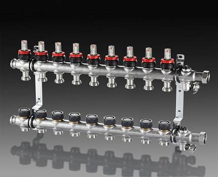
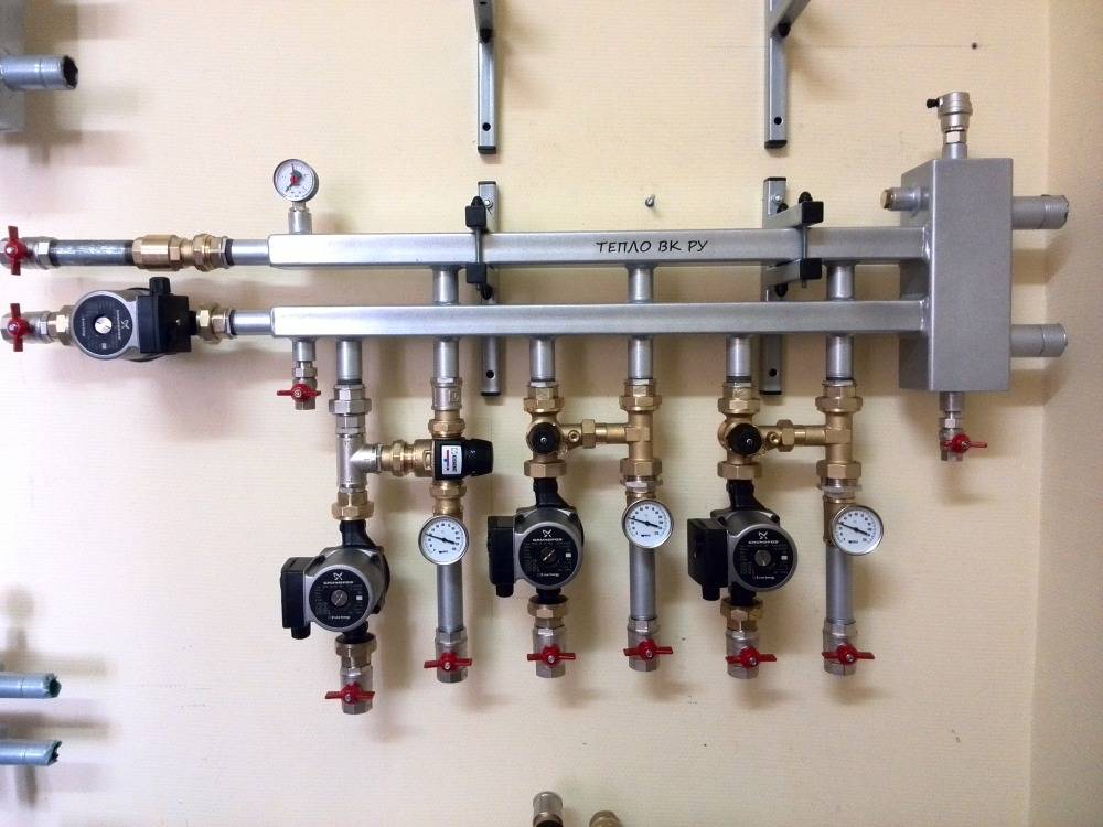
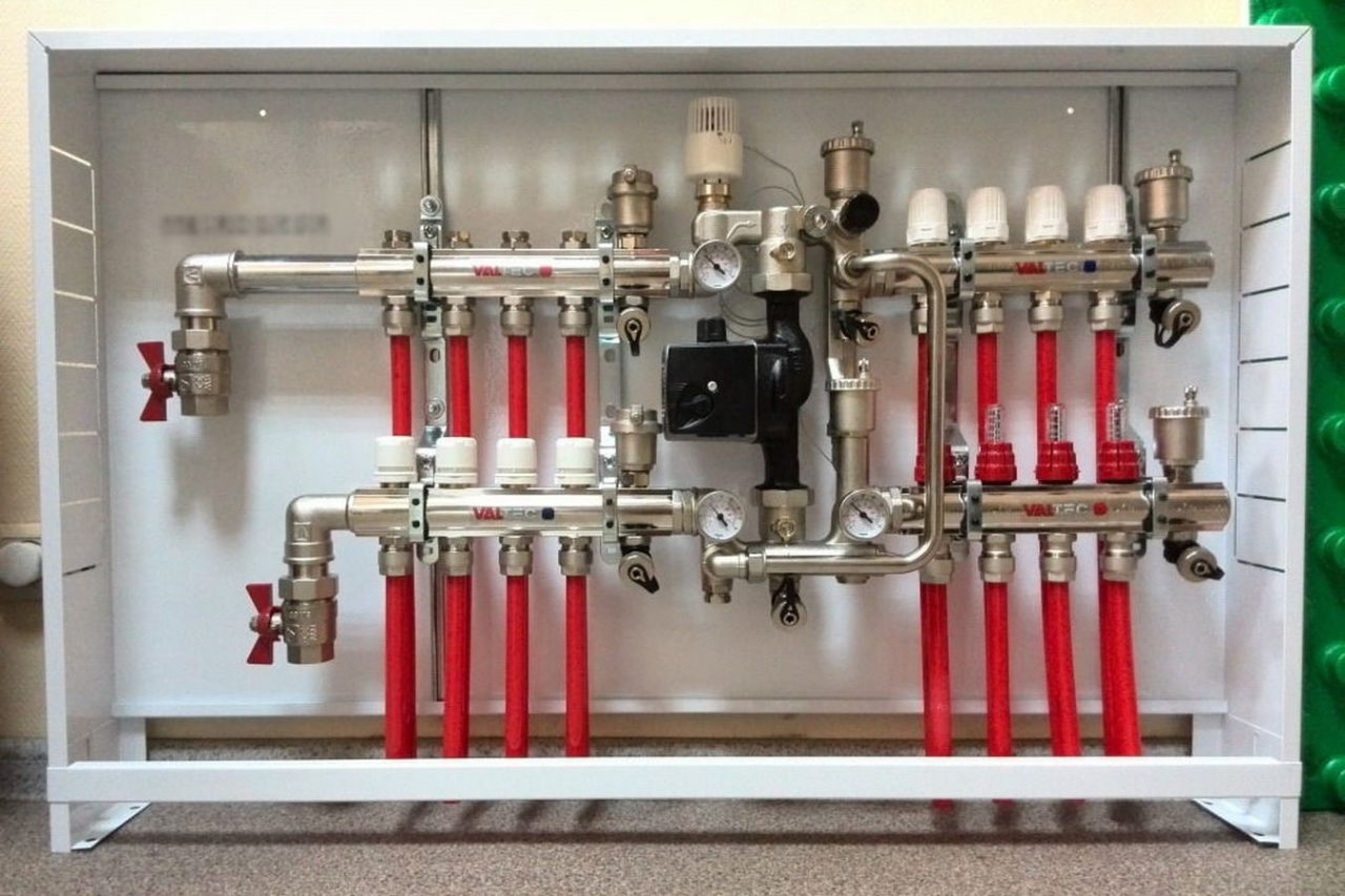
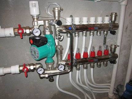
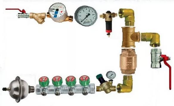
The figure below shows a purchased heating manifold, which is sold in specialized stores:
Such manifolds already have everything you need: valves for shutting off the coolant, automatic air vents with shut-off valves, taps for feeding and draining the system. As already mentioned, on the collector you can do without valves to turn off the radiators.


Collector heating device
Radiation heating scheme is widely used in construction. Here, separate pipelines are laid to each radiator. This allows you to control the air temperature in each heat exchanger.
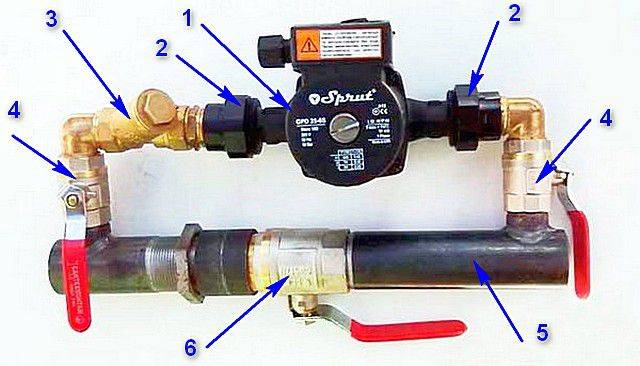
Photo 1. Collector for heating systems. The arrows show the component parts of the device.
It is in the beam system that a collector is used. It has the following characteristics:
- Provides automatic removal of air from the heating system.
- Disables a separate heatsink.
- Disables a group of heatsinks when needed.
- It distributes the heated coolant to radiators and underfloor heating pipes.
- Returns the cooled coolant to the pipes of the heating boiler.
The beam system also uses at least 2 combs, the totality of which is called the collector. One comb is responsible for the heated coolant, the second - for the cooled one.
Reference. Not only the collector can turn off the heating devices, but also individual taps that are located directly on the radiator.
A flow meter or thermostat and other elements are installed on the comb body.
How to choose a place for installation?
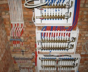
In multi-storey buildings, collector groups should be installed on all floors, this simplifies the check of the serviceability of the devices and the regulation of their operation.
Groups are mounted in special niches, which are located at a small height from the floor.
Combs and fittings are also placed in the niche.
In the absence of niches, the collector groups are placed in any premises with the necessary humidity. For such purposes, a corridor, a closet, a pantry are suitable.
The equipment is closed with special cabinets, overhead or built-in. Holes for pipes are made in their side walls.
System calculation
The formula for calculating collector heating is as follows:
S0 = S1 + S2 + S3 + Sn.
In this formula, S1 - Sn is the cross-sectional area of outgoing branches, where n is the number of branches. S0 is the sectional area of the comb.
Before applying the formulas, they are determined with the number of heating circuits, a drawing is made, and only then calculations are carried out.
After applying the formula, the final version of the scheme is compiled, which takes into account additional devices and indicates each individual group of pipelines.
How to calculate the correct pipe diameter?
To create an efficient heating collector, it is not enough just to build a circuit. It is also necessary to determine the correct diameter of the pipes.
When choosing pipes, consider:
- hydraulic losses. If pipes of different diameters are used in the system, this will inevitably lead to hydraulic losses.
- The speed of the coolant. The water must not cool down before it reaches the last radiator.
- Heat carrier volume. Pipes with a large diameter reduce fluid losses, but at the same time it increases the cost of heating the coolant.
It is also important to correctly carry out the calculations, this will help increase the efficiency of the entire heat supply system. The formula for the calculation is as follows:
The formula for the calculation is as follows:
m = PxV
When calculating the optimal pipe diameter, it is recommended to use special programs. They will make the result more accurate.


Common house collector group
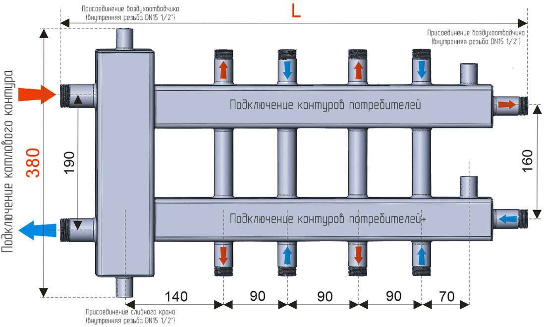
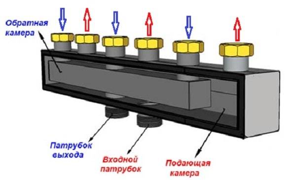
The main comb performs the same functions as the TP collector - it distributes the coolant along the branches of the heating network of various loads and lengths. The element is made of steel - stainless or black, the profile of the main chamber - round or square.
There are compact models of distributors for 3-5 circuits, made in the form of one pipe. What's the trick: the "return" collector is placed inside the supply chamber. As a result, we get 1 common building with 2 cameras of the same capacity.
In the vast majority of country houses up to 300 m², distribution collectors are not needed. For several heat consumers, it is used, described in a separate article. When should you think about buying a common house heating comb:
- the number of floors of the cottage - at least two, the total area - over 300 squares;
- for heating, at least 2 heat sources are involved - a gas, solid fuel, electric boiler, and so on;
- the number of individual branches of radiator heating - 3 or more;
- in the boiler room scheme there is an indirect heating boiler, heating circuits for auxiliary buildings, pool heating.
These factors must be considered separately and in combination, and in order to select a model of specific sizes, calculate the load on each branch. Hence the conclusion: it is better not to buy a collector without consulting an expert.
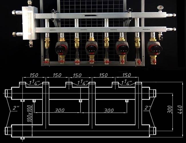
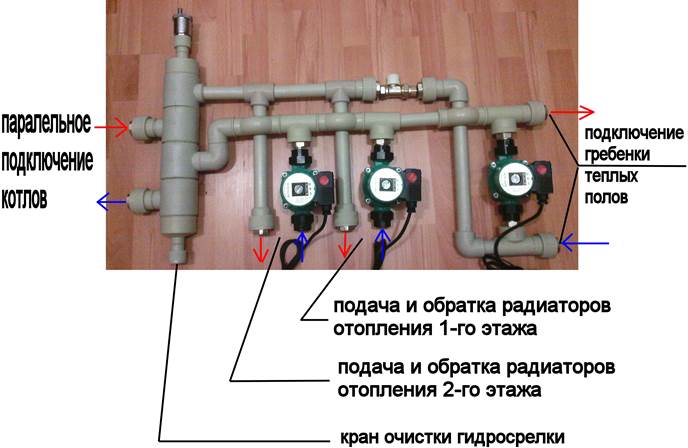
Drawing of a coplanar manifold and a photo of the finished product with pump groups
Collector system device
The basis of the collector heating scheme and the main working body is the distribution unit, commonly referred to as the system comb.
This is a special type of plumbing fittings, which is designed to distribute the coolant through independent rings and lines.
The collector group also includes: an expansion tank, a circulation pump and safety group devices.
The collector assembly for a two-pipe type heating system consists of two components:
- Input - it is connected to the heating unit through the supply pipe, takes over and distributes the coolant heated to the required temperature along the circuit.
- Output - it is connected to the return pipes of independent circuits, is responsible for collecting the cooled "return" water and redirecting it to the heating boiler.
The main difference between the collector wiring of heating and the traditional serial connection of devices is that each heater in the house has an independent supply.
Such a constructive solution makes it possible to control the temperature of each battery in the house, and, if necessary, completely turn it off.
Often, when designing heating, a mixed type of wiring is used, in which several circuits are connected to a node, each of which is controlled independently. But inside the circuit, the heaters are connected in series.
The comb is a section of a thick pipe, equipped with one inlet and several outlets, the number of which is determined by the number of connected circuits
Beam scheme and underfloor heating
The beam scheme allows you to combine a home-made collector for heating and a "warm floor" system. But this design has a number of features.
Before you start working on its creation, you need to familiarize yourself with them:
- installation of a heating manifold should be carried out on the condition that it is equipped with control valves and thermostatic valves on absolutely all circuits;
- when laying pipes for a “warm floor” heat supply system, electrothermal drives and thermostatic heads are certainly used. Thanks to these devices, "warm floors" will be able to quickly respond to changes in temperature and maintain the necessary microclimate in each of the rooms;
- the option for arranging the distribution system is different - typical (performed according to the standard scheme) and individual. The last method deserves special attention. In this case, the boiler operates in normal mode without significant temperature fluctuations, and fuel is consumed sparingly.
Collector device and principle of operation
The direct function of the collector in the water supply system is the distribution of one water flow into several flows of equal pressure.
On sale there are combs with two, three and four outputs. If more branches are needed, the distributors are interconnected. Thus, a water supply collector is assembled for the required number of outlets.
The collector is connected directly to the riser. On two opposite sides of the device, a threaded connection is provided (on the one hand, an internal thread, on the other, an external thread) for connecting to the line and connecting the combs to each other.
A plug or an additional plumbing fixture, for example, a membrane hydraulic shock absorber, is installed on the free end of the collector.
The diameter of the inlet hole is 20-40% larger than the outlet one. For example, on a standard manifold, for installing a water pipe in an apartment, the diameter of the inlet is 3/4 inch, the outlet is 1/2 inch.
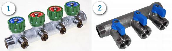
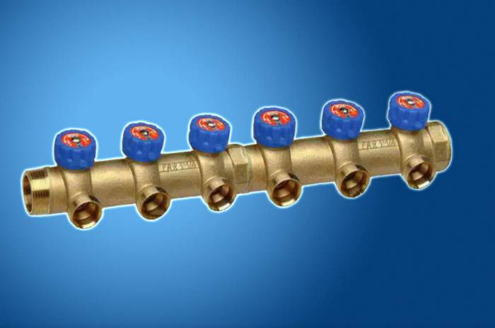
1. Collector with valves.2. Collector with ball valves.


At the outlets, both ball valves and valves can be installed, allowing not only to open and close the water flow, but also to regulate the flow rate in this area.
How to make a polypropylene collector with your own hands
Summer residents often want to save an extra penny and try to make a polypropylene collector with their own hands. If you have minimal skills in the field of plumbing, then making a collector yourself will not be difficult.
To design this device with your own hands, you need to buy all the necessary elements for its proper operation. To do this, you need to choose only high-quality elements. Do not buy cheap ones that can fail in two or three months. Moreover, the heating system is an important component of the life of your home.
Each collector has its own constituent elements:
- mixing valve;
- Pump (circular);
- Automatic air vent;
- Shut-off and balancing valves;
- Temperature sensor;
- Pressure gauge.
Also the need to have fittings, nipples and pipe adapters. To make the installation, it is necessary to connect all parts of the comb with a soldering iron designed for plastic pipes. Then connect the air vent and emergency drain cock. Another tap, together with an air vent, is placed on the second part of the manifold. Next, you should put the pump to the boiler.
After installation, two collectors must be connected to the heating circuit. The final part is the connection to the collector.
Thus, you will make a do-it-yourself polypropylene manifold. This will help your home use the heating system efficiently. Purchase all the necessary parts for the construction of the collector, follow the installation instructions and then you will make a quality collector. And the water distribution system will become much more efficient.
Conclusions and useful video on the topic
Installation of heating equipment with connection to a distribution manifold:
Making a comb with your own hands:
Compared to the traditional organization of the heating system, distribution combs increase its efficiency, and only the financial issue somewhat hinders the consumer's interest in this heating method. But if you have enough money, distribution combs are your ideal choice.
Have you implemented a collector heating system in your house? Or are you just planning its arrangement and something is not clear to you? Ask questions - we will try to answer them.
Or maybe you used a comb to connect the underfloor heating system? Share your personal experience of assembling and installing the system - leave yours in the block below.