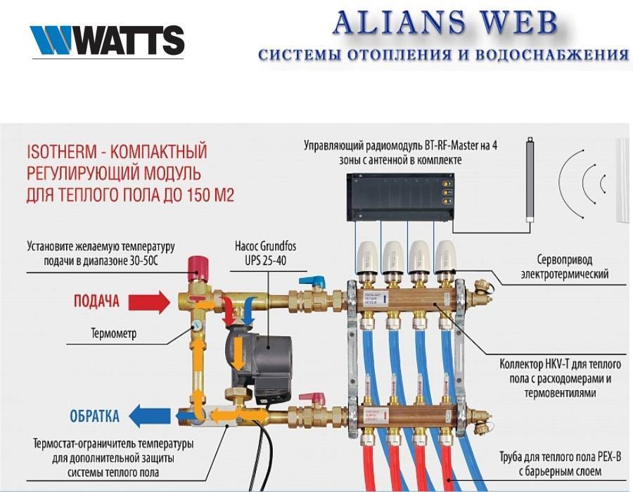
- What is a heating manifold for?
- Principle of operation
- Recommendations for choosing a heating collector
- Installation of a heating collector
- Types of heating systems and their difference
- The purpose of the collector for the heating system in the apartment: what does it serve?
- Principle of operation
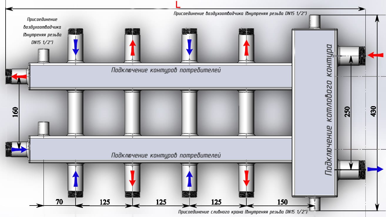
- Scheme
- Advantages
- Flaws
- The nuances of homemade work
- Coplanar heating distribution manifold
- Features of using a distribution manifold:
- Beam wiring connection diagram
- Preparatory work
- System installation
- General design principles
- Pipe selection
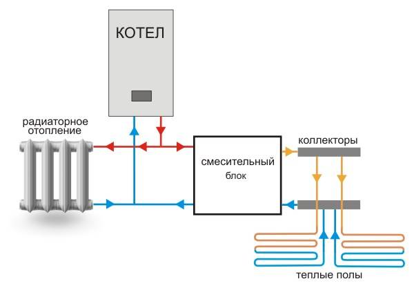
- The structure of the two-circuit system
- How it all works
- Safety valves for underfloor heating
- Collector classification
- Piping options
What is a heating manifold for?
In the heating system, the collector performs the following functions:
- receiving heat carrier from the boiler room;
- distribution of coolant over radiators;
- return of the coolant to the boiler;
- removal of air from the system. In the sense that an automatic air vent is installed on the collector, through which air is removed. However, the air vent is not always placed on the collector, it can also be on radiators;
- shutdown of a radiator or a group of radiators.However, you can turn off each radiator individually by simply shutting off the coolant using valves installed on the radiator itself:
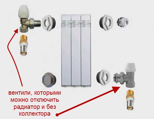
That is, it is not necessary to have some backup valves on the collector.
A tap is also often placed on the manifold, through which the system can be filled or drained.
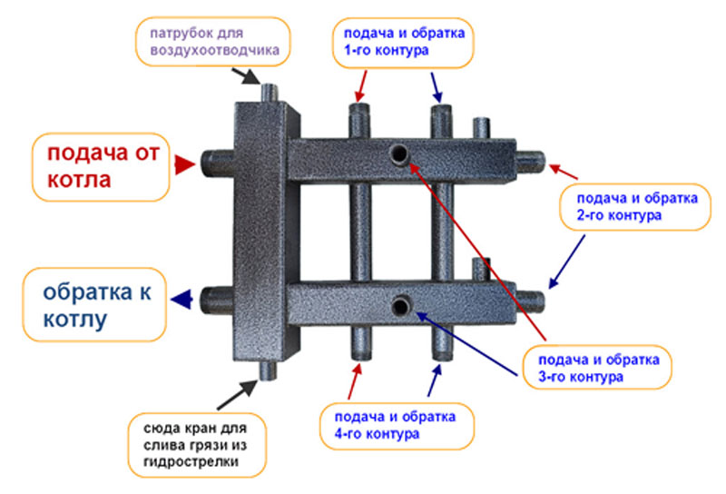
When installing a collector, we have many pipes of the same type coming from radiators, so these pipes need to be marked in some way so as not to connect, say, both the supply and return of one radiator to one collector, for example, a supply one - in this case, the coolant circulates will not.
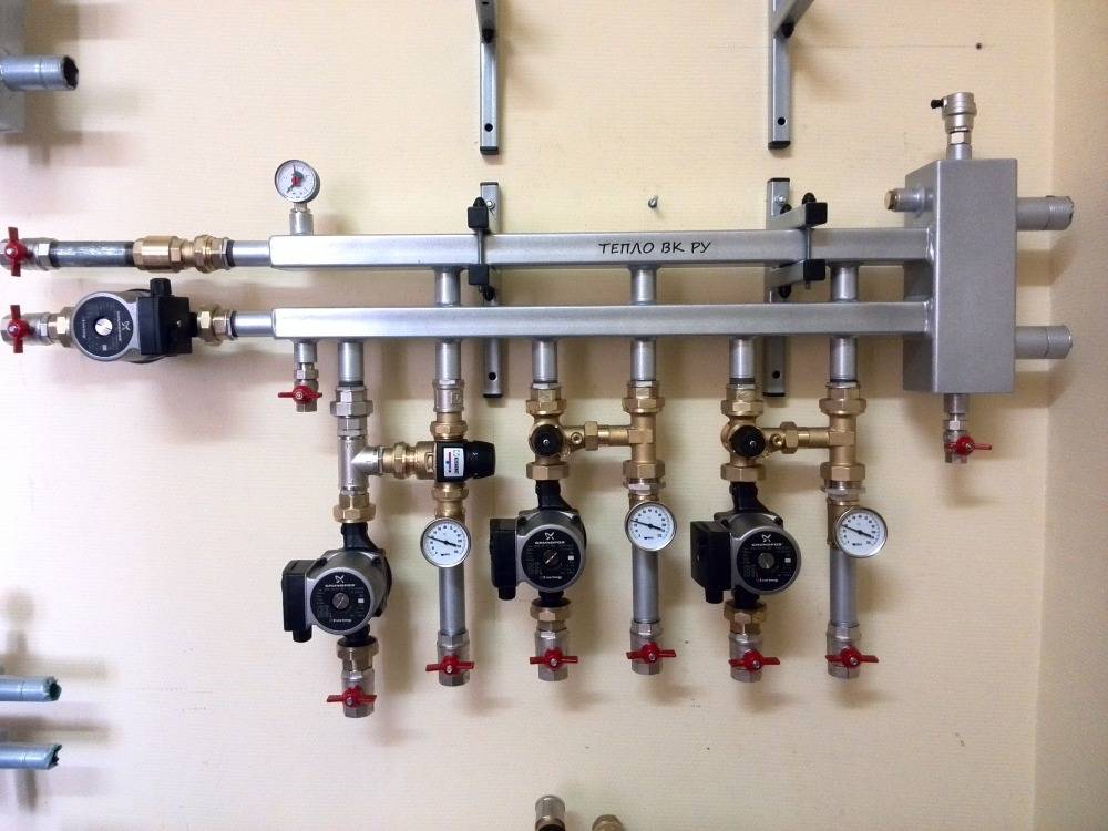
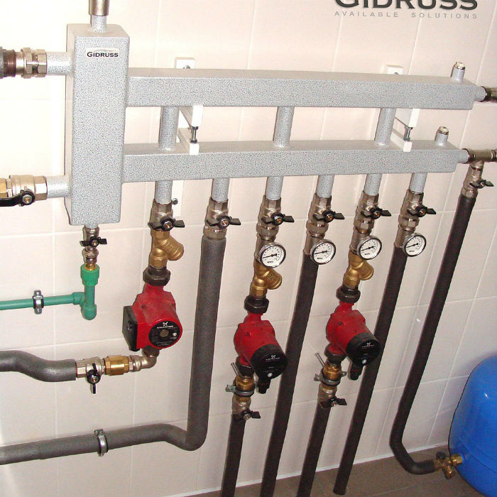
The figure below shows a purchased heating manifold, which is sold in specialized stores:
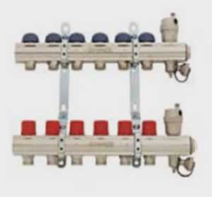
Such manifolds already have everything you need: valves for shutting off the coolant, automatic air vents with shut-off valves, taps for feeding and draining the system. As already mentioned, on the collector you can do without valves to turn off the radiators.
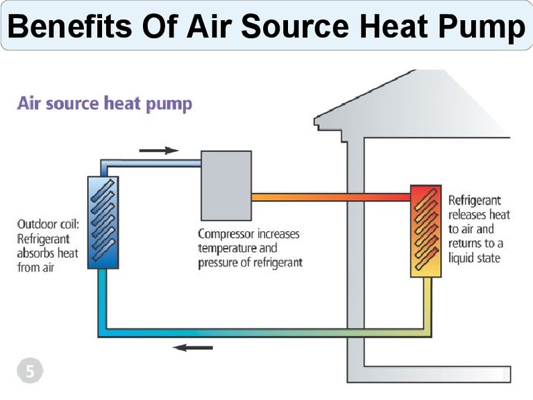
Principle of operation
The heating unit can be connected both to classic radiators and to “warm floors”. The difference will be only in the location of the collector, and not in the principle of operation. So, in any case, the collector system serves to distribute water flows to all heating devices, and this is achieved by a peculiar structure of the collector and connecting pipes to it in the future.
An important limitation is the need to be able to maintain the temperature. It should not change significantly when it enters the pipes. For example, for a "warm floor" system, a temperature of 40-50 degrees will be sufficient, and for radiators - 70-80 degrees. The collector must be designed for a temperature not lower than suitable.When connected to both a radiator and underfloor heating at the same time, it should be possible to dilute hot water with cold water or otherwise reduce the temperature below without affecting the overall flow.
Recommendations for choosing a heating collector
To choose a device, you need to pay attention to certain parameters:
- The indicator of the maximum allowable pressure. This determines the type of material from which the control valve is made.
- Node throughput and availability of auxiliary devices.
- The number of outlet pipes. They should be no less than the cooling circuits.
- Possibility of adding additional elements.
Operational characteristics are indicated in the device passport. For heating to work independently on each floor, a heating comb is needed, which means that the elements are connected one at a time per floor, and the type is selected according to the number of outlets (there must be as many or more than autonomous circuits).
Installation of a heating collector
Installation of the heating manifold it is better to foresee at the stage of forming an autonomous scheme. The installation is carried out in rooms without excessive humidity, it is possible to mount the collectors on the walls in special cabinets or without them, hanging the devices so that the distance from the floor is negligible.
There is no standard installation scheme, but there are a number of rules and features that should be considered:
- You need to install an expansion tank. The capacity of the structural element must be at least 10% of the total volume of the coolant in the system.
- Circulation pumps are installed for each circuit.
- The expansion tank is installed in front of the circulation pump on the coolant return flow pipeline.If a hydraulic arrow is used, then the tank is installed in front of the main pump - this will help ensure the desired intensity of coolant circulation in the small circuit.
- The location of the circulation pump does not really matter, but experts advise installing the device on the return line in a strictly horizontal position of the shaft, otherwise the air will cause the unit to remain without cooling and lubrication.
The high cost of equipment forces users to abandon the use of a collector circuit in the trunk. But there are options for self-manufacturing equipment.
Consider how to make a collector for heating with your own hands, and also prepare the necessary materials:
- polypropylene pipes with an index of 20 for an autonomous system and with an index of 25 for a central one - it is better to take reinforced pipes;
- plugs on one side in each group;
- tees, couplings;
- Ball Valves.
The assembly of the structure is simple - first connect the tees, then install a plug on one side, and a corner on the other (required for lower coolant supply). Now weld the segments onto the bends, on which the valves and other devices are installed. Soldering of polypropylene pipes is carried out with a professional device or a home soldering iron, before soldering, the ends are degreased, chamfered, after joining, the products must be allowed to cool.


The longest in the system is the accelerating collector, through which water rises when heated and then enters separate circuits. After the manufacture of the equipment, the connection is carried out in the usual manner - with the installation of a circulation pump for each circuit and the installation of an expansion tank.
With the ability to handle tools, the master can make a heating collector with his own hands, and will help in this video:
In this case, the device will cost much cheaper than factory analogues and is suitable for circuits of various types.
Types of heating systems and their difference
Heating systems are based on the principle of hot water circulation. Based on this, they distinguish:
- heating system with circulation based on natural pressure;
- heating system with circulation by means of a pump;
It is not worth dwelling on the description of the first system, since this installation has long been considered obsolete and is practically not used in the construction of new housing due to its low efficiency. Such heating is used in small private houses and some municipal institutions. We will only point out that its functioning is based on the principle of the physical difference in the density of warm and cold water, which leads to its circulation.
The forced circulation heating system provides for the presence of special pumps that provide circulation. This method makes it possible to heat more rooms than the first one. Accordingly, this system is considered the most effective. There is a huge selection of pumps for the circulation of coolant in the system, which makes it possible to vary with their power and other quality characteristics based on the size of the premises and their number.
The heating system with circulation by means of a pump is divided into:
- two-pipe (connecting radiators and pipes in a parallel way, which affects the speed and uniformity of heating);
- single-pipe (serial connection of radiators, which determines the simplicity and cheapness in laying the heating system).
The collector heating system is highly energy efficient compared to the above due to the fact that each radiator is connected personally to one supply and one return pipeline, the water supply through which is carried out using collectors.
Features of the collector system and its differences are as follows:
The collector wiring of the heating system provides that each radiator is regulated independently and does not depend on the work of others. In addition, other heating devices are often used in the collector system, which also work autonomously from the collectors. Radiators are mounted in parallel to the collectors, which, according to the principle of operation, makes the collector system similar to a two-pipe system.
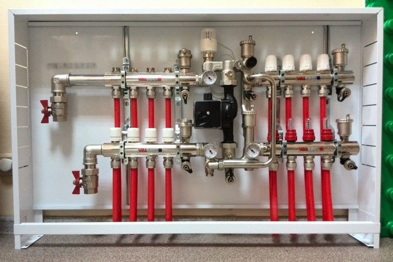
Installation of collectors is carried out in a separate utility room, or in a specially designated cabinet-stand, hidden in the wall. The place for the collectors must be planned in advance, as they can be quite impressive in size. The dimensions of the distribution manifolds depend on the power of the radiators, which depend on the size of the rooms.
The collector wiring of the heating system significantly outperforms the other heating systems listed above by the ability to dismantle and replace the radiator without having to stop the entire system. Also, collector wiring requires more pipeline for its operation than a two-pipe system.Despite the significant one-time costs during the construction phase, these measures have a positive effect on the further energy efficiency of the system. That is why the collector heating system has the greatest effect and quickly pays for itself in the construction of housing with a large area.
The purpose of the collector for the heating system in the apartment: what does it serve?
The collector is a hollow comb that is connected to the heating system. The device serves to regulate the supply of liquids to radiators, floor heating systems or convectors.
In addition, each device connected to the collector system has a supply and output pipe.
Therefore, it is called a comb, since one part is designed to supply heat to the device, and the second is to return and then reheat the liquid.
Principle of operation
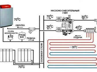
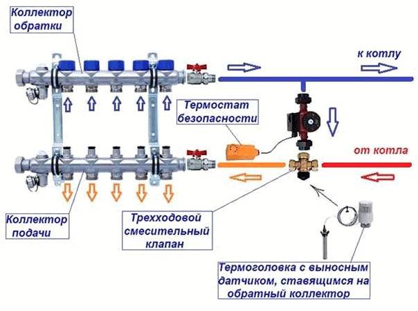
The mixing block is designed to supply water to heated convectors at the required temperature - mixing in supplies, if necessary, hotter water from the boiler.
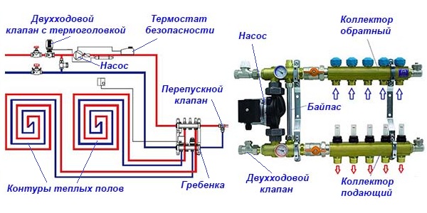
Photo 1. Circulation scheme: water leaves the mixer (3), passes through the pump (4) installed instead of the extension element.


The water returning from the loops enters the opposite side of the collector and through the connection (11) enters the mixing unit again. Here the high temperature supply water is mixed with the return water to ensure that the temperature of the supply to the loops is maintained at the required level.
The heated water is supplied from the boiler through the ball valve (1) and the outlet connection (2). When entering the mixer unit, an equal amount of water of a lower temperature is obtained, and the return water is discharged to the boiler through connection (11) and connection (2).
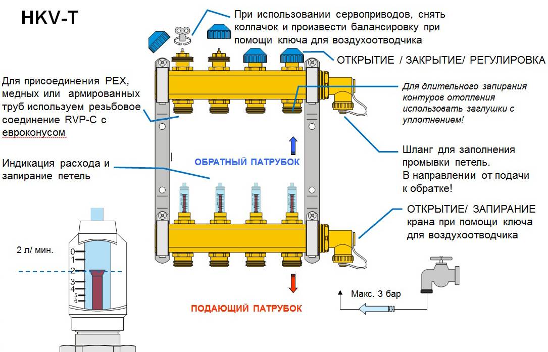
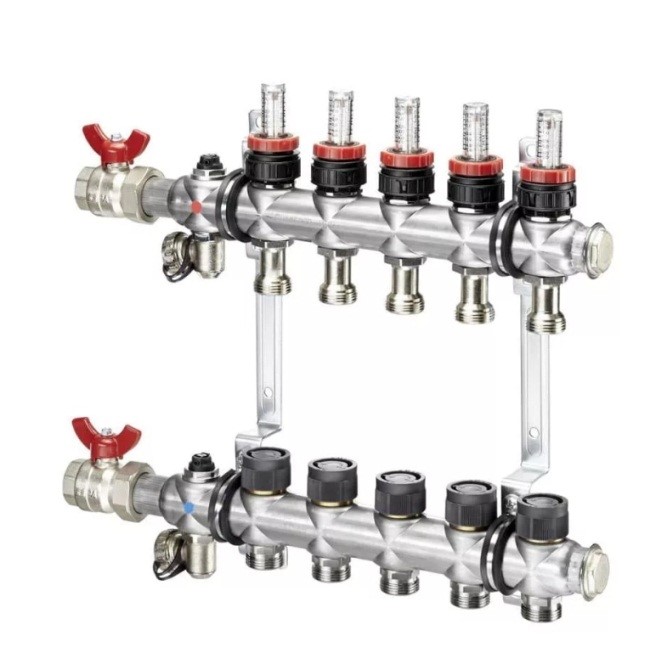
Scheme
- Two-centimeter pipe with a temperature sensor for connecting supply pipelines;
- Connection complete with adjustable bypass to return water to the boiler and back to the heating elements;
- Thermostatic mixer for controlling the temperature of the water circulating in the system. Adjustable in the temperature range from 18 °C to 55 °C;
- Template for installing a circulator with an outlet distance between connections of 130 mm;
- Safety thermostat with adjustable temperature probe from 10 to 90 °C (recommended 60 °C). The supply temperature is limited by closing the circulator when the set temperature is reached;
- Intermediate connection complete with automatic vent valve, bimetal temperature gauge with scale from 0 to 80 °C for temperature reading of the mixed water flow in the loops and drain cock.
- Pre-assembled chrome plated flanged brass manifolds with flow meter for installation with interchangeable nozzles for copper, plastic and multilayer pipe or with gas connection. These are distribution manifolds for supplying water to the panels;
- Manual air release valve;
- Chrome-plated flanged brass manifolds with integral valves. These are water collectors;
- Intermediate connection complete with automatic ventilation valve, bimetal temperature with a scale of 0 to 80 °C to read the temperature of the water returning from the heating elements and the drain cock;
- Return connection with built-in non-return valve for distribution in the mixer and return line to the boiler;
- Elbow with manual ventilation valve;
- Connection of the return pipeline to the boiler;
- Thermoelectric collectors for delivery to a high-temperature working system (radiators);
- Thermoelectric collectors for return from the high temperature operating system (radiators).
Advantages
- Constant uniform heat supply. With the help of a collector, equal pressure is achieved in all heating elements and the temperature will be the same throughout the house;
- The ability to adjust the heat - the heating system becomes very flexible. For example, if heating is temporarily not required in a separate room, then it is turned off.
In addition to the radiator, it is also possible to turn off the pipeline, which will reduce heat loss to 0;
The system has a high maintainability. Each element is replaced.
Flaws
The main disadvantage is the initial installation costs, which include the purchase of materials. Because of this, the installation of a collector for heating will not always be relevant. Sometimes it is better to stay on a standard two-pipe system.
The nuances of homemade work
The main condition for the correct operation of heating is the creation of a hydraulic balance in the system. The ring collector for heating must have the same capacity of the inlet pipe (section of the main pipe connected to the supply line) as the sum of the same indicators in all circuits. For example, for a system with 4 circuits, it looks like this:
D = D1 + D2 + D3 + D4
When making a heating manifold with your own hands, remember that the distance between the supply and return sections of the pipe must be at least six comb diameters.
When installing the device, the following nuances are taken into account:
- an electric boiler or a gas boiler is connected to the upper or lower nozzles
- the circulation pump cuts only from the end side of the comb
- heating circuits lead to the upper or lower part of the collector.
For heating a house with a large area, circulation pumps are installed on each circuit. In addition, to select the optimal volume of the coolant, additional equipment is installed on each inlet and outlet pipe - balancing flow meters and valves for adjustment. These devices limit the flow of hot liquid to a single nozzle.
In order for the boiler wiring collector to perform its functions in full, it is necessary that the length of all circuits connected to it be approximately the same length.
It is possible to additionally (but not necessarily) equip a mixing unit in the manufacture of heating collectors. It consists of pipes that connect the inlet and return combs. In this case, to regulate the amount of cold and hot water as a percentage, a two or three-way valve is mounted. It is controlled by a closed-type servo drive, which receives a signal from a temperature sensor installed in the heating circuit.
All this design allows you to adjust the heating temperature of a room or a separate circuit. If too hot water enters the collector in the boiler room, then the flow of cold liquid into the system increases.
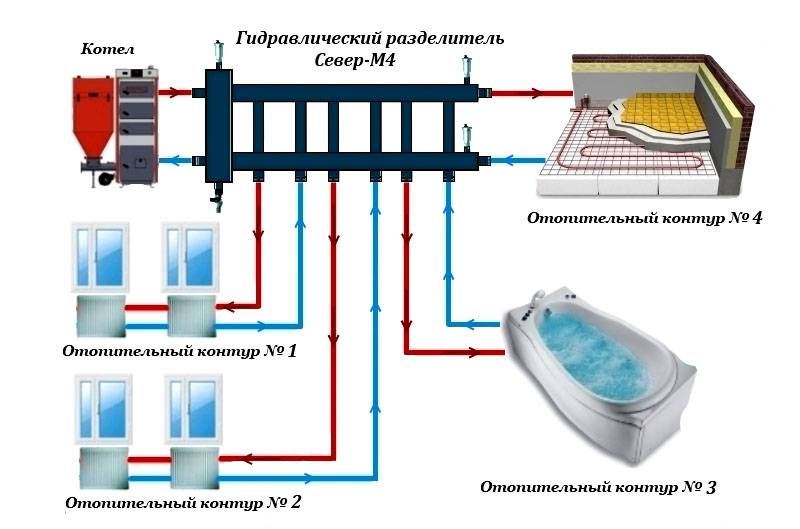
For a complex heating system in which several collectors are installed, a hydraulic arrow is installed. It improves the performance of the distribution combs.
The collector for the boiler room, which you make yourself, will ensure the normal functioning of the heating only if the parameters of the system stroke are accurately selected.Therefore, you first need to entrust the calculations to a professional, and then get to work.
Remember that the comfortable temperature in the house depends on many factors. Only a fully balanced system will ensure correct heating operation.
Coplanar heating distribution manifold
The main function of the distribution manifold is to control the uniform flow of coolant into the heating circuits.
The heating connection in this case occurs in parallel, and not in series, as is done in one- or two-pipe systems.
Features of using a distribution manifold:
- The water temperature when using the device is the same everywhere;
- The heating of each radiator (or a separate group of them) can be set to the maximum, without fear that this will somehow affect other circuits;
- The temperature in each room can be set separately and maintained stably.
In houses with several floors, a distribution manifold will allow you to maintain the temperature only where it is needed.
For example, if you do not need to heat the second floor, you can easily turn it off without affecting the other levels. You can also simply turn off one selected room or battery. This is the main convenience.
Beam wiring connection diagram
Pipelines, as a rule, are placed in a cement screed made on a subfloor. One end is connected to the corresponding collector, the other leads out of the floor under the corresponding radiator. A finishing floor is laid on top of the screed.When installing a radiant heating heating system in an apartment building, a vertical line is made in the channel. Each floor has its own pair of collectors. In some cases, if there is enough pump pressure and there are few consumers on the top floor, they are connected directly to first floor collectors.
Diagram of a radiant heating system
To effectively deal with traffic jams, air valves are placed on the manifold and at the end of each beam.
Preparatory work
During preparation for installation, the following work is performed:
- establish the location of radiators and other heat consumers (warm floors, heated towel rails, etc.);
- perform a thermal calculation of each room, taking into account its area, ceiling height, number and area of windows and doors;
- choose a model of radiators, taking into account the results of thermal calculations, the type of coolant, pressure in the system, calculate the height and number of sections;
- make the routing of direct and return pipelines from the collector to the radiators, taking into account the location of doorways, building structures and other elements.
There are two types of trace:
- rectangular-perpendicular, pipes are laid parallel to the walls;
- free, pipes are laid along the shortest route between the door and the radiator.
The first type has a beautiful, aesthetic appearance, but requires significantly more pipe consumption. All this beauty will be covered with a finishing floor and floor covering. Therefore, owners often choose free tracing.


It is convenient to use free computer programs for tracing pipes, they will help you complete the tracing, allow you to accurately determine the length of the pipes and draw up a statement for the purchase of fittings.
System installation
Laying the beam system on the subfloor will require a number of measures aimed at reducing transport heat losses and preventing freezing if water was chosen as the heat carrier.
Between the draft and finishing floor, a distance sufficient for thermal insulation should be provided.
If the subfloor is a concrete floor (or foundation slab), then a layer of heat-insulating material will need to be laid on it.
For ray tracing, metal-plastic or polyethylene pipes are used, which have sufficient flexibility. For radiators with a thermal power of up to 1500 watts, 16 mm pipes are used, for more powerful ones, the diameter is increased to 20 mm.
They are laid in corrugated sleeves, which provide additional thermal insulation and the necessary space for thermal deformations. After a meter and a half, the sleeve is fastened with screeds or clamps to the subfloor to prevent its displacement during the cement screed.
Next, a layer of heat-insulating material with a thickness of at least 5 cm is mounted, made of dense basalt wool, polystyrene foam or expanded polystyrene. This layer must also be fixed to the subfloor with dish-shaped dowels. Now you can pour the screed. If the wiring is carried out on the second floor or higher, it is not necessary to lay thermal insulation.
It is important to remember that no joints should remain under the flooded floor. If there are few consumers on the second, attic floor, and the pressure created by the circulation pump is sufficient, then a scheme with one pair of collectors is often used
Pipes to consumers on the second floor extend pipes from the collectors from the first floor.The pipes are assembled into a bundle and carried along a vertical channel to the second floor, where they are bent at a right angle and lead to the consumer accommodation points.
If there are few consumers on the second, attic floor, and the pressure created by the circulation pump is sufficient, then a scheme with one pair of collectors is often used. Pipes to consumers on the second floor extend pipes from the collectors from the first floor. The pipes are assembled into a bundle and carried along a vertical channel to the second floor, where they are bent at a right angle and lead to the points where consumers are located.
It is important to remember that when bending, the minimum bending radius for a given tube diameter must be observed. It can be viewed on the manufacturer's website, and for bending it is better to use a manual pipe bender
Sufficient space must be provided at the outlet of the vertical channel to accommodate the rounded section.
General design principles
There is no single instruction for drawing up a working draft of collector heating systems. In each case, heating devices and equipment are selected individually. But it will be useful for every interested person to get acquainted with a few tips of a general nature.
The collector scheme is not for a city apartment.
An exception can be considered cases when builders in new houses additionally install one pair of valves in apartments, to which a heating circuit of an arbitrary configuration can be connected. In this case, the collector wiring is boldly installed. With common risers for all apartments, a collector system is not possible.
Suppose there are several risers in the apartment and one or two heating devices are connected to each.You want a common collector circuit to be mounted, and install a pair of combs with heat distribution throughout the apartment on one riser, disconnecting from all other risers. As a result, you will get a large pressure drop and return temperature on your tie-in. This will lead to the fact that the batteries in the apartments of the neighbors in the riser will be almost cold. As a result, the visit of a representative of the housing office is inevitable, who will draw up an act on an illegal change in the heating configuration and oblige to make an expensive alteration of the heating system.
The system must be mounted so that the automatic air vent is located directly on the collectors. This is the best option, because sooner or later all the air will pass through them in the circuit.
The collector wiring system has many features, but some of them are also characteristic of other types of heating systems:
- The circuit must be equipped with an expansion tank, the volume of which must exceed 10% of the total volume of the coolant.
- The expansion tank is best placed in front of the circulation pump, on the "return", in the direction of water movement. When using a hydraulic arrow, the circuit must be designed so that the tank is installed in front of the main pump, which circulates water in a small circuit.
- The choice of the installation location of the circulation pumps in each circuit is not fundamental, but it is better to install them on the return flow. Here the operating temperature is lower. It is necessary to mount the pump so that the shaft is positioned strictly horizontally. Otherwise, at the first air bubble, the device will remain without lubrication and cooling.
Pipe selection
To determine which pipes the collector heating system is mounted on, it is necessary to understand the specifics of the collector wiring. Let's remember what can affect our choice:
- Pipes must be selected from those sold in coils. This allows you not to make connections in the wiring installed inside the screed.
- Pipes should not be afraid of corrosion, have a long service life. The reason is the same: to open the concrete floor due to the replacement of pipes is not included in our plans.
- The tensile strength and heat resistance of the pipes is selected depending on the operating parameters of the heating. For radiators in a private house, the optimal parameters are 50 - 75 ° C water temperature and a pressure of 1.5 atm., For warm floors at the same pressure, 30 - 40 ° C is enough.


When a collector heating system is installed in apartment buildings, which is quite rare, the operating pressure should be 10 - 15 atm. at the admissible temperature of the water carrier - 110 - 120 ° С. Based on these parameters, you have to make a choice of pipes.
Mounting the collector wiring is necessary when building a house. After laying the finishing floor, the installation of this system will not be economically feasible, since the floors will have to be opened. Most often, in this case, open wiring of heating systems is used.
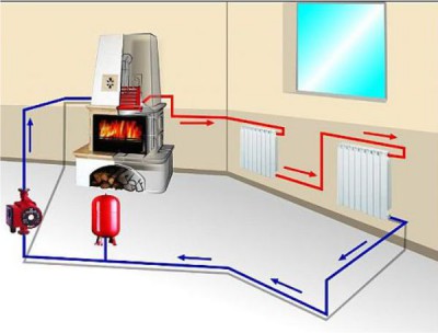
The structure of the two-circuit system
Heated floors can be electric, but they are more often made in already used houses, when the core mat or infrared film needs to be laid under the finish coat. If the house is just being built, then preference is usually given to the water system, and it is mounted directly into the draft concrete floor.There may be other options, but this one is the best.
If the house is just being built, then preference is given to a water-heated floor
The choice of underfloor heating
The main elements of such a heating scheme:
- water supply pipeline (main or autonomous);
- hot water boiler;
- wall heating radiators;
- piping system for underfloor heating.
Floor heating equipment
The boiler is able to heat water to boiling water, and this, as you know, is 95 degrees Celsius. Batteries can withstand this temperature without problems, but for a warm floor this is unacceptable - even considering that the concrete will take some of the heat. It would be impossible to walk on such a floor, and no decorative coating, with the exception of ceramics, can withstand such heating.
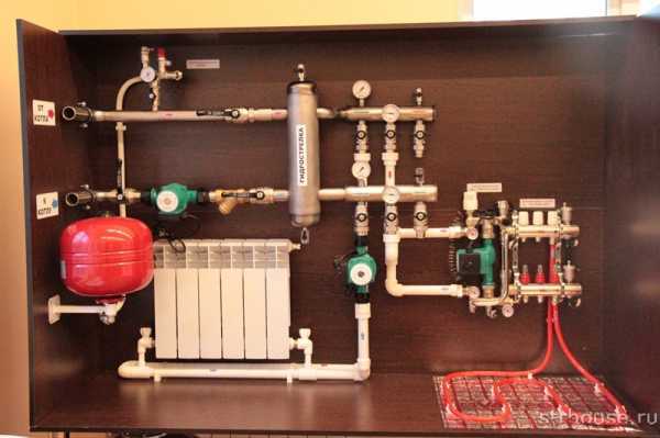
What if the water has to be taken from the general heating system, but it is too hot? This problem is solved by the mixing unit. It is in it that the temperature drops to the desired value, and the operation of both heating circuits in comfort mode will become possible. Its essence is impossibly simple: the mixer simultaneously takes hot water from the boiler and cooled water from the return, and brings it to the specified temperature values.
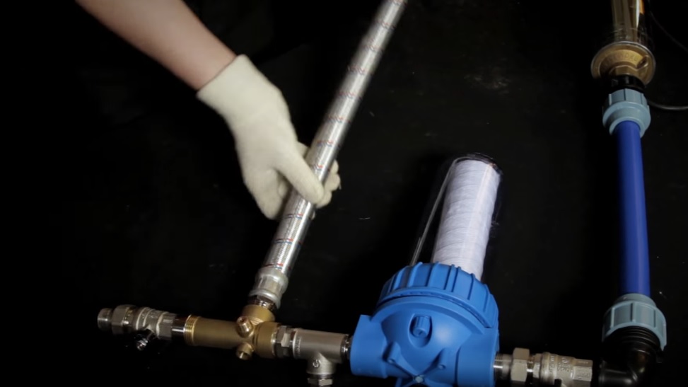
Pump and mixing unit for underfloor heating, assy
Underfloor heating from central heating
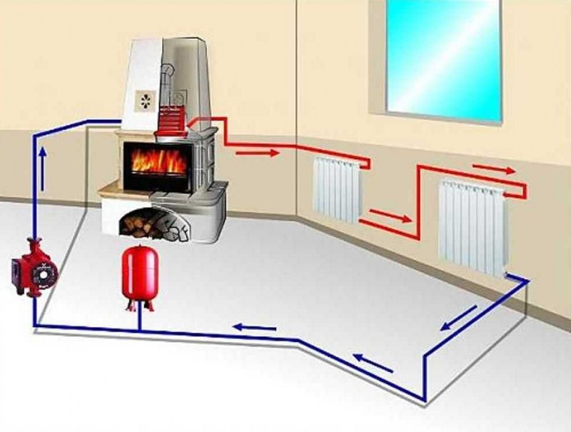
How it all works
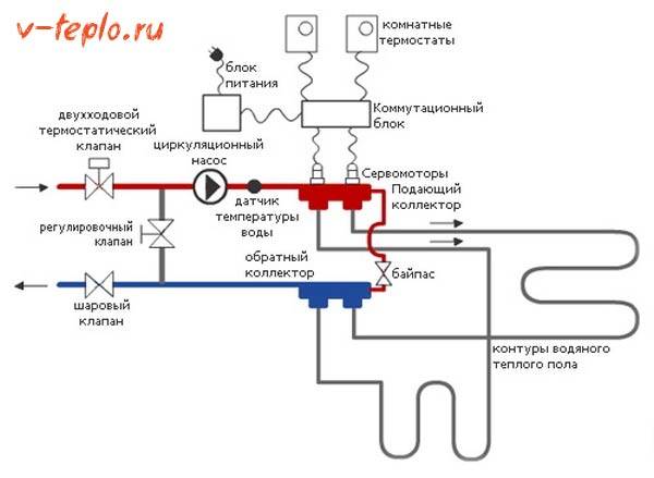
If we imagine the operation of a double-circuit heating system briefly, then it will look something like this.
-
The hot coolant moves from the boiler to the collector, which is our mixing unit.
- Here, the water passes through a safety valve with a pressure gauge and a temperature sensor, which you can see in the photo below. They regulate the pressure and temperature of the water in the system.
-
If it is too hot, the system is triggered to supply cold water, and as soon as the required coolant temperature is reached, the damper automatically closes.
- In addition, the collector ensures the movement of water along the circuits, for which a circulation pump is present in the structure of the assembly. Depending on the design of the system, it can be equipped with additional elements: bypass, valves, air vent.
What affects the energy consumption of a warm floor
Safety valves for underfloor heating
Manifold mixers can be assembled from separate parts, but it is easiest to purchase a complete assembly. Variations can be very different, but the main thing that distinguishes them is the type of safety valve used. Most often, options with two or three inputs are used.
Table. Main types of valves
| Valve type | Distinctive features |
|---|---|
| two-way | This valve has two inputs. On top is a head with a temperature sensor, according to the readings of which the water supply to the system is regulated. The principle is simple: hot water, heated by a boiler, is mixed with cold water. The two-way valve quite reliably protects the floor heating circuit from overheating. It has a small bandwidth, which, in principle, does not allow any overloads. However, for areas over 200 m2, this option is not suitable. |
| Three-way | The three-stroke version is more versatile, combining feed functions with adjustment functions. In this case, hot water is not mixed with cold water, but, on the contrary, cold water is mixed with heated water. A servo drive is usually connected to the valve thermostat - a device with which the temperature in the system can be made dependent on the ambient temperature.The cold water supply is dosed by a damper (refill valve) on the return pipe. Three-way valves are used in large houses with several separate circuits, as they have a large capacity. But this is also their minus: at the slightest discrepancy between the volumes of hot and cooled water, the floor can overheat. Automation solves this problem. |
Collector classification
Separating combs for water supply differ both in their design and materials. Before choosing a collector, examine the entire range on the market.


Dividers are made from different materials:
- Stainless steel is resistant to corrosion, fire and high temperature. The weight of the stainless steel collector is small, which makes it easy to fix it to the wall. This is an absolutely harmless material that gives the product an attractive appearance.
- Brass is an incredibly durable metal that is not afraid of corrosion, high temperatures. Combs made of brass are expensive, but guarantee maximum strength.
- Dividers made of polypropylene are not afraid of rust, they are lightweight.
Some craftsmen can make a do-it-yourself collector from polypropylene pipes, which is in no way inferior in quality to factory products.
Collectors differ in the ways of fastening pipes. Depending on the material of the pipes used, the model of the comb is selected.
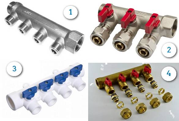
1. A comb for installing taps and any plumbing fixtures at your discretion.2. With compression fittings - designed for mounting pipes made of metal-plastic or cross-linked polyethylene.3. For installation of pipes from polypropylene.4. under the eurocone.Suitable for mounting pipes of almost any material through an adapter (Eurocone).
Separating combs differ in the number of taps. Minimum - 2 outlets, maximum - 6. Branches that are not currently used can be closed with plugs. If it is necessary to make more than 6 outputs, several collectors are interconnected.
Piping options
The main pipe laying patterns during installation are zigzag and spiral volutes, the latter provides more uniform heating and is considered the best in efficiency. When laying pipes, a certain distance between the sections should be maintained, it depends on the layout scheme and the thickness of the screed, its typical value for the usual thickness of the cement-sand layer lies in the range of 150 - 200 mm.
The distribution manifold is the main unit in an individual heating system containing two or more underfloor heating circuits, it performs the functions of distributing and mixing the coolant to reduce its temperature. During installation, a pipeline made of cross-linked or heat-resistant polyethylene is placed under the screed in the form of a zigzag or volute and connected to the combs using Eurocones, which provide a quick and tight connection.