- How LL starts with electronic ballast
- Lamp replacement
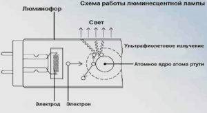
- The principle of operation of a fluorescent lamp
- What is a choke for?
- Differences between a choke and an electronic ballast
- Varieties of parts
- Schemes of electronic
- Electronic ballast circuit for fluorescent lamps with a power of 36 W
- Electronic ballast circuit based on a diode bridge for LDS with a power of 36 W
- Electronic ballast circuit for LDS with a power of 18 W
- Electronic ballast circuit based on a diode bridge for LDS with a power of 18 W
- Electronic ballast circuit in more expensive devices for LDS with a power of 21 W
- Power lamps from 12V
- Purpose of ballast
- Safety
- Cathode heating
- Ensuring a high level of voltage
- Current limitation
- Process stabilization
- Fluorescent lamp device
- Why do you need a choke in a fluorescent lamp
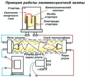
- Working principle of fluorescent lamp starter
- The principle of operation of a fluorescent lamp
- Lamp replacement
- Checking the technical condition of the starter
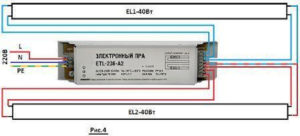
How LL starts with electronic ballast
Throttless switching on of fluorescent lamps is carried out through an electronic unit, in which a sequential change in voltage is formed when they are ignited.
Advantages of the electronic launch circuit:
- the ability to start with any time delay; no need for a massive electromagnetic choke and starter; no buzzing and blinking of the lamps; high light output; lightness and compactness of the device; longer service life.
Modern electronic ballasts are compact and have low power consumption. They are called drivers, placing them in the base of a small-sized lamp. The chokeless switching of fluorescent lamps allows the use of conventional standard lampholders.
The electronic ballast system converts the mains alternating voltage of 220 V to high frequency. First, the LL electrodes are heated, and then a high voltage is applied.
At a high frequency, efficiency is increased and flicker is completely eliminated. The fluorescent lamp switching circuit can provide a cold start or a smooth increase in brightness. In the first case, the service life of the electrodes is significantly reduced.
Increased voltage in the electronic circuit is created through an oscillatory circuit, leading to resonance and ignition of the lamp. Starting is much easier than in the classical circuit with an electromagnetic choke. Then the voltage is also reduced to the required discharge holding value.
The voltage is rectified by a diode bridge, after which it is smoothed out by a parallel-connected capacitor C1. After connecting to the network, the capacitor C4 immediately charges and the dinistor breaks through. The half-bridge generator starts on the transformer TR1 and transistors T1 and T2. When the frequency reaches 45-50 kHz, a resonance is created using the serial circuit C2, C3, L1 connected to the electrodes, and the lamp lights up.
This circuit also has a choke, but with very small dimensions, allowing it to be placed in the lamp base. The electronic ballast has an automatic adjustment to the LL as the characteristics change. After a while, a worn-out lamp requires a boost in voltage to ignite. In the EMPRA circuit, it simply will not start, and the electronic ballast adjusts to the change in characteristics and thereby allows the device to be operated in favorable modes. The advantages of modern electronic ballasts are as follows: .Disadvantages are higher cost and complicated ignition scheme.
Lamp replacement
If there is no light and the cause of the problem is only to replace a burnt out light bulb, you need to proceed as follows:
We disassemble the lamp
We do this carefully so as not to damage the device. Rotate the tube along the axis
The direction of movement is indicated on the holders in the form of arrows.
When the tube is rotated 90 degrees, lower it down. The contacts should come out through the holes in the holders.
The contacts of the new light bulb should be in a vertical plane and fall into the hole. When the lamp is installed, turn the tube in the opposite direction. It remains only to turn on the power supply and check the system for operability.
The final step is the installation of a diffuser ceiling.
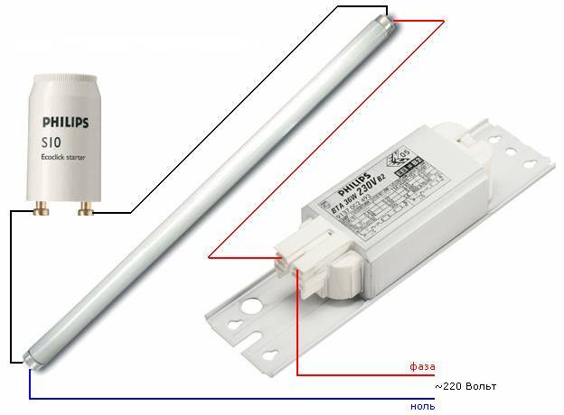
The principle of operation of a fluorescent lamp
A feature of the operation of fluorescent lamps is that they cannot be directly connected to the power supply.The resistance between the electrodes in the cold state is large, and the amount of current flowing between them is insufficient for a discharge to occur. Ignition requires a high voltage pulse.
A lamp with an ignited discharge is characterized by low resistance, which has a reactive characteristic. To compensate for the reactive component and limit the flowing current, a choke (ballast) is connected in series with the luminescent light source.
Many do not understand why a starter is needed in fluorescent lamps. The inductor, included in the power circuit together with the starter, generates a high voltage pulse to start a discharge between the electrodes. This happens because when the starter contacts are opened, a self-induction EMF pulse of up to 1 kV is formed at the inductor terminals.
What is a choke for?
The use of a choke for fluorescent lamps (ballast) in power circuits is necessary for two reasons:
- starting voltage generation;
- limiting the current through the electrodes.
The principle of operation of the inductor is based on the reactance of the inductor, which is the inductor. Inductive reactance introduces a phase shift between voltage and current equal to 90º.
Since the current-limiting quantity is inductive reactance, it follows that chokes designed for lamps of the same power cannot be used to connect more or less powerful devices.
Tolerances are possible within certain limits. So, earlier, the domestic industry produced fluorescent lamps with a power of 40 watts. A 36W inductor for modern fluorescent lamps can be safely used in power circuits of outdated lamps and vice versa.
Differences between a choke and an electronic ballast
The throttle circuit for switching on luminescent light sources is simple and highly reliable. The exception is the regular replacement of starters, since they include a group of NC contacts for generating start pulses.


At the same time, the circuit has significant drawbacks that forced us to look for new solutions for turning on lamps:
- long start-up time, which increases as the lamp wears out or the supply voltage decreases;
- large distortion of the mains voltage waveform (cosf
- flickering glow with double the frequency of the power supply due to the low inertia of the luminosity of the gas discharge;
- large weight and size characteristics;
- low-frequency hum due to vibration of the plates of the magnetic throttle system;
- low reliability of starting at low temperatures.
Checking the choke of fluorescent lamps is hampered by the fact that devices for determining short-circuited turns are not very common, and using standard devices, one can only state the presence or absence of a break.
To eliminate these shortcomings, schemes have been developed electronic ballast equipment (electronic ballast). The operation of electronic circuits is based on a different principle of generating a high voltage to start and maintain combustion.
The high voltage pulse is generated by the electronic components and a high frequency voltage (25-100 kHz) is used to support the discharge. The operation of the electronic ballast can be carried out in two modes:
- with preliminary heating of electrodes;
- with cold start.
In the first mode, low voltage is applied to the electrodes for 0.5-1 second for initial heating.After the time has elapsed, a high-voltage pulse is applied, due to which the discharge between the electrodes is ignited. This mode is technically more difficult to implement, but increases the service life of the lamps.
The cold start mode is different in that the start voltage is applied to the cold electrodes, causing a quick start. This starting method is not recommended for frequent use, as it greatly reduces the life, but it can be used even with lamps with faulty electrodes (with burnt filaments).
Circuits with an electronic choke have the following advantages:
complete absence of flicker;
wide temperature range of use;
small distortion of the mains voltage waveform;
absence of acoustic noise;
increase the service life of lighting sources;
small dimensions and weight, the possibility of miniature execution;
the possibility of dimming - changing the brightness by controlling the duty cycle of the electrode power pulses.
Varieties of parts
For the right choice, you need to know the technical characteristics of various models. Properly selected parts will not cause trouble in operation. These types of igniters are especially popular these days:
- Smoldering row. Used in lamps with bimetallic electrodes. They are often bought because of the simplified design. In addition, the ignition time is short.
- Thermal. Characterized by a longer ignition period of the light source. The electrodes heat up longer, but this has a positive effect on performance.
- Semiconductor. They operate on the principle of a key. After heating, the electrodes open, then a pulse is formed in the flask and the bulb lights up.
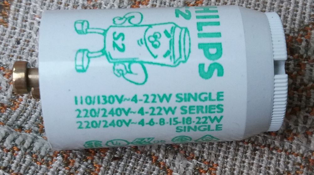
So, parts from Philips Corporation are classified as smoldering. They are of the highest quality. Case material - fire-resistant polycarbonate. These igniters have built-in capacitors. The production process does not use harmful isotopes. Installation is carried out using a conventional screwdriver.
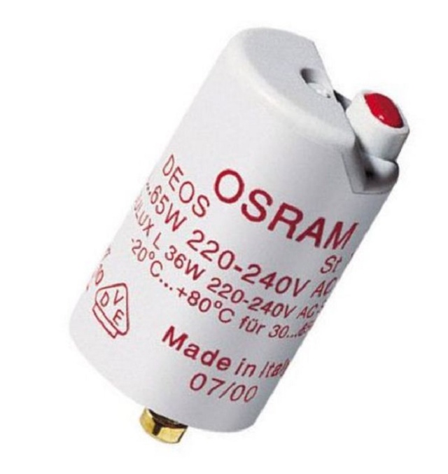
OSRAM products are characterized by the presence of a dielectric non-flammable housing made of macrolon. They additionally have capacitors that suppress interference (foil roll).
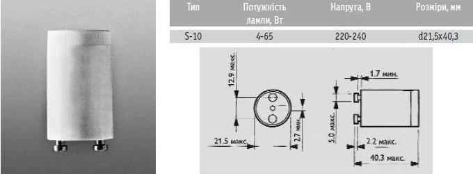
Popular and S models: S-2 and S-10. The former are used when igniting low-voltage models with a power of up to 22 watts. The second is for ignition of high-voltage lamps of fluorescent structures with a wide power range (4–64 W).
The starter is one of the main components of the lamps. Its correct choice will be the key to a long and trouble-free operation of such light sources.
Schemes of electronic
Depending on the type of a particular light bulb, electronic ballast elements can have different implementations, both in terms of electronic filling and in terms of embedding. Below we will consider several options for devices with different power and design.
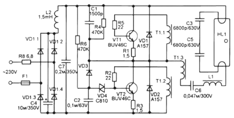
Electronic ballast circuit for fluorescent lamps with a power of 36 W
Depending on the electronic components used, the electrical circuit of the ballasts may differ significantly by type and technical parameters, but the functions they perform will be the same.
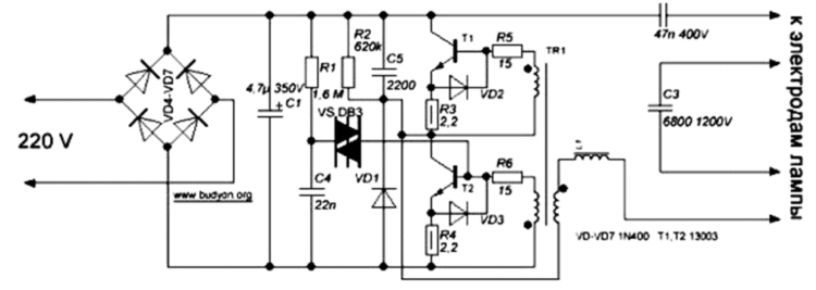
In the figure above, the diagram uses the following elements:
- diodes VD4-VD7 are designed to rectify the current;
- capacitor C1 is designed to filter the current passing through the system of diodes 4-7;
- capacitor C4 starts charging after voltage is applied;
- dinistor CD1 breaks through at the moment the voltage reaches 30 V;
- transistor T2 opens after breaking through 1 dinistor;
- transformer TR1 and transistors T1, T2 are started as a result of activation of the oscillator on them;
- generator, inductor L1 and series capacitors C2, C3 at a frequency of approximately 45-50 kHz begin to resonate;
- capacitor C3 turns on the lamp after it reaches the starting charge value.
Electronic ballast circuit based on a diode bridge for LDS with a power of 36 W
In the above scheme, there is one feature - the oscillatory circuit is built into the design of the lighting device itself, which ensures the resonance of the device until a discharge appears in the bulb.
Thus, the filament of the lamp will act as part of the circuit, which at the moment the discharge appears in the gaseous medium is accompanied by a change in the corresponding parameters in the oscillatory circuit. This brings it out of resonance, which is accompanied by a decrease to the operating voltage level.


Electronic ballast circuit for LDS with a power of 18 W
Lamps that are equipped with an E27 and E14 base today are most widely used among consumers. In this device, the ballast is built directly into the design of the device. The corresponding diagram is shown above.
Electronic ballast circuit based on a diode bridge for LDS with a power of 18 W
It is necessary to take into account the peculiarity of the structure of the oscillator, which is based on a pair of transistors.
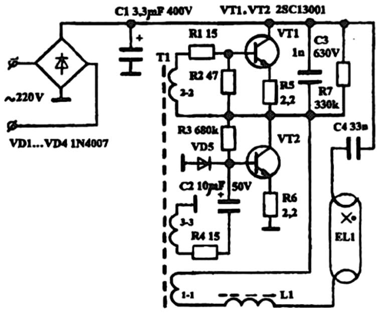
From the step-up winding, indicated in the diagram 1-1 of the transformer Tr, power is supplied. The parts of the series oscillatory circuit are the inductor L1 and the capacitor C2, the resonant frequency of which differs significantly from that generated by the oscillator. The above diagram is used for budget-class desktop lighting fixtures.
Electronic ballast circuit in more expensive devices for LDS with a power of 21 W
It should be noted that simpler ballast circuits, which are used for LDS-type lighting fixtures, cannot guarantee long-term operation of the lamp, since they are subjected to heavy loads.
For expensive products, such a circuit ensures stable operation throughout the entire operational period, since all elements used meet more stringent technical requirements.
Power lamps from 12V
But lovers of homemade products often ask the question “How to light a fluorescent lamp from low voltage?”, We found one of the answers to this question. To connect the fluorescent tube to a low-voltage DC source, such as a 12V battery, you need to assemble a boost converter. The simplest option is a 1-transistor self-oscillating converter circuit. In addition to the transistor, we need to wind a three-winding transformer on a ferrite ring or rod.
Such a scheme can be used to connect fluorescent lamps to the vehicle's on-board network. It also does not need a throttle and a starter for its operation. Moreover, it will work even if its spirals are burned out. Perhaps you will like one of the variations of the considered scheme.
Starting a fluorescent lamp without a choke and starter can be carried out according to several considered schemes. This is not an ideal solution, but rather a way out of the situation.A luminaire with such a connection scheme should not be used as the main lighting of workplaces, but it is acceptable for lighting rooms where a person does not spend much time - corridors, storerooms, etc.
You probably don't know:
- Advantages of electronic ballast over empra
- What is a choke for?
- How to get a voltage of 12 volts
Purpose of ballast
Mandatory electrical characteristics of a daylight luminaire:
- Consumed current.
- starting voltage.
- Current frequency.
- Current crest factor.
- Illumination level.
The inductor provides a high initial voltage to initiate the glow discharge and then quickly limits the current to safely maintain the desired voltage level.
The main functions of the ballast transformer are discussed below.
Safety
The ballast regulates the AC power for the electrodes. When alternating current passes through the inductor, the voltage rises. At the same time, the current strength is limited, which prevents a short circuit, which leads to the destruction of the fluorescent lamp.


Cathode heating
For the lamp to work, a high voltage surge is necessary: it is then that the gap between the electrodes breaks down, and the arc lights up. The colder the lamp, the higher the required voltage. The voltage "pushes" the current through the argon. But the gas has a resistance, which is higher, the colder the gas. Therefore, it is required to create a higher voltage at the lowest possible temperatures.
To do this, you need to implement one of two schemes:
- using a starting switch (starter) containing a small neon or argon lamp with a power of 1 W.It heats the bimetallic strip in the starter and facilitates the initiation of a gas discharge;
- tungsten electrodes through which current passes. In this case, the electrodes heat up and ionize the gas in the tube.
Ensuring a high level of voltage
When the circuit is broken, the magnetic field is interrupted, a high voltage pulse is sent through the lamp, and a discharge is initiated. The following high voltage generation schemes are used:
- Preheating. In this case, the electrodes are heated until the discharge is initiated. The start switch closes, allowing current to flow through each electrode. The starter switch cools rapidly, opening the switch and starting the supply voltage on the arc tube, resulting in a discharge. During operation, no auxiliary power is supplied to the electrodes.
- Quick start. The electrodes heat up constantly, so the ballast transformer includes two special secondary windings that provide a low voltage on the electrodes.
- Instant start. The electrodes do not heat up before starting work. For instant starters, the transformer provides a relatively high starting voltage. As a result, the discharge is easily excited between the "cold" electrodes.
Current limitation
The need for this arises when a load (for example, an arc discharge) is accompanied by a voltage drop at the terminals when the current increases.
Process stabilization
There are two requirements for fluorescent lamps:
- to start the light source, a high voltage jump is needed to create an arc in mercury vapor;
- once the lamp is started, the gas offers decreasing resistance.
These requirements vary depending on the power of the source.
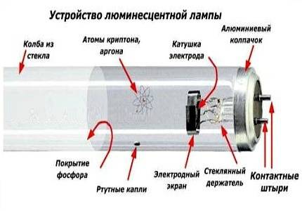
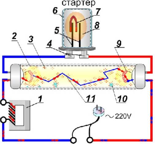
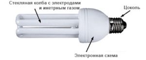
Fluorescent lamp device
Welded glass legs are located on the two ends of the fluorescent lamp in Fig. 2, electrodes 5 are mounted on each leg, the electrodes are led to the base 2 and connected to the contact pins, a tungsten spiral is fixed on the electrodes themselves on both ends of the lamp.
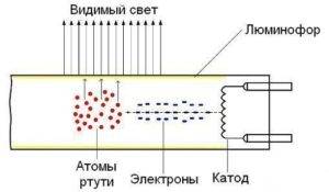
A thin layer of phosphor 4 is deposited on the inner surface of the lamp, the bulb of lamp 1 is filled with argon with a small amount of mercury 3 after evacuation of air.
Why do you need a choke in a fluorescent lamp
The inductor in the circuit of a fluorescent lamp serves to inject voltage. Consider a separate electrical circuit in Fig. 3, which does not apply to the circuit of a fluorescent lamp.
For this circuit, when the key is opened, the lamp will light up brighter for a short moment and then go out. This phenomenon is connected with the occurrence of the self-inductance EMF of the coil, the Lenz rule. To increase the properties of the manifestation of self-induction, the coil is wound on a core - to increase the electromagnetic flux.
The schematic representation of Figure 4 gives us a complete picture of the choke design for individual types of luminaires with fluorescent lamps.
The magnetic core of the inductor is assembled from plates of electrical steel, two windings in the inductor are connected in series to each other.
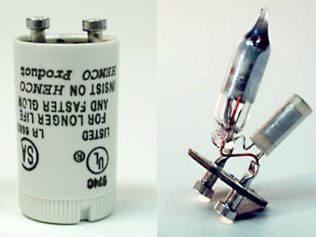
Working principle of fluorescent lamp starter
The starter in the electrical circuit performs the work of a high-speed key, that is, it creates a closing and opening of the electrical circuit.
starters for fluorescent lamps
When the starter is turned on, the key is closed, the cathodes are heated, and when the circuit is opened, a voltage pulse is created that is necessary to ignite the lamp. The disassembled starter is a so-called glow discharge lamp with bimetallic electrodes.
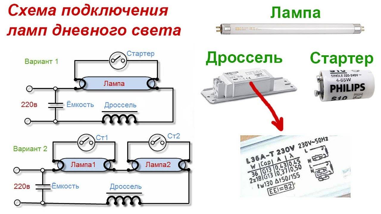
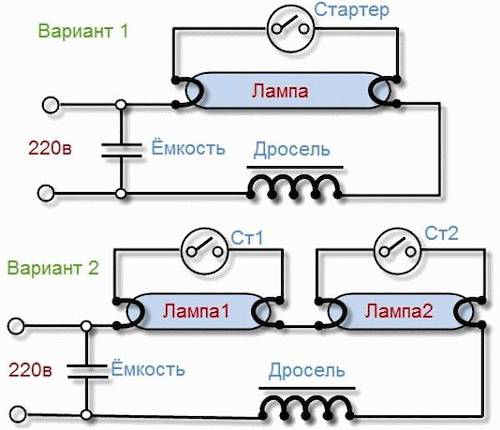
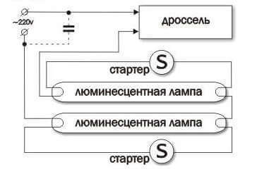
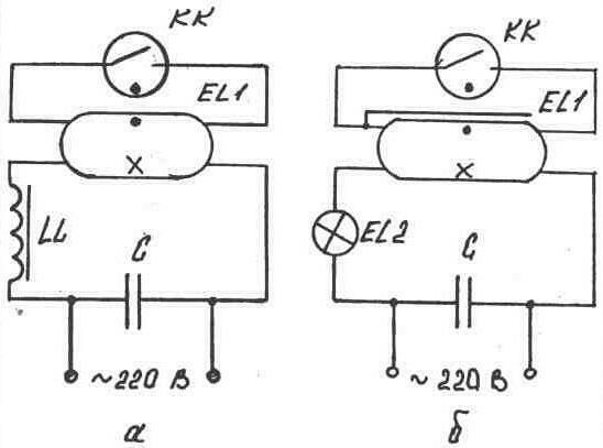
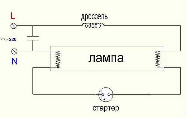
The principle of operation of a fluorescent lamp
According to the two diagrams of fluorescent lamps provided in Fig. 5, one can understand what connection each individual element consists of.


All elements of the two lamps are connected in series, except for the capacitors. When we turn on the fluorescent lamp, the starter bimetallic plate is heated. When the plate is heated, it bends and the starter closes, the glow discharge, when the plates are closed, goes out and the plates begin to cool, when cooling, the plates open. When the plates open in mercury vapor, an arc discharge occurs and the lamp ignites.
Currently, there are more advanced fluorescent lamps - with electronic ballast, the principle of operation of which is the same as that of the fluorescent lamps that were discussed in this topic.
The notes provided for you are entered by me into the site from personal notes, the handwriting in which is very poor, some of the information is taken from my own knowledge. Photographs and electrical circuits are selected for the topic - from the Internet. To provide your notes with personal photographs when doing any work, you probably need to have a personal photographer or directly ask someone, but you just don’t want to make such a request.
That's all friends for now.Follow the rubric.
03/04/2015 at 16:41
I will always help Boris with useful information on electrical engineering for both you and your friends and acquaintances. Victor.
26.02.2015 at 08:58
Hello Victor! Thanks for the email, it helps! I have such a case: first one ceiling lamp built into the Armstrong system went out, then another. I turned to a specialist for help and received an answer: the lamps must be thrown away and replaced with new ones as a whole, because. now there are lamps without starters, etc. I replaced the lamps and thought that this way is very expensive, a new lamp costs 1400 rubles. If possible, please tell me how to check the filling of the lamp? chokes, starters, capacitor. A 4-lamp lamp, with 4 starters, two chokes, one capacitor, in other words, how to find a faulty device? I have a tester. And yet, in which store can you buy the components of the filling in Tyumen? Thank you in advance. Thank you. Boris. 02/26/15.
03/04/2015 at 16:35
Hello Boris. On fluorescent lamps, I will make an additional separate topic and answer your questions. Follow the column Boris, I just began to rarely visit my site and read your letter on March 4, I will try to answer the questions in full.
17.03.2015 at 12:57
Lamp replacement
Like other light sources, fluorescent devices fail. The only way out is to replace the main element.
Replacing the fluorescent lamp
The replacement process using the Armstrong ceiling lamp as an example:
Carefully disassemble the lamp. Taking into account the arrows indicated on the body, the flask rotates along the axis.
By turning the flask 90 degrees, you can lower it down.The contacts will shift and come out through the holes.
Place a new flask in the groove, making sure that the contacts fit into the corresponding holes
Turn the installed tube in the opposite direction. Fixation is accompanied by a click.
Turn on the light fixture and check if it works.
Assemble the body and install the diffuser cover.
The contacts will shift and come out through the holes.
Place a new flask in the groove, making sure that the contacts fit into the corresponding holes. Turn the installed tube in the opposite direction. Fixation is accompanied by a click.
Turn on the light fixture and check if it works.
Assemble the body and install the diffuser cover.
If the newly installed bulb burned out again, it makes sense to check the throttle. Perhaps it is he who supplies too much voltage to the device.
Checking the technical condition of the starter
In the event of any malfunction of a lighting device with fluorescent lamps, it is very often necessary to separately check the performance of the starter. In the general design, it is defined as a fairly simple part with small dimensions. Breakdown of the starter brings a lot of problems, primarily associated with the termination of the entire lamp.
A common cause of a malfunction is a worn glow lamp or a bimetallic contact plate. Outwardly, this is manifested by a failure at startup or flashing during operation. The device does not start on the second attempt, or on subsequent ones, because there is not enough voltage to start the entire lamp.
The easiest way to check is to completely replace the starter with another device of the same type.If after that the lamp turns on normally and works, then the reason was precisely in the starter. In this situation, measuring instruments are not required, however, in the absence of a spare part, it will be necessary to create a simple test circuit with a serial connection of the starter and incandescent lamp. After that, connect the 220 V power supply through the socket.


For such a circuit, low-power bulbs of 40 or 60 watts are best suited. After turning on, they light up, and then, with a click, periodically turn off for a short time. This indicates the health of the starter and the normal operation of its contacts. If the light is on constantly and does not blink, or it does not light up at all, then the starter is not working and needs to be replaced.
In most cases, you can get by with just one replacement, and the lamp will work again. However, if the starter is exactly OK, but the lamp still does not work, it is necessary to check the throttle and other components of the circuit in series.
Fluorescent lamp circuit
Why is the fluorescent lamp flashing
Types of fluorescent lamps
Fluorescent lamp connection diagram
Electronic ballast for fluorescent lamps


