- Functional foundations and basic varieties of collectors
- With fittings for connecting circuits
- With integrated taps
- with control valves
- Assembly from supply and return manifolds
- Functions: basic and additional
- Additional collector devices
- Automatic temperature control device
- Collector selection rules
- Self-assembly of the heating manifold
- Collector-beam heating system
- Criterias of choice
- Video description
- Assembly and installation
- Video description
- Briefly about the main
- Rules for installing a collector for underfloor heating
- Video installation instructions
- Recommendations and advice
Functional foundations and basic varieties of collectors
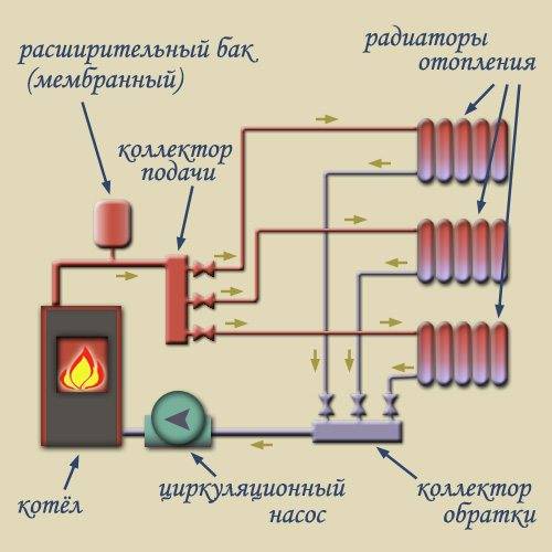
The scheme of operation of the collector for a warm floor is quite simple. The heat carrier from the heating boiler enters the supply distributor. It is recommended to place it on top (above the return comb), however, depending on local installation features, as well as the type of connected mixing unit, it can also be installed below. The collector housing has two or more branches equipped with appropriate shut-off and control valves. For each of the branches, the coolant is redirected to certain TP pipelines. The outlet end of the pipe loop closes on the return manifold, which directs the collected total flow to the heating boiler.
Obviously, in the simplest case, a collector for a water-heated floor is a piece of pipe with a certain number of threaded outlets. However, depending on what final configuration it will receive, the complexity of its assembly, settings and cost can vary significantly. Let us first consider the most popular basic models of distributors for water TS.
With fittings for connecting circuits
One of the most budgetary, but completely ready-to-use, is a comb with inlet / outlet threads and fittings for connecting metal-plastic or XLPE pipes. One of these models is shown in the photo below.
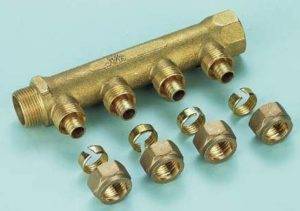 Figure 2.
With integrated taps
In the minimum configuration, you can also find a collector for underfloor heating equipped with two-way ball valves (Fig. 3). Such devices do not provide for contour adjustment - they are designed only to turn on or off individual heating branches. Given that the underfloor heating system is purchased and installed to increase the comfort of residents, which is ensured by fine tuning of the system, the expediency of using such combs is purely selective. The photo shows a similar manifold for three circuits with integrated two-way ball valves.
When purchasing these budget options for distributors, it should be borne in mind that their use requires fundamental knowledge, as well as extensive experience in installing heating systems. In addition, the procurement savings are rather conditional, since all additional equipment will have to be purchased separately.Practically simplified collectors for a warm water floor without modification are only suitable for auxiliary systems for one or two small loops. They are also suitable for several circuits, but having identical thermal and hydraulic characteristics. After all, the design of such combs does not provide the technical possibility of installing control and regulation equipment directly on each branch.
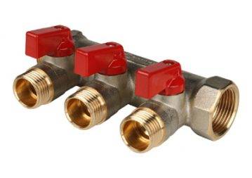 Figure 3
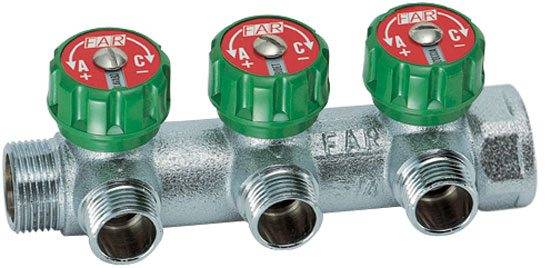
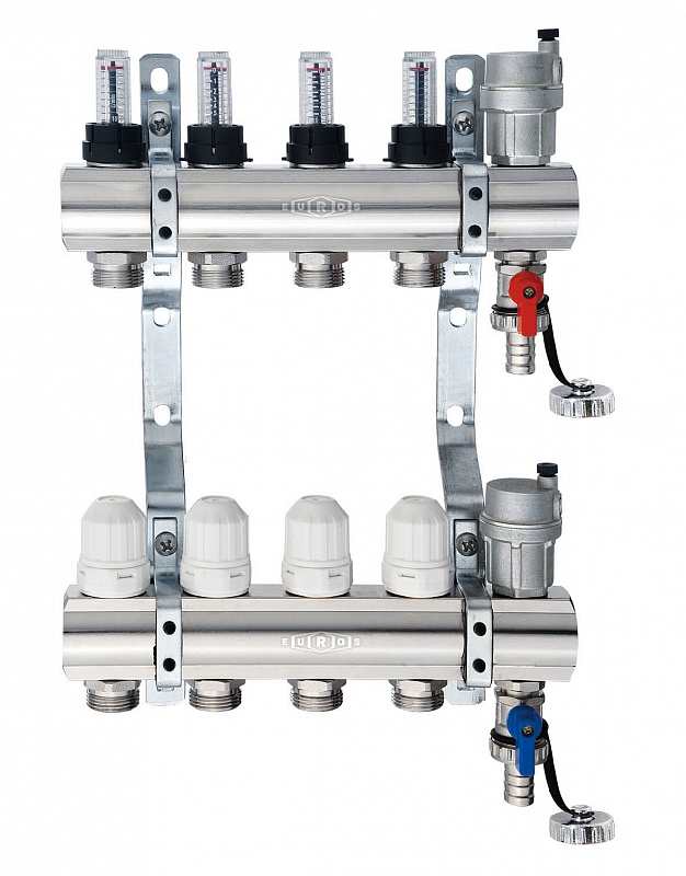
with control valves
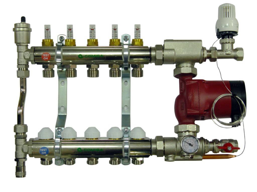
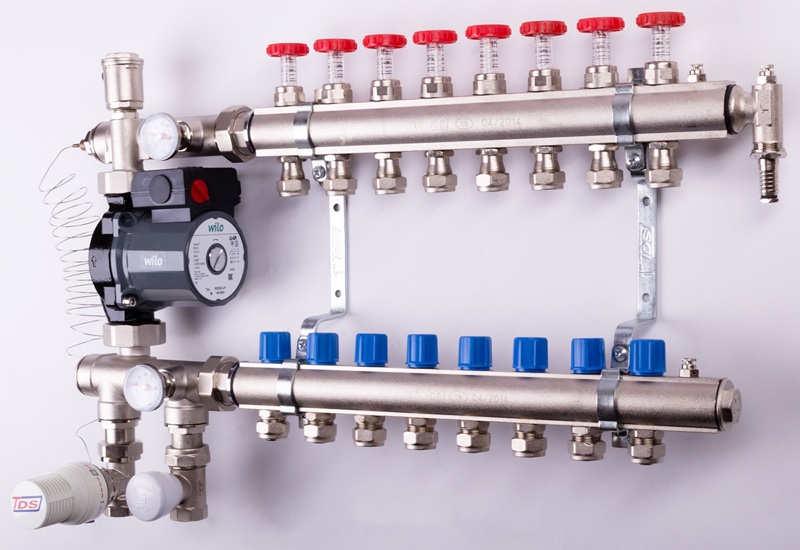
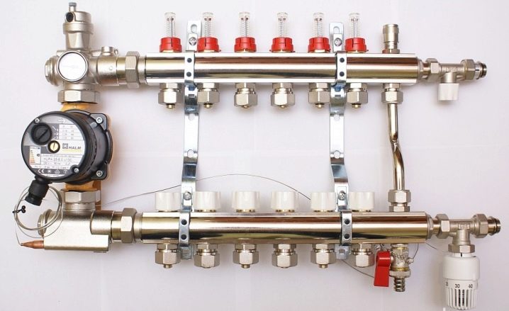
The next level, both in terms of cost and functionality, is a distribution manifold for underfloor heating with control valves. Such devices, operated in manual mode, can already provide adjustment of the intensity of the coolant supply for individual heating circuits. For them, in most cases, it is technically possible to install actuators with servo drives instead of manual valves. The actuators can be connected either directly to electronic temperature sensors installed in the premises or to a central programmable control unit. Figure 4 shows an example of a manifold with control valves.
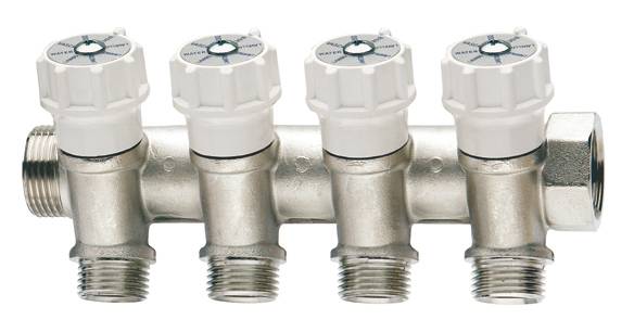 Figure 4
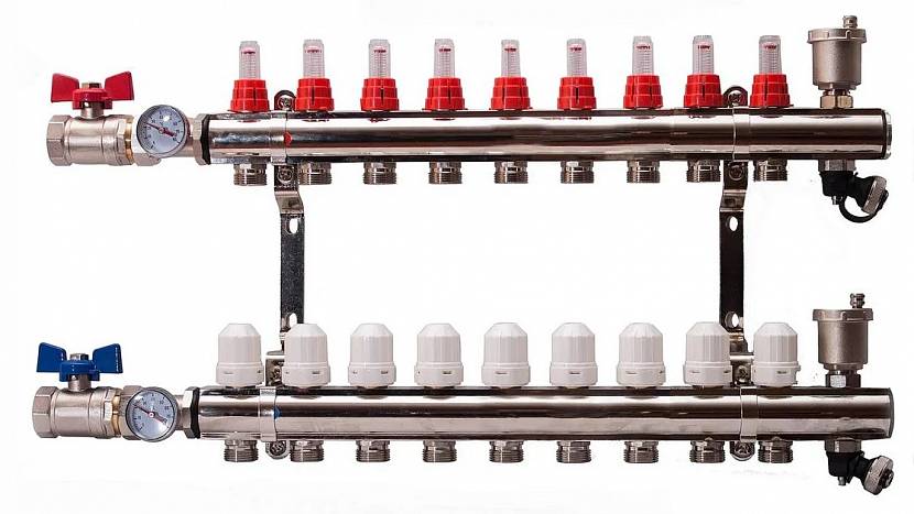
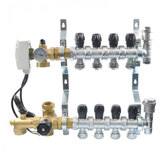
Assembly from supply and return manifolds
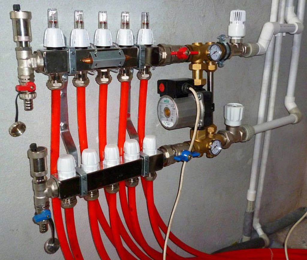
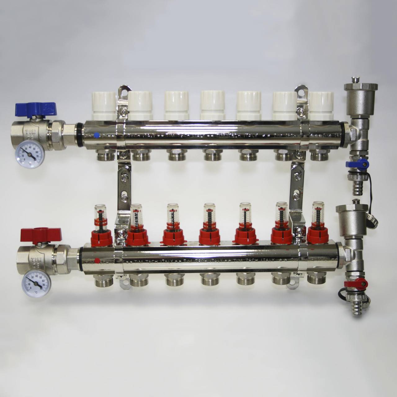
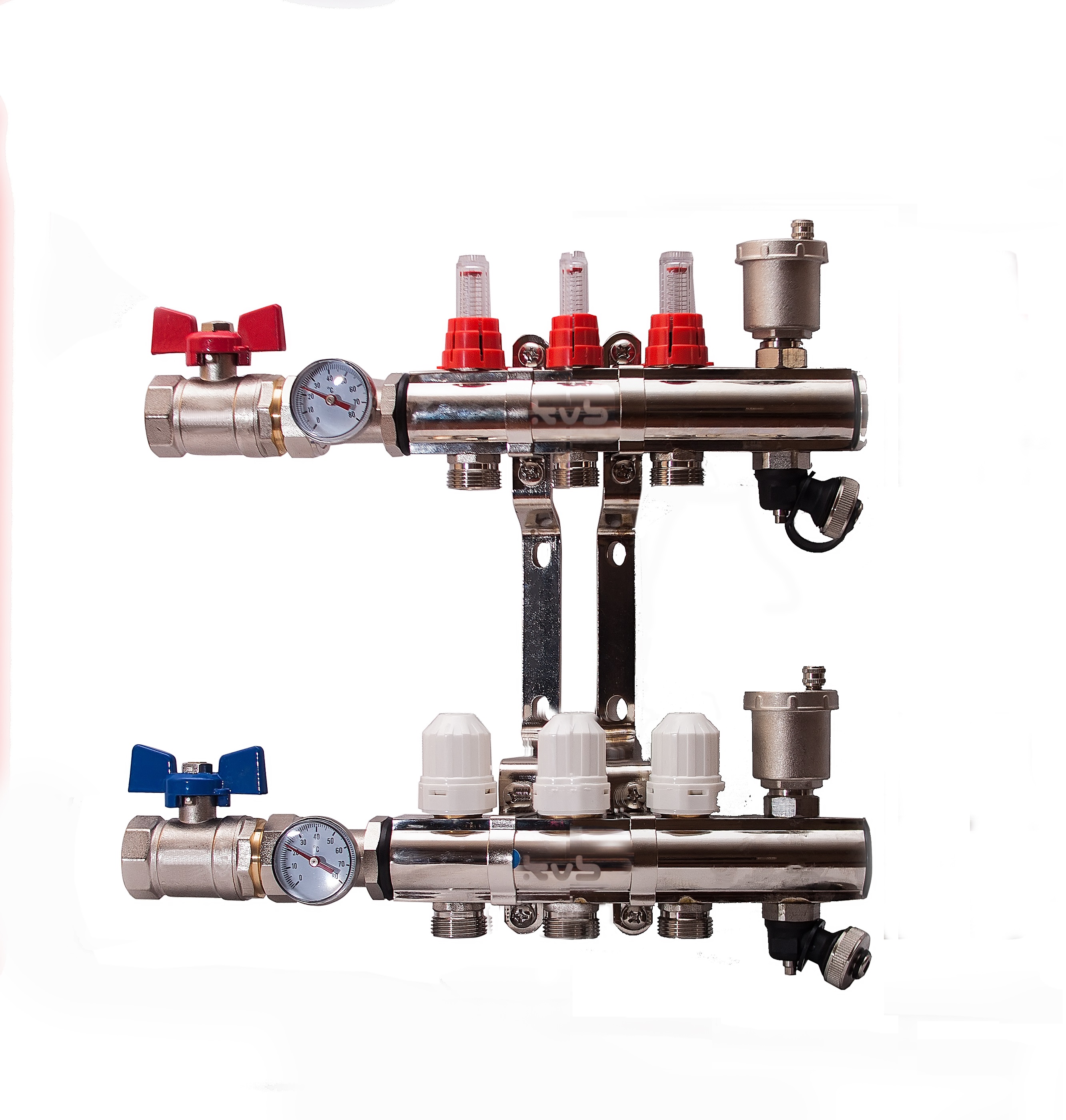
The economy version of the collector for a warm water floor also includes paired assemblies from the supply and return distributors (Fig. 5). They may already have additional mounting holes or Mayevsky taps, safety groups, quick-release threaded "American" for easy connection to the primary heating circuits or the mixing unit.
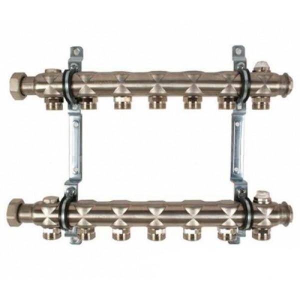 Figure 5
Functions: basic and additional
The distribution of the coolant along the circuits is the main task of the underfloor heating collector, but it can still perform a lot of additional functions. For example, most often there are two shut-off valves in the manifold: on the supply and on the "return". Through them, the system is filled with coolant, tested (pressurized) and drained. The collectors are also equipped with bleed valves through which air exits the system. These are general devices.
The underfloor heating collector distributes the hot coolant from the supply comb, and collects the “return” that has cooled on the comb
Additional collector devices
There are also extras on the collectors. devices that are installed on each contour or loop of the warm floor. The most commonly used flow meters. They are installed on the supply comb and serve to equalize the hydraulic resistance of the underfloor heating loops of different lengths. In all instructions, it is recommended that the floor heating circuits be made the same length. In practice, this is often unrealistic. But if you connect a circuit of different lengths directly to the distribution, then most of the flow will go through the shortest one, because it has the smallest hydraulic resistance. To prevent this from happening, install flow meters. With their help, the flows in each loop of the warm floor are regulated, narrowing / expanding the clearance for the passage of the coolant.
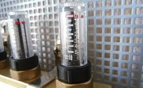
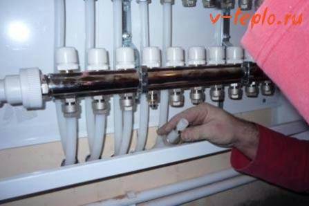
This is what the meters look like. When the system starts, they are filled with air, then a coolant may appear in them. It's normal, it doesn't interfere with work.
On the return manifold, at the outlet of each circuit, there are shut-off valves. With their help, one or more heating circuits can be switched off. And thus regulate the temperature of the floor and / or air in the room.You can also do this with a flow meter, reducing the coolant flow if it becomes too hot, increasing it if it is frozen.
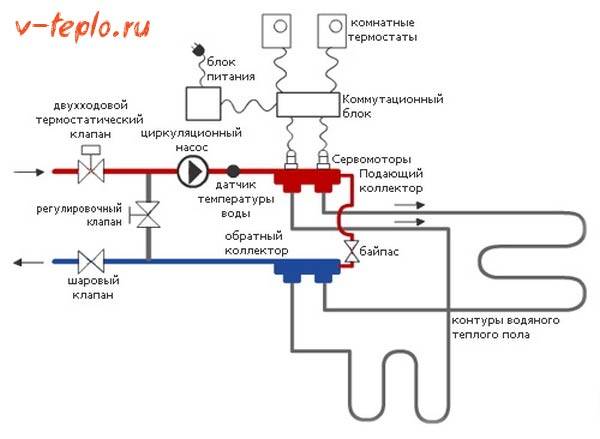
Automatic temperature control device
Of course, you can regulate the heat transfer and so, by hand, but you can leave this matter to automation. Then in place of manual consumables valves on the return manifold servomotors, and a thermostat (thermostat), conventional or programmable, is placed in the room.
Thermostats can control the temperature of the air in the room, or they can control the temperature of the warm floor. The temperature of the warm floor is controlled by a remote sensor, which is connected to the thermostat. The sensor must be installed before pouring the screed.
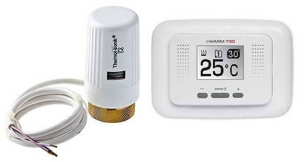
Thermostat and servo drive for water heating. One of many options
To install a sensor that controls the temperature of the floor, a strobe is punched down in the wall from the thermostat down. A corrugated hose is placed in it, which should go to the floor and end at a distance of at least 50 cm from the wall. Moreover, the end of the corrugated hose should be located between the pipes, and not closer to one of them - so its readings will be more accurate. When laying the corrugation, try to keep the turns as small as possible, and all of them were smooth.


The end of the corrugation that is in the screed must be sealed so that the solution does not get into it when pouring the screed. You can wrap it well with electrical tape or make a cork out of foam. This whole procedure is necessary so that the floor temperature sensor can be pulled out and changed if necessary.
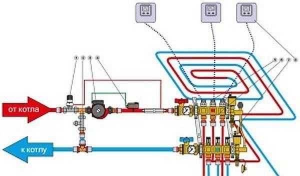
This is how the connection diagram with a two-way valve, control from a thermostat and servos may look like
Let's put the sensor in place. To do this, from the end of the corrugated hose, which is located near the thermostat, simply lower the sensor (it is attached to a long wire) until it stops. If the wire is too soft and the sensor won't go through the turn, try using a thick garden line as a broach. This usually helps.
When using sensors, a constant temperature will be maintained automatically. The control mechanism in this case is simple. You set the desired temperature on the thermostat. If the actual air temperature deviates from the set one by 1°C, the corresponding servomotor is given a command to turn on/off the coolant supply.
Collector selection rules
The collector for a warm water floor can be assembled by hand or bought ready-made
In the first case, it is important that all components are produced by one manufacturer. Some companies produce unique connectors that do not fit with parts from other suppliers, which threatens the assembled assembly with loss of tightness. In the second case, when choosing equipment, you need to consider several important points.
First of all, you need to decide on the material from which the collector is made. It could be:
In the second case, when choosing equipment, you need to consider several important points. First of all, you need to decide on the material from which the collector is made. It could be:
- copper;
- steel;
- brass;
- polymer.
In addition, the collectors differ in the number of connected circuits, the number of which can vary from 2 to 12. The choice of device is based on an accurate calculation of the main parameters of the system and the required additional functions. Be sure to take into account:
- the number of heating circuits, their length and throughput;
- maximum pressure;
- the ability to add branches;
- the presence of elements that automatically control the operation of the device;
- the amount of electricity consumed;
- collector inner diameter.
The latter indicator should be selected so as to ensure the maximum permeability of the coolant in all heating circuits. The efficiency of the unit largely depends on the laying step, diameter and length of the pipes included in the heating circuit.
At the design stage of the system, these parameters must also be calculated. This is a rather laborious undertaking, which is best entrusted to specialists. You can make the calculation in a special calculator program, which can be found on the Internet.
When making calculations, it is very important to take into account all the parameters of the system. Otherwise, it will work unproductively: insufficient circulation of the coolant or its leakage is possible, and a “thermal zebra” may also appear, as experts call uneven heating of the surface. To correctly determine the length of the contour and the pipe laying step, the following data will be required:
To correctly determine the length of the contour and the pipe laying step, the following data will be required:
- type of finish flooring;
- area of the room with a plan for arranging large furniture and household appliances;
- pipe diameter and material;
- heating boiler power;
- type of insulation used.
When calculating, we must take into account that there should not be pipe joints in the circuit, since the use of couplings and connections under a concrete screed is strictly prohibited.In addition, we take into account the hydraulic resistance of the coolant, which will increase with each turn of the branch and as its length increases.
It is optimal if only circuits of equal length will be connected to one collector. Perhaps the best solution for long branches is to divide them into several smaller ones.
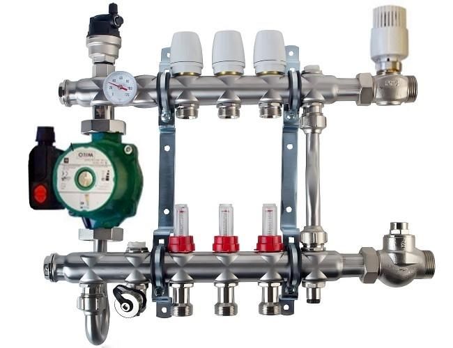
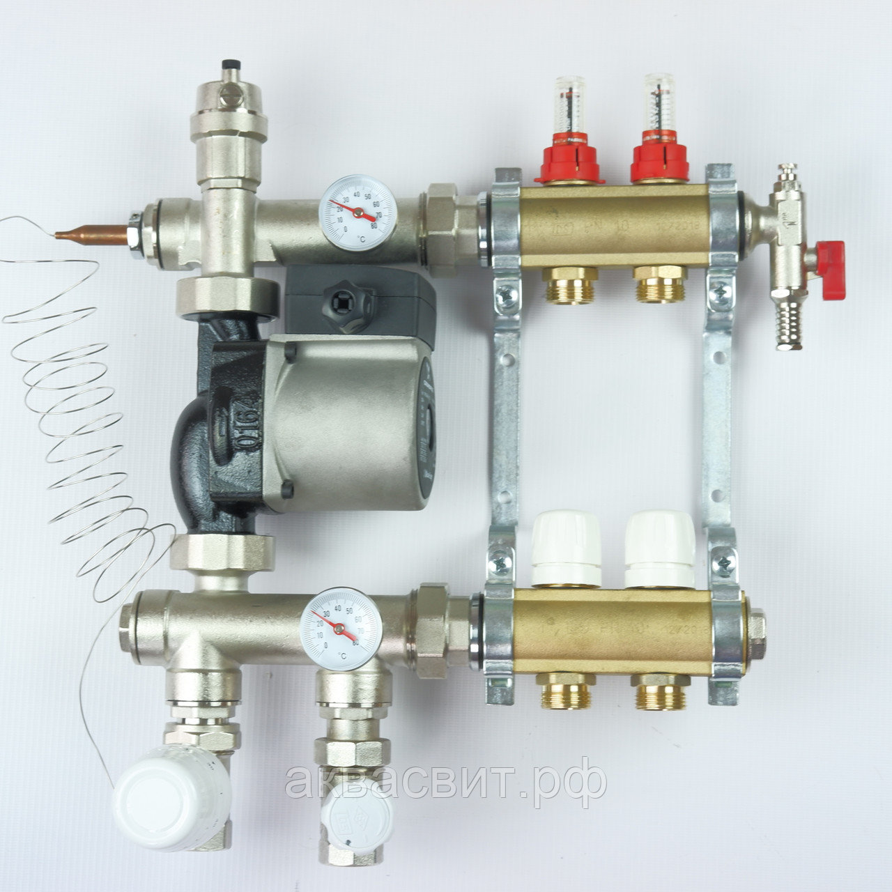
Self-assembly of the heating manifold
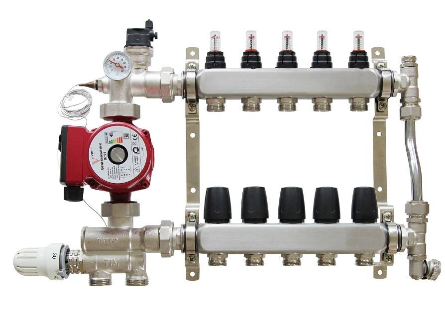
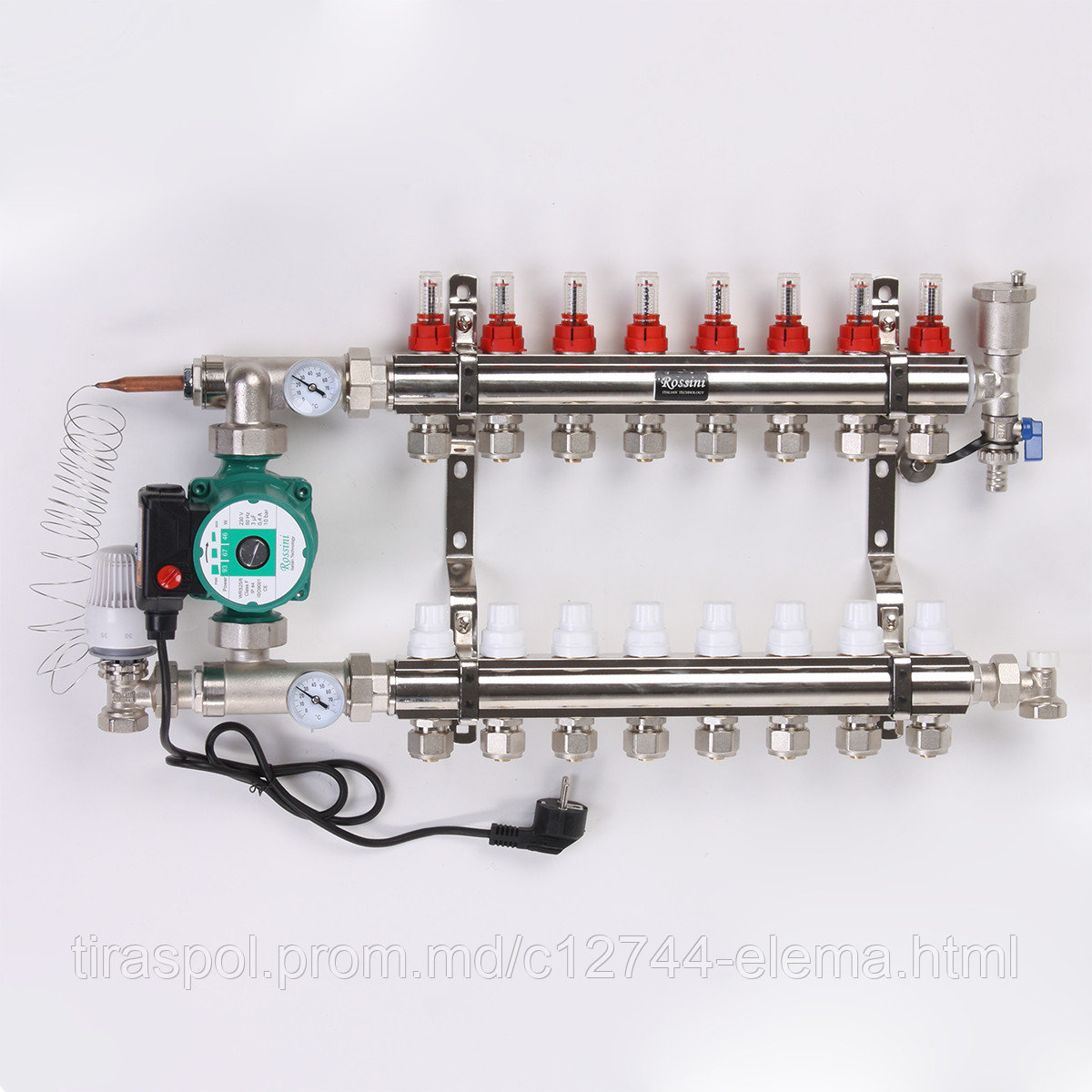
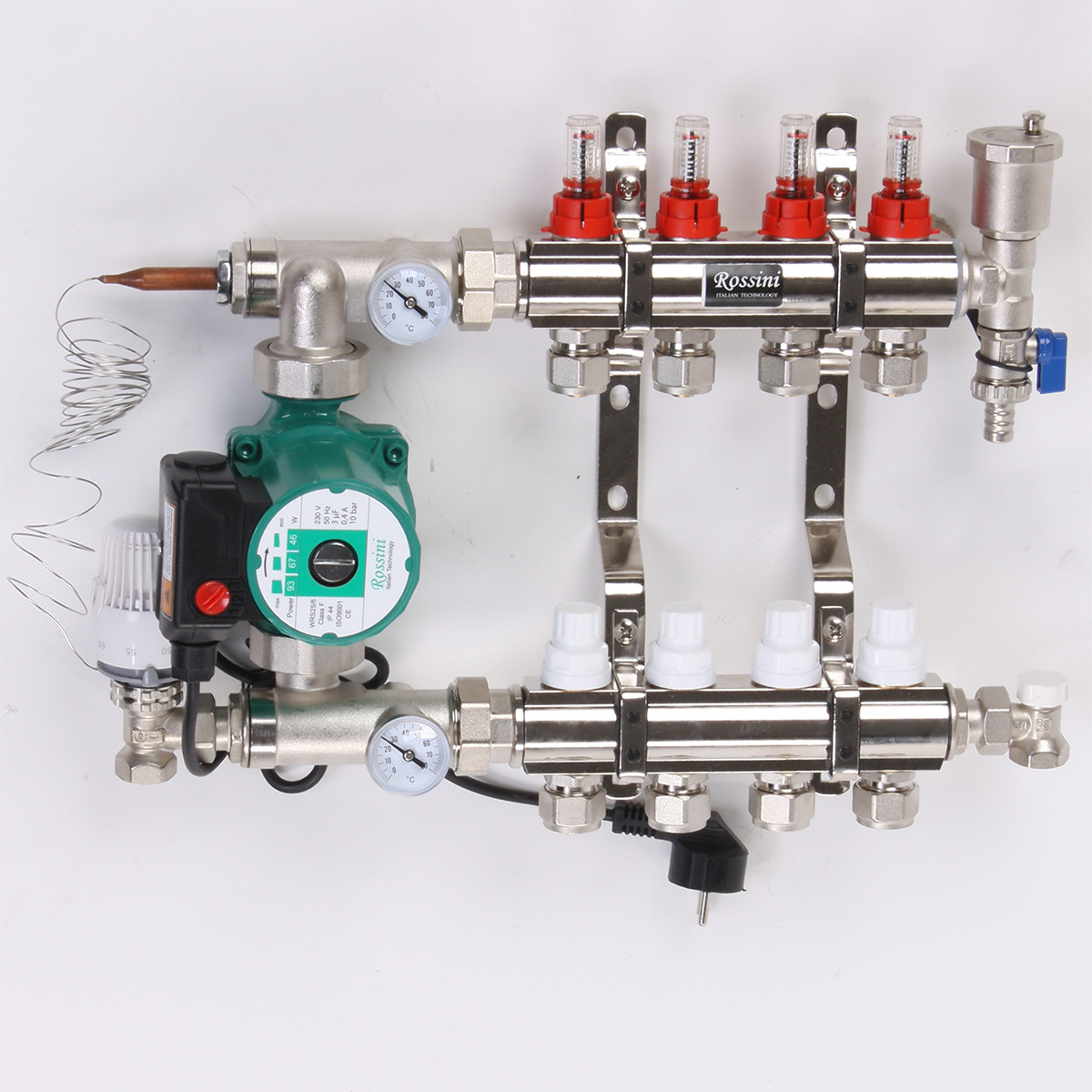
Heating manifolds are usually supplied by the manufacturer in assembled form, a standard-length circulation pump is installed later on an American-type threaded connection. Sometimes components are delivered to consumers separately, the assembly order consists of the following operations:
- Flow meters are installed on the supply comb and the end air outlet is screwed into the right end.
- A valve is connected to the return manifold with previously installed caps on the shut-off valves through an American on the right side.
- On both combs on the left, through the American, they install the drives for connecting the compression electric pump, while they are arranged in such a way that the fitting for installing the thermometer is on the front side.
- A tee is screwed into the return manifold, to which the thermostatic head is attached.
- Using a threaded connection (American) for mounting electric circulation pumps and gaskets from the kit, the pump is connected to the upper and lower combs.
- At the end of the work, pipes of standard diameter are connected to the collector block using the Eurocones included in the kit.
All main connections are sealed with rubber gaskets that come with the unit and the electric pump, sometimes there are no seals in the tap and tee of the supply comb, then linen tow or other plumbing materials are used for sealing
To carry out the work, one adjustable wrench is enough, while it is important not to pinch the nuts - this can lead to rupture of the gaskets
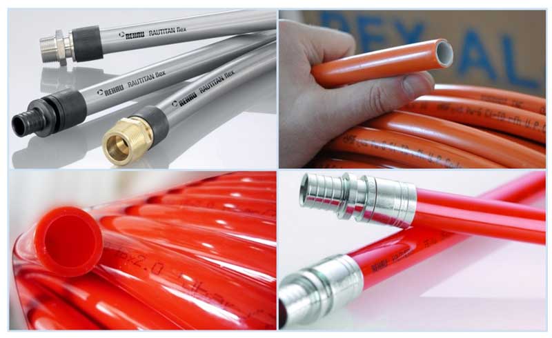
Rice. 18 PEX and PE-RT pipes
Collector-beam heating system
Collector in a beam-type heating system.
The heating collector should be considered together with the consideration of the radiant heat carrier wiring diagram, so it will be easier to understand its main functions and advantages.
As you know, there are three main types of piping.
- One-pipe scheme. Here, the radiators are connected in series, that is, the coolant is supplied to the first device, then passes through the battery and enters the next, gradually passing through the entire circuit and returning to the boiler. Obviously, after each radiator, the water cools down, and the heating of the batteries occurs unevenly;
- Two-pipe scheme. This solution provides for the supply of water through one pipe, and the outlet - through the second, that is, the circuit consists of two lines, between which radiators are connected in parallel. This scheme allows you to warm up the devices more evenly;
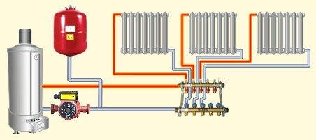
- Beam scheme. The coolant is supplied to the distribution unit (collector of the heating system), from where it goes to each radiator through a separate pipe, and then returns back through the return pipes, is collected by a comb and enters the boiler. Thus, it is possible to achieve the most even distribution of heat in the room.
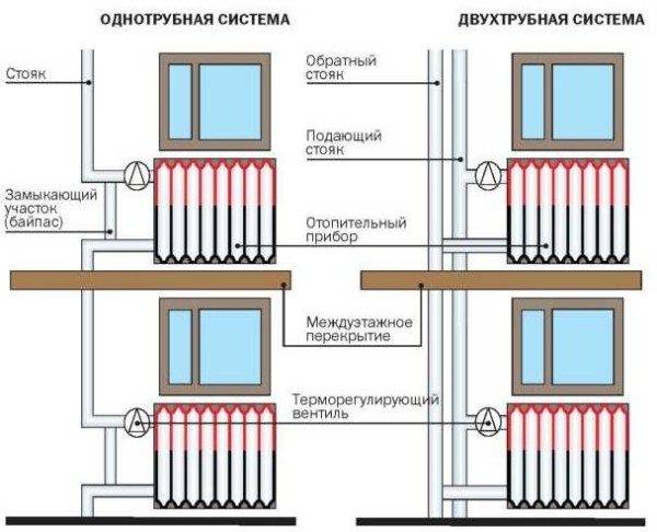
One-pipe and two-pipe schemes wiring.
Beam wiring diagram.
Important! As you can see, there are many circuits in the beam circuit, one for each battery. Therefore, for the normal operation of the system, a circulation pump is required, which can provide the necessary parameters for the pressure and circulation rate of the coolant. The beam scheme allows you to heat up each individual radiator as evenly as possible, moreover, it makes it possible to regulate the intensity of heat supply to each battery
The beam scheme allows you to warm up each individual radiator as evenly as possible, moreover, it makes it possible to regulate the intensity of heat supply to each battery.
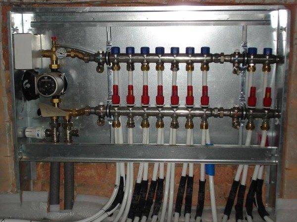
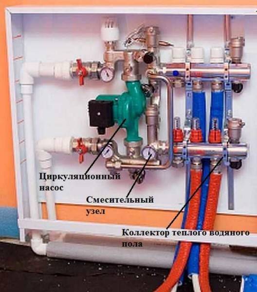
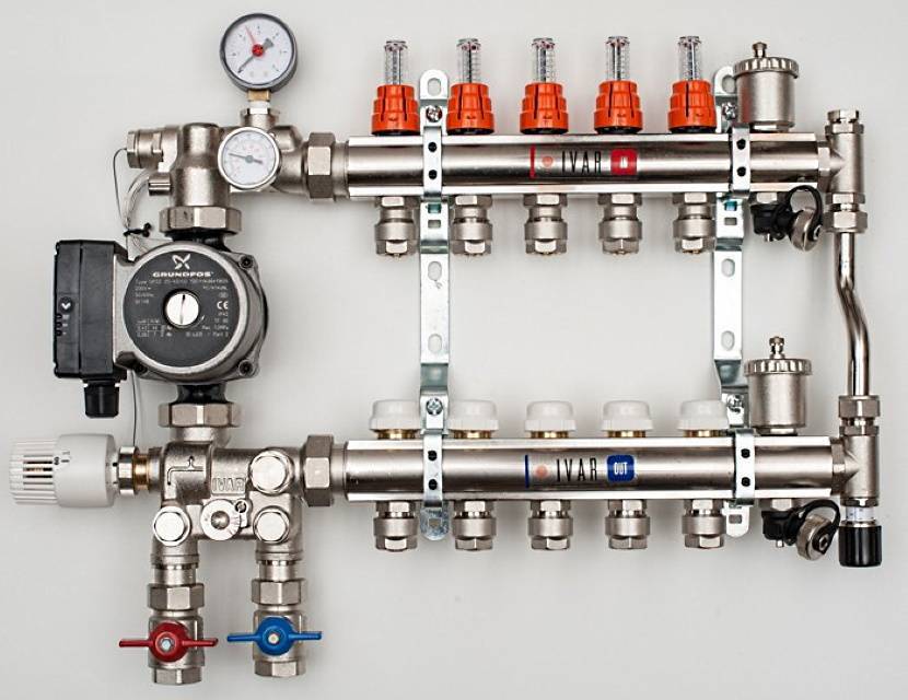
Manifold cabinet for radiator heating with supply and return combs.
Also, in such a scheme, you can turn off any device without changing the operation of the entire system, and in multi-storey buildings, you can turn off entire floors without interrupting the supply of coolant to other sections of the building.
To realize these advantages, heating collectors are used, which are included in the distribution unit in the form of a pair of devices - the supply and return combs. Tying the heating manifold with shutoff valves, air and drain valves, flow meters and thermostatic heads allows automatic control of temperature conditions on each individual heater.


The use of flow meters makes it possible to regulate the supply.
Important! Most often, such wiring is used in the construction of heating systems for private houses and cottages, however, this scheme can also be applied in an apartment with a centralized supply of coolant. It should be remembered that pipes are best carried out under the floor.Another advantage of beam wiring is the ability to hide the pipeline under the plinth or in the thickness of the floor.
Often it is this feature that influences the choice of wiring diagram.
Another advantage of beam wiring is the ability to hide the pipeline under the plinth or in the thickness of the floor. Often it is this feature that influences the choice of wiring diagram.
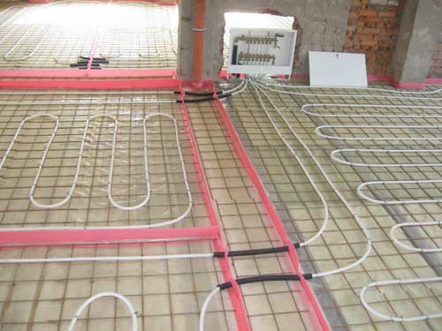
In the "warm floor" system, a collector for floor heating systems is necessarily used.
It is also impossible not to mention such a system as a "warm floor". Here, the circuits are not connected to radiators, but are laid in a special way in the floor screed in order to warm it up.
The only significant drawback of this solution is the high price of materials and work.
Criterias of choice
When choosing a heating distribution manifold for an underfloor heating system, you need to know in advance how many circuits you plan to connect. It is recommended to choose devices with a margin of one or two outputs in order to be able to adjust the system design and split the extended circuit into two branches or connect additional equipment (pressure gauge, thermometer). No more than nine loops can be connected to one collector, if there are more circuits, two or more distribution blocks are installed.

Maximum comb size
Next, you should pay attention to the material of manufacture of the comb. Reliable and durable cases are made of stainless steel, chrome-plated or nickel-plated brass, bronze
It is recommended to give preference to products manufactured in accordance with Russian GOSTs, or products of well-known manufacturers that have a certificate of conformity with European standards.Each comb should be carefully examined to identify possible flaws - cracks, corrosion, surface defects.
The list of reliable brands includes: Kermi, Valtec, Rehau, Valliant, Rossini, FIV. When buying branded products, it is advisable to take ready-made complete manifold blocks so as not to overpay for individual parts and avoid problems associated with incompatibility of elements from different manufacturers.
Video description
Popular types of collectors, the differences are shown in the video:
Assembly and installation
It is recommended to install a cabinet with a collector block in such a way that the underfloor heating loops are approximately the same length. If the distribution device is located above the level of the heating circuit, the air from the system will be automatically removed through the air vent. In the case when the cabinet is planned to be hidden in the basement or placed on the floor below, it will be necessary to install an air vent complete with a ball shut-off valve for each circuit, as well as on the return line.
When assembling the manifold block, pay attention to the tightness of the connections. If there are no sealing rubber rings in the kit with the equipment, the thread is sealed with winding. Next, the underfloor heating collector is installed in a special cabinet
The guides, equipped with bolts and nuts for fastening the combs, move in accordance with their length. If the manifold block is mounted without a cabinet, use clamps with dowels or brackets. At the same stage, if necessary, a mixing unit is mounted, a circulation pump for underfloor heating is installed. In conclusion, the circuits are connected, the system is pressure tested.


Next, the underfloor heating collector is installed in a special cabinet. The guides, equipped with bolts and nuts for fastening the combs, move in accordance with their length. If the manifold block is mounted without a cabinet, use clamps with dowels or brackets. At the same stage, if necessary, a mixing unit is mounted, a circulation pump for underfloor heating is installed. In conclusion, the circuits are connected, the system is pressure tested.
Video description
How the collector is installed, you will see the connection of the circuits in the video:
Briefly about the main
The equipment of the collector block must comply with the requirements for the functionality of the system. The collector device ensures uniform heating of the heating elements and a constant temperature in the room. It is made of the following materials: polypropylene, brass and steel.
The collector consists of a system to which threaded elements, fittings or control valves are connected. The collector is mounted in a special cabinet or brackets are used.
Along with it, a mixing unit is used.
The durability of the combs directly depends on the material and workmanship. You can purchase a ready-made complete distribution block or mount it yourself from individual elements.
Rules for installing a collector for underfloor heating
We offer a scheme, guided by which you can independently install the collector. However, there are a lot of them on the Internet. We place the one that clearly shows how to connect the most important parts of the system - pipeline, distribution unit and boiler.
Video installation instructions
We suggest that you familiarize yourself with the video instructions for installing a floor heating collector. We hope the video will help you install the underfloor heating collector yourself and learn more details about installing the device.
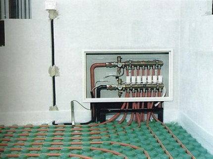
The collector cabinet is a small steel cabinet with a door, the parameters of which are 60 x 40 x 12 cm. And first you need to choose a place for its installation. If the wall thickness is sufficient, then a niche is made in the wall, into which the cabinet is placed. If the wall thickness does not allow, the manifold cabinet is mounted outside. The most successful place is the middle of the room, at the very surface of the flooring.
It is important that the surface of the wall is even and smooth. Otherwise, there may be interruptions in the operation of the system.
Why exactly at the surface? The fact is that the cabinet hides the system itself; in it, the heating pipes laid in the floor are docked with the supply and return pipes.
A shut-off valve is mounted on each pipe that departs from the collector and enters it. It limits the flow of liquid through the pipes or turns off the heating in the room altogether. The valve allows you to turn off the heating in one of the rooms, for example, in order to save or repair. This will in no way affect the comfort of the house, since in other rooms heating can occur in the same mode. The components are connected by fittings. The fixing of some solder joints occurs when using a template set: nut, sleeve and ring clamp. In the event that the diameter of the elements is different, adapters can be used.
- a collector is, simply put, a pipe sealed on both sides. There are several exits on the side of such a pipe (depending on the collector model). Pipes of the "warm floors" system are connected to them;
- comb adjustment begins with the removal of the protective cap from the valve. Close the valve completely with a hex wrench. Next, you need to determine the number of revolutions for a particular circuit. Turn the valve to this amount. Other circuits are configured in the same way;
- a drain cock is installed on the collector (provides drainage of water in case of damage to the system or repair work) and an air vent (automatically removes air and eliminates air congestion);
- in order to avoid hydrodynamic imbalance, thermostatic valves and flow meters are installed on the system.
How to do it yourself - a warm water floor
Earlier we talked about how to do it yourself installation of a water floor, what materials and tools are needed for this. See more about it here
Recommendations and advice
Before buying a collector, calculate the required length of pipes and their location. Experts recommend installing 2 to 6 flow meters instead of a manifold for 12 flow meters. This step will equalize the pressure and temperature in the most remote corners of the room.


After completing the installation of the collector cabinet and branches, you need to make a test run of the heating system. This will identify flaws and defects, as well as test the impermeability of the joints.
Brass models are more reliable and durable.
Buying a ready-made collector, and not its components, will help you save time and nerves.
The collector system has its pros and cons, and we cannot fail to mention them.
| Advantages | Flaws |
| Ease of use and management. So, being at one point in the house, you can adjust the flow and temperature of the coolant in another room | Price.The collector is often made of steel, and its cost is high |
| Aesthetics | It will take at least three hours to heat the room |
| Long service life (up to 50 years) | Each branch included in the control node can only feed one radiator, so the consumer buys pipes of small diameter |


