- Pro Tips
- Conclusion
- General wiring diagram of the switching device
- Schema creation
- How to calculate the number of places in the electrical panel
- Example of a simple calculation for a switchboard
- A few words about RCD
- Connection methods
- Comb
- Jumpers
- Model Z-ASA/230
- We get acquainted with the rules and prepare materials
- The main mistakes when connecting machines
- Connection of conductor ends without termination
- Insulation getting under the contact
- Conductors of different sections per terminal
- Soldering the ends of the lived
- The main errors of connecting difavtomatov
- Connection errors and how to avoid them
- Connection of machines in the shield - entrance from above or from below?
Pro Tips
Now it would be useful to turn to the advice of professional electricians, which will help to more competently disconnect the electrical panel and simplify its operation.
When installing a switchboard in an apartment or house, it is advisable to create a diagram of all connections with clear symbols. It can be drawn or printed on paper and glued on the inside of the shield housing door. This will allow, in the event of an emergency and the absence of the owner, almost anyone to quickly turn off or turn on the power.
For ease of maintenance and repair work, all wiring groups inside the switchboard are grouped according to the purpose of the lines. Grouping can be done with insulating tape or plastic clamps. Labels with appropriate inscriptions are attached to each group. When repairing wiring, you don’t have to puzzle over which wire is responsible for what and avoid unpleasant mistakes.
Once again, we remind you of the importance of the correct connection of circuit breakers - the input conductors are wound from above. For reliability, inspect the markings on the devices, most manufacturers place a correct connection diagram on them and the question - how to connect the machine in the shield, disappears by itself .. Exemplary shield
Model shield
After the test run, assembled or repaired switchboard, it is left open for several hours. In this case, it is desirable to increase the load on the network to the maximum. After a couple of hours, you can check if the components of the shield are heating up.
With proper assembly and calculations, there should be no elevated temperature. Otherwise, you need to turn off the shield and look for the source of the problem. If this is not done, a short circuit is inevitable.
Approximately once every six months it is necessary to tighten all the screws inside the switchboard
This is especially important when using aluminum wires in the network. Professionals recommend not to spare three places for installation in the modular socket shield
This will allow you to connect various tools and lighting to the shield, completely de-energizing all lines.
Professionals recommend not to spare three places for installation in the modular socket shield.This will allow you to connect various tools and lighting to the shield, completely de-energizing all lines.
To create a high-tech distribution panel, it is recommended to install a voltage relay in it. This device will monitor network performance and, in the event of a critical surge or voltage drop, will automatically turn off the load. After the restoration of the nominal values, it will turn on. Thus, it is possible to reliably protect electrical appliances with increased requirements for mains voltage.
Outdated machines - "traffic jams"
Once again, pay attention to the dimensions of the case, as mentioned above, it should be "for growth" providing the possibility of expanding the system. A more spacious housing reduces the mutual overheating of the elements and increases their service life.
The pulling of the contact fasteners can be combined with the cleaning inside the switchboard housing. Dirt makes the shield elements heat up more, and dust and cobwebs can become sources of short circuits.
Another example of the assembly of the shield in the video:
Conclusion
In conclusion, we can say that with due care, self-installation of a switchboard is a completely feasible measure. The main thing is not to forget about safety and make the right calculations. However, to ensure that mistakes are avoided, it is better to entrust this matter to professionals.
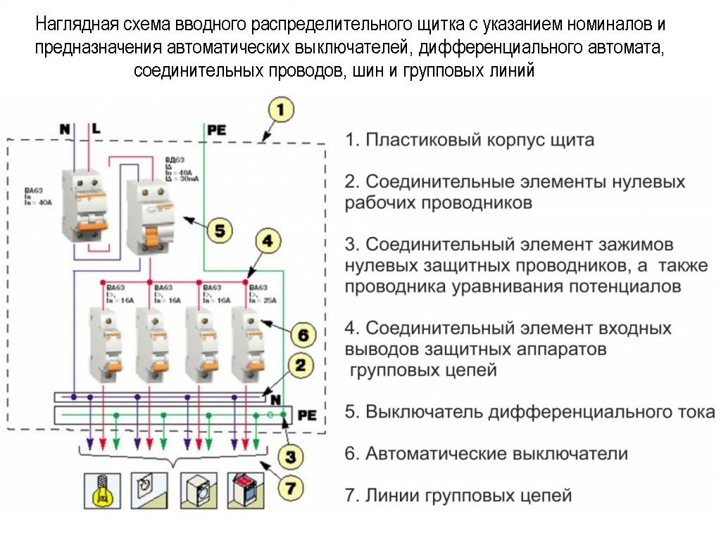
General wiring diagram of the switching device
Failure to follow the basic installation rules, even for such a simple device as a switch, can lead to very unpleasant consequences. Among which are overheating and sparking with a possible subsequent short circuit, as well as the voltage that is stored in the wiring.
This is fraught with electric shock even if you just need to replace the lamp with the lights off.
Therefore, before connecting the switch, it is worth remembering the main connection elements well:
Zero vein. Or, in electrician jargon, zero. It is displayed on the lighting device.
The phase assigned to the switch. In order for the lamp to go out and light up, the circuit must be closed within the phase core


It is important to remember that when the switching device is brought to zero in the opposite direction, it will work, but the voltage will remain. Therefore, to replace the lamp, for example, you will have to disconnect the room from the power supply.
Phase assigned to the lamp
When you press the key, the circuit will close or open at the point of breaking the phase channel. This is the name of the section where the phase wire ends, leading to the switch, and the segment stretched to the light bulb begins. Thus, only one wire is connected to the switch, and two to the lamp.
It should be remembered that any connections of conductive sections must be carried out in a junction box. It is highly undesirable to perform them in a wall or in plastic channels, since complications will certainly arise with the identification and subsequent repair of damaged fragments.
If there is no junction box near the installation site of the switch, you can extend zero and phase from the input shield.
The figure shows the connection diagram of a single-gang switch. Wire junctions are marked with black dots (+)
All the above rules apply to a single-gang switch.They also apply to multi-key devices with the difference that a fragment of a phase wire from the lamp that it will control is connected to each key.
The phase stretched from the junction box to the switch will always be only one. This statement is also true for multi-key devices.
Replacing the switch or installing it from scratch is carried out only if there is a fully formed electrically conductive circuit.
In order not to make a mistake when working with wiring, you need to know the marking and color of current-carrying channels:
- The brown or white color of the wire insulation indicates the phase conductor.
- Blue - zero vein.
- Green or yellow - grounding.
Installation and further connection is made according to these color prompts. In addition, the manufacturer can apply special markings to the wires. All connection points are denoted by the letter L and a number.
For example, on a two-gang switch, the phase input is designated as L3. On the opposite side are the lamp connection points, referred to as L1 and L2. Each of them will need to be brought to one of the lighting fixtures.
Before installation, the overhead switch is disassembled, and after connecting the wires, the housing is mounted back
Schema creation
An electrical panel in a private house or apartment begins with design work, namely, the creation of a wiring diagram. At the same time, it is desirable to adhere to a rational approach to the distribution of future elements. This will not only make the device more compact, but also save on wiring. At this stage, the place for the installation of the finished equipment is finally determined.
How to calculate the number of places in the electrical panel
A rational approach to the design of a switchboard, first of all, implies a competent calculation of the number of meters for the installed equipment. In practice, this is not difficult, since all modern components of electrical panels have strictly unified dimensions.
One module is considered here as a unit of measurement. This area is equal to the space occupied by a circuit breaker with one pole. Its width is 17 and a half centimeters. This standard is international and is suitable for any modern electrical components.
For ease of calculation, we offer you a table with the main components that may be required in the switchboard.
Module size table:
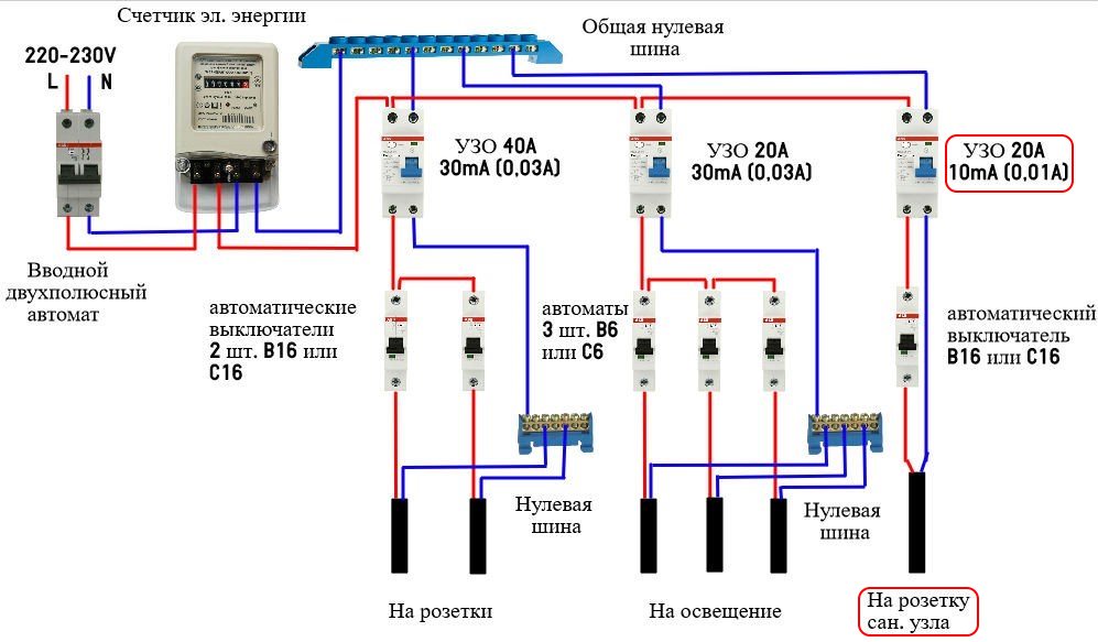
Example of a simple calculation for a switchboard
For a practical understanding of how such calculations are carried out, let's give a small example for a simple distribution panel in an apartment or a private house.
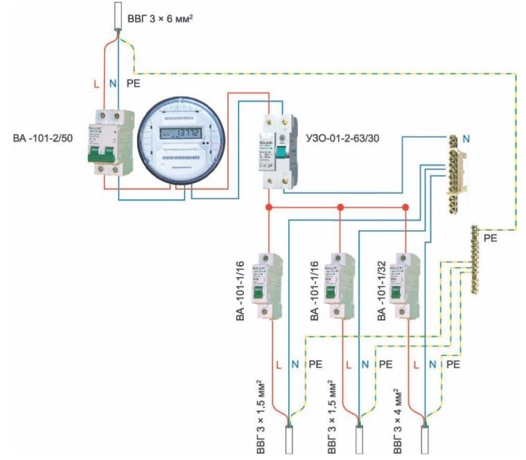
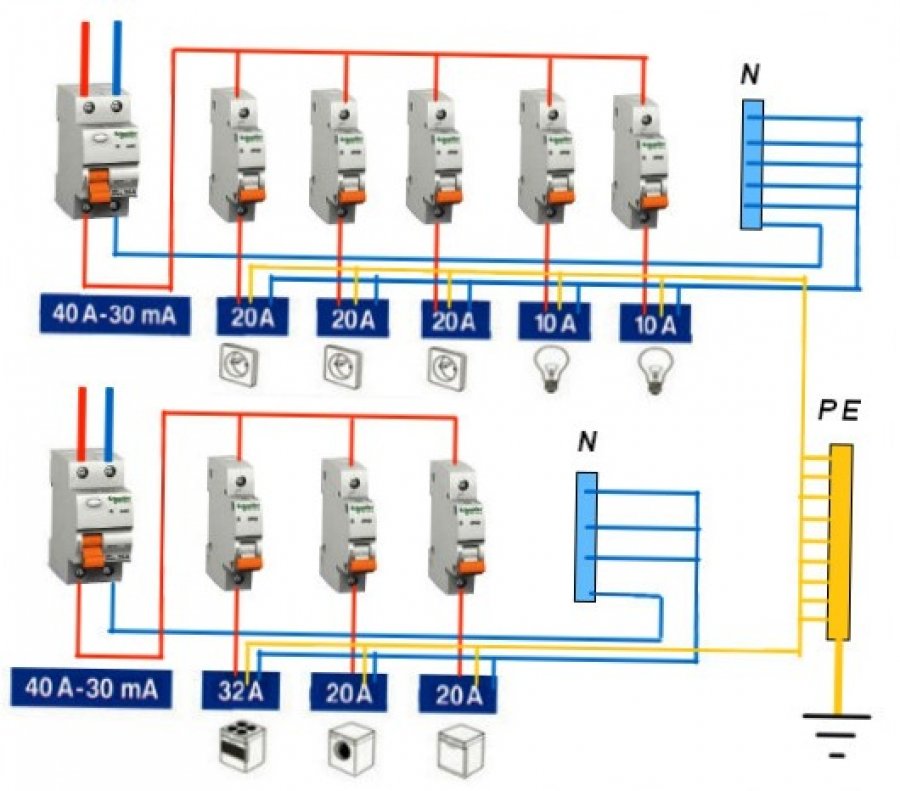
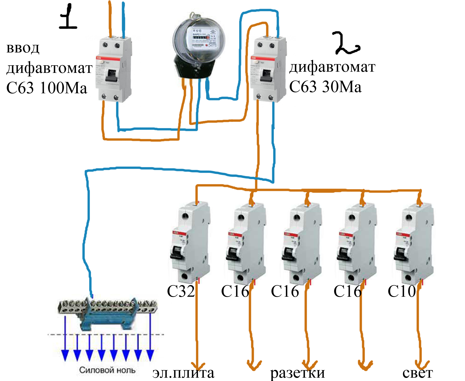
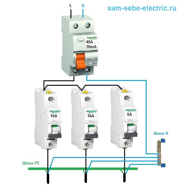
The figure shows a circuit in which an electric energy meter is included. According to the conditions of our task, the input of the main line was made using a VVGng cable with a cross section of 3 * 6 square millimeters. Now let's count the modules installed in the shield and the space they occupy:
- upstream 2-pole circuit breaker = 2 modules;
- further installed electricity meter = 6 modules;
- after the counter, two RCDs = 4 modules;
- circuit breakers with one pole in the amount of six pieces = 6;
- zero tires designed for two RCDs = 2.
Let's summarize by summing up all the modules and get - 20 places and this is for the simplest distribution board. Since all experts recommend including a certain reserve in the calculations, in case additional components are installed, we understand that the enclosure for the shield must be purchased for at least 24 places. It is advisable to increase this value to 40, so as not to encounter the problem of lack of space later.
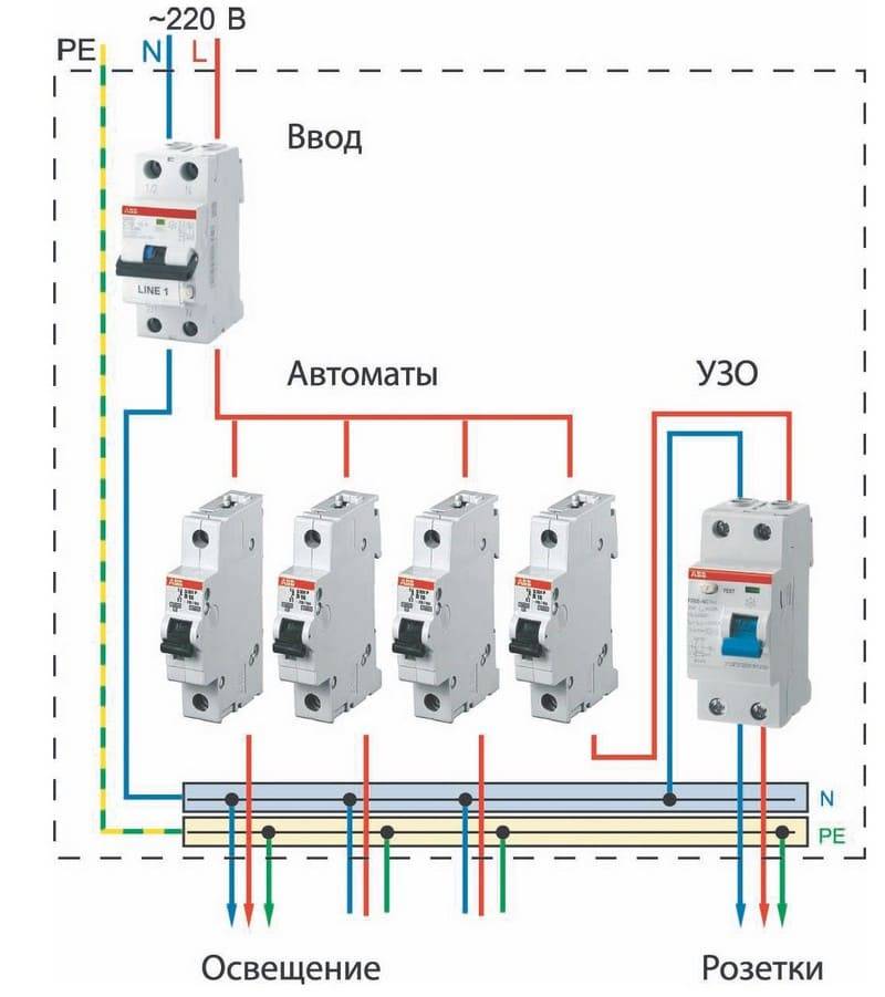
Scheme of a small distribution board
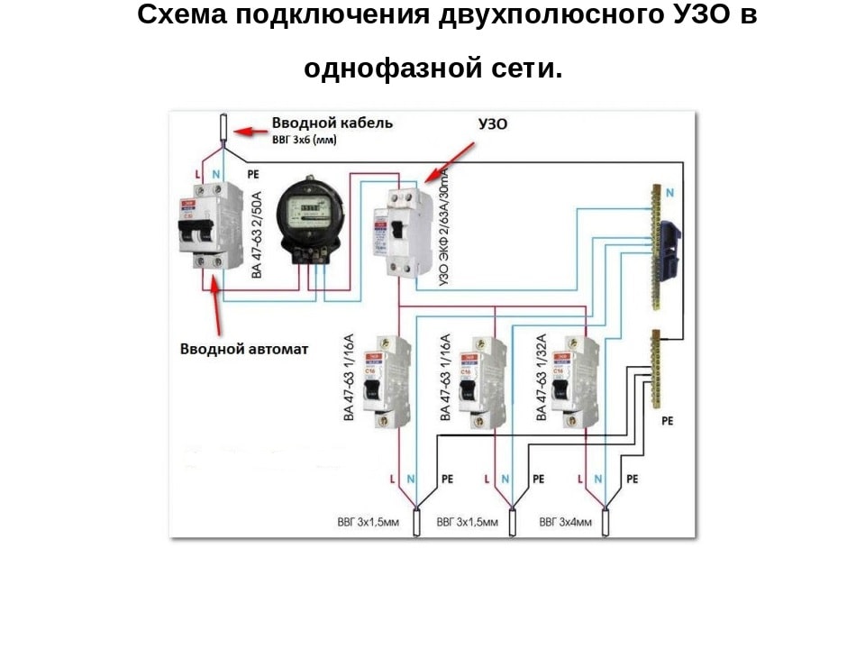
A few words about RCD
When designing and installing, it is important to remember one more thing - the inclusion of an RCD in the circuit. This abbreviation stands for Residual Current Device.
Like the RCD machine, it is a protection device, but much more sensitive.
Automatic switches are calculated on work with short circuits in a network. The current at such loads can reach hundreds of amperes. However, even a couple of tens of milliamps can adversely affect human health. RCDs protect against such troubles.


For example, a child put a foreign object into the socket, and the current will be instantly turned off. Plus, you need to add the type of grounding in the apartment. A system with three phases and zero is already widely used (international standard TN-C). RCD in such a system is the only and reliable protection against overloads.
Connection methods
Comb
For convenient and high-quality connection of circuit breakers in the shield, you can use a bus. Depending on the number of phases, you can choose the desired comb:
- for a single-phase circuit - single-pole or two-pole;
- for three-phase - three- or four-pole.
Installation is very simple.Under the required number of circuit breakers, a comb with a certain number of poles is selected. If the comb has a larger number of contacts, the excess is removed (you can use a hacksaw). Finishing the installation, insert the tire simultaneously into all the clamps of the machines and tighten the screws. Outputs are mounted according to the scheme. More details about that, we talked about in the corresponding article. The video below clearly demonstrates the connection technology:
Jumpers
This type of connection is used if there are few machines and there is enough space in the shield for free access to contacts. This method can be applied to both single-phase and three-phase circuits.
To perform work in the shield, it is necessary to prepare jumpers of suitable length and section. The cross section of single-core conductors for connecting circuit breakers must be sufficient for the calculated power consumption. About that, we talked about in the corresponding article.
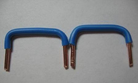
The ideal option would be to make jumpers in an unbreakable way:
From one piece of the conductor, bending it with pliers, make a jumper that will connect all the circuit breakers. The wire must be bent with the required distance. After such preparation, remove the insulation from the ends by about 1 cm, strip the wire by removing the oxide film with a knife or sandpaper.
It is important to remember that in this case, the phase and neutral wires should not be tightly pressed against each other. This is due to the fact that during the operation of the electrical network they heat up, and an undesirable connection of the phase and zero may occur due to the insulation softened by heating.
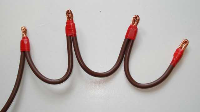
To connect the machines in the shield with a loop, you can also use a stranded wire of the desired section. But in this case, it must be stripped of insulation by 1-1.5 cm. At the end of the wire, you need to put on a tip that matches the cross section of the wire in diameter, and crimp it with special tongs. Serial connection of several machines is allowed.

In the absence of the proper tool and lugs, it is permissible to pierce the wire exposed from the insulation with a soldering iron. Tin or solder falls between the strands of a stranded conductor, forming a fairly strong connection of thin strands. And, although this method is considered less reliable than the previous one, it is often used due to its ease of use.
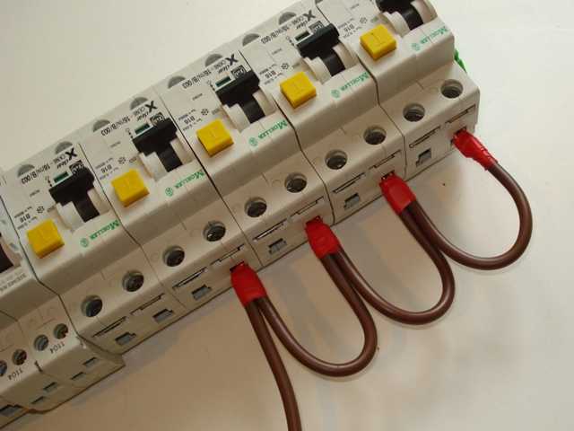
In the absence of a soldering iron, installation can also be carried out with the help of conductors that have the insulation removed at the ends, clamping them directly into the machine. This type of installation is the least reliable and, under heavy loads, threatens to heat the conductors at the junction and, accordingly, increase the fire hazard. This type of connection has a not very aesthetic appearance and low reliability.
Do-it-yourself connection of automata in the shield using a stranded insulated conductor must be carried out in compliance with the previously drawn up scheme. Circuit breakers in this case, you can not necessarily use one manufacturer. Their dimensions may vary, because flexible wire installation allows this.
Conducting permissible electric current and cutting off power when exceeding the rating. It serves to protect electrical circuits from overloads. A single-pole circuit breaker provides protection for only one wire.
Model Z-ASA/230
Switching off ventilation in case of fire via the shunt release Z-ASA/230 is very fast. This model is made with movable plates. There are six pairs of contacts in total. For impulse switches, this device is ideal
It is also important to note that the model is able to operate in conditions of high humidity. The actual opening of the contacts is carried out very quickly. For remote control of the ventilation system, this setting is well suited.
The current conductivity of the presented release is 4.5 microns
For remote control of the ventilation system, this setting is well suited. The current conductivity of the presented release is 4.5 microns.


In this case, the output voltage on the relay is 30 V. The stabilizer in the device is installed without an adapter. Transistors are of dual type. The model does not have a kenotron. The independent release is connected to the shield through a dinistor. It is installed with one panel, which is located at the bottom of the case. Before connecting the device, first of all, the negative resistance is checked for each phase
It is also important to note that it is important to carefully insulate the wiring.
We get acquainted with the rules and prepare materials
First of all, everyone, and especially beginners, need to remember the basic safety rules when manipulating electricity:
- Always turn off the electricity and make sure with a multimeter or an indicator screwdriver that it is absent directly at the work site.
- Do not touch bare veins with your hands.
- Examine the color and other markings of wires, carefully ensure that the neutral wire is connected to zero, ground to ground, and phase to phase. Otherwise, a short circuit is possible up to the ignition of the wiring.
- Choose high-quality electrical components and consumables, do not reuse old switches and wires.
- To connect the wires, use soldering, terminals, connecting blocks, and not twisting and insulating tape.
- Calculate the maximum voltage on the wires and, in connection with this parameter, choose the cross-sectional diameter and other performance characteristics of the conductor.
- Familiarize yourself with the installation diagram of the switch of the selected type (with one, two or three keys).

It is also necessary to prepare in advance all the necessary tools and materials. So, to install the electrical wiring of the switch, you will need a drill or a puncher, a special nozzle for making a hole, a multimeter, screwdrivers (including an indicator), a spatula, pliers, a knife, a two-wire wire, a socket box, a switch, putty or gypsum mortar.


The main mistakes when connecting machines
- Let's analyze the errors that are most common:
- connection of the ends of the conductors of a flexible stranded wire without termination;
- insulation getting under the contact;
- connection of conductors of different sections to one terminal;
- soldering the ends lived.
Connection of conductor ends without termination
The main mistake when connecting machines is the use of a flexible stranded wire without termination. It's easier and faster, but not right. Such a wire cannot be clamped securely; over time, the contact weakens (“flows”), the resistance increases, the junction heats up.
It is necessary to use lugs on a flexible wire or use a rigid single-core wire for installation.
Insulation getting under the contact
Everyone knows that before connecting the machine in the shield, you need to remove the insulation from the connected wires. It would seem that there is nothing complicated here, I stripped the core to the desired length, then insert it into the clamping terminal of the machine and tighten it with a screw, thereby ensuring reliable contact.
But there are cases when people are at a loss as to why the machine burns out when everything is connected correctly. Or why the power in the apartment periodically disappears when the wiring and filling in the shield are completely new.
One of the reasons for the above described is the penetration of the wire insulation under the contact clamp of the circuit breaker. Such a danger in the form of poor contact carries the threat of melting the insulation, not only the wire, but also the machine itself, which can lead to a fire.
To exclude this, you need to monitor and check how the wire is tightened in the socket. The correct connection of the machines in the switchboard should exclude such errors.
Conductors of different sections per terminal
Never connect circuit breakers with jumper cables of different sections. When the contact is tightened, a core with a large cross section will be well clamped, and the one with a smaller cross section will have poor contact. As a result, the insulation is melted not only on the wire, but also on the machine itself, which will undoubtedly lead to a fire.
- An example of connecting circuit breakers with jumpers from different cable sections:
- The “phase” comes to the first machine with a 4 mm2 wire,
- and other machines already have jumpers with a 2.5 mm2 wire.
As a result, poor contact, temperature increase, insulation melting not only on the wires, but also on the machine itself.
For example, let's try to tighten two wires with a cross section of 2.5 mm2 and 1.5 mm2 in the circuit breaker terminal. No matter how hard I tried to ensure reliable contact in this case, nothing worked out for me. A wire with a cross section of 1.5 mm2 dangled freely and sparked.
Soldering the ends of the lived
Separately, I would like to dwell on such a method of terminating the wires in the shield as soldering. This is how human nature works, that people try to save on everything and do not always want to spend money on all kinds of tips, tools and all modern small things for installation.


For example, consider the case when an electrician from the ZhEK, Uncle Petya, wires an electrical panel with a stranded wire (or connects outgoing lines to an apartment). He does not have NShVI tips. But there is always a good old soldering iron at hand.
And the electrician Uncle Petya finds no other way out than to irradiate the stranded core, stuffs the whole thing into the terminal of the machine and tightens it with a screw from the heart. What is the danger of such a connection of machines in the switchboard?
When assembling switchboards, DO NOT solder and tin the stranded core. The fact is that the tinned compound begins to “float” over time. And in order for such a contact to be reliable, it constantly needs to be checked and tightened. And as practice shows, this is always forgotten.
The soldering begins to overheat, the solder melts, the junction weakens even more and the contact begins to “burn out”. In general, such a connection may result in a FIRE.
The main errors of connecting difavtomatov
Sometimes, after connecting the difavtomat, it does not turn on or is cut down when any load is connected. This means that something is done wrong. There are several typical mistakes that occur when assembling the shield yourself:
- The wires of the protective zero (ground) and the working zero (neutral) are combined somewhere. With such an error, the difavtomat does not turn on at all - the levers are not fixed in the upper position. We'll have to look for where the "ground" and "zero" are combined or confused.
- Sometimes, when connecting a difavtomat, zero to the load or to the below located automata is taken not from the output of the device, but directly from the zero bus. In this case, the switches become in working position, but when you try to connect the load, they instantly turn off.
- From the output of the difavtomat, zero is not fed to the load, but goes back to the bus. Zero for the load is also taken from the bus. In this case, the switches become in working position, but the "Test" button does not work and when you try to turn on the load, a shutdown occurs.
- Zero connection mixed up. From the zero bus, the wire must go to the appropriate input, marked with the letter N, which is at the top, not down. From the bottom zero terminal, the wire should go to the load. The symptoms are similar: the switches turn on, the "Test" does not work, when the load is connected, it trips.
- If there are two difavtomatov in the circuit, the neutral wires are mixed up. With such an error, both devices turn on, "Test" works on both devices, but when any load is turned on, it immediately knocks out both machines.
- In the presence of two difautomats, the zeros coming from them were connected somewhere further. In this case, both machines are cocked, but when you press the "test" button of one of them, two devices are cut down at once.A similar situation occurs when any load is turned on.
Now you can not only choose connect differential machine protection, but also to understand why he knocks out, what exactly went wrong and correct the situation on his own.
Connection errors and how to avoid them
When installing switchgears, novice, and often experienced electricians, often make mistakes that can subsequently lead to a fire or at least a power outage. The most common of them:
Stripper
- insulation getting under the terminal. In this case, it turns out that the contact is weakly clamped. At the junction, the contact resistance increases, the contact begins to overheat;
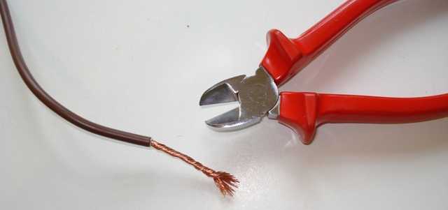
- stripping wires with side cutters or pliers. These are wrong, because with this method of removing the insulation, a small transverse incision is formed on the conductor, and the core can break off at the point of damage. For cleaning, you need to use a specialized tool - a stripper or at least a knife. With a knife, the insulation is removed as if they were stripping a pencil. With this method, incisions are not formed;
- stranded wire installation. When tightening the terminal, the cores diverge to the sides. The connection turns out to be loose, and since part of the wires does not fall under the contact, the cross section of the wire at the attachment point decreases. The cores of the stranded wire must be terminated with special lugs that are produced for each section. The ends are crimped with pliers or a special tool - a crimper;
- tinning of stranded wires.Often there is an opinion that instead of mounting the lugs, you can irradiate and solder the strands of the stranded wire. Solder is softer than copper and tends to melt under pressure. As a result, contact deteriorates after a while;
- installation under one terminal of wires of different sections. Since the terminals are rigid, only a wire with a large cross section can be reliably connected. Thinner ones won't pinch. To connect several machines, a special comb bus is used. If there is no such bus, then take a piece of wire of the desired section. A jumper of the required shape is formed and only then the insulation is removed at the clamping points.
Crimper
Note! Errors in the order of connection of protection devices are less critical. It is considered correct to enter into automatic machines or RCDs in the same way throughout the structure. Input should be placed at the top
In this case, the safety of the switchboard maintenance is significantly increased.
Input must be placed at the top. In this case, the safety of servicing the switchboard is significantly increased.
Incorrect choice of automation or poor-quality installation of distribution equipment not only reduces safety, but can also cause questions for regulatory organizations. It is better to entrust the work to professional electricians.
Connection of machines in the shield - entrance from above or from below?
The first thing I would like to start with is the correct connection of the machine in principle. As you know, the circuit breaker has two contacts for connecting a movable and a fixed one. On which of the pins you need to connect power to the top or bottom? To date, there has been a lot of controversy about this.There are a lot of questions and opinions on this subject on any electrical forum.
Let's turn to the regulations for advice. What does the PUE say about this? In the 7th edition of the PUE, clause 3.1.6. says:
As you can see, the rules say that when connecting the machines in the shield, the supply wire should, as a rule, be connected to fixed contacts. This also applies to all ouzo, difavtomat and other protection devices. From all this clipping, the expression "as a rule" is not clear. That is, it seems, as it should, but in some cases there may be an exception.
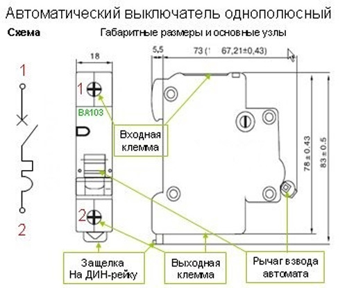
To understand where the moving and fixed contact is located, you need to imagine the internal structure of the circuit breaker. Let's use the example of a single-pole machine to consider where the fixed contact is located.
Before us is an automatic machine of the BA47-29 series from iek. It is clear from the photo that the upper terminal is the fixed contact, and the lower terminal is the movable contact. If we consider the electrical designations on the switch itself, then here it is also clear that the fixed contact is on top.


Circuit breakers from other manufacturers have similar designations on the case. Take, for example, a machine from Schneider Electric Easy9, it also has a fixed contact on top. For Schneider Electric RCDs, everything is similarly fixed contacts on top and movable contacts on the bottom.
Another example is Hager safety devices. On the case of circuit breakers and RCD hager, you can also see the designations, from which it is clear that the fixed contacts are on top.
Let's see if it matters from the technical side, how to connect the machine from above or below.
The circuit breaker protects the line from overloads and short circuits. When overcurrents appear, the thermal and electromagnetic releases located inside the housing react. From which side the power will be connected from above or below for the tripping of the releases, there is absolutely no difference. That is, we can say with confidence that the operation of the machine is not affected by which contact the power will be supplied to.
In truth, I must say that manufacturers of modern "brand" modular devices, such as ABB, Hager and others, allow power to be connected to the lower terminals. For this, the machines have special clamps designed for comb tires.
Why, then, in the PUE, is it advised to connect to fixed contacts (upper)? This rule is approved for general purposes. Any educated electrician knows that when performing work, it is necessary to remove voltage from the equipment on which he will work. "Climbing" into the shield, a person intuitively assumes the presence of a phase from above on the machines. By turning off the AB in the shield, he knows that there is no voltage at the lower terminals and everything that comes from them.
Now imagine that the connection of the automata in the switchboard was performed by the electrician Uncle Vasya, who connected the phase to the lower AB contacts. Some time has passed (a week, a month, a year) and you need to replace one of the machines (or add a new one). The electrician Uncle Petya comes, turns off the necessary machines and confidently climbs with his bare hands under voltage.
In the recent Soviet past, all machine guns had a fixed contact at the top (for example, AP-50). Now, according to the design of modular ABs, you cannot tell where is the movable and where is the fixed contact.In the ABs that we considered above, the fixed contact was located on top. And where are the guarantees that the Chinese automatic machines will have a fixed contact located on top.
| Therefore, in the rules of the PUE, connecting a supply conductor to fixed contacts implies only connecting to the upper terminals for the purposes of general order and aesthetics. I myself am a supporter of connecting power to the top contacts of the circuit breaker. |
For those who do not agree with me, the question of backfilling is why, in electrical circuits, the power to the machines is connected precisely to the fixed contacts.
If we take, for example, a conventional RB type switch, which is installed at every industrial facility, then it will never be connected upside down. The connection of power to switching devices of this kind assumes only the upper contacts. Turned off the breaker and you know that the lower contacts are without voltage.


