- Refinement of typical devices
- Instructions for assembling a touch switch on transistors and relays
- Design features and principle of operation
- Types of touch switches
- capacitive
- Opto-acoustic switches
- With remote control
- With timer
- Circuit elements
- Device Options and Capabilities
- What does the market offer?
- Introduction to Ribbons
- Advantages
- Some features of branded switches
- Setting up the remote control
- Connecting a single-key touch switch Livolo VL-C701R
- The relationship of mechanisms
- Circuit Assembly
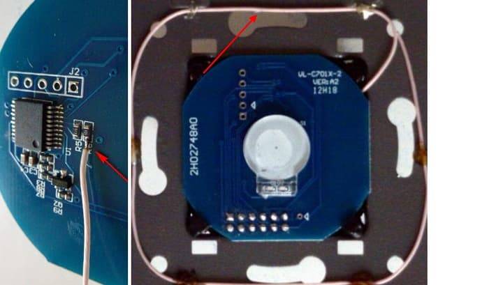
Refinement of typical devices
Many people are not satisfied that the touch zone on the panel is rather small, and to fix the signal, you need to touch in the indicated place. Let us give an example of how it is possible to increase the area of indirect surface contact.
 Increasing the sensor sensitivity zone
You should take the wire and carefully solder it to the place where the signal is supplied from the sensor on the sensor board (for this you need to study the circuit diagram of the device). The connected wire is laid around the perimeter of the case. As a result, such a frame will allow, without amplifying the signal level, to trigger the sensor when the front panel is touched.
It should be noted that such an improvement will void the manufacturer's warranty.
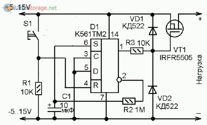
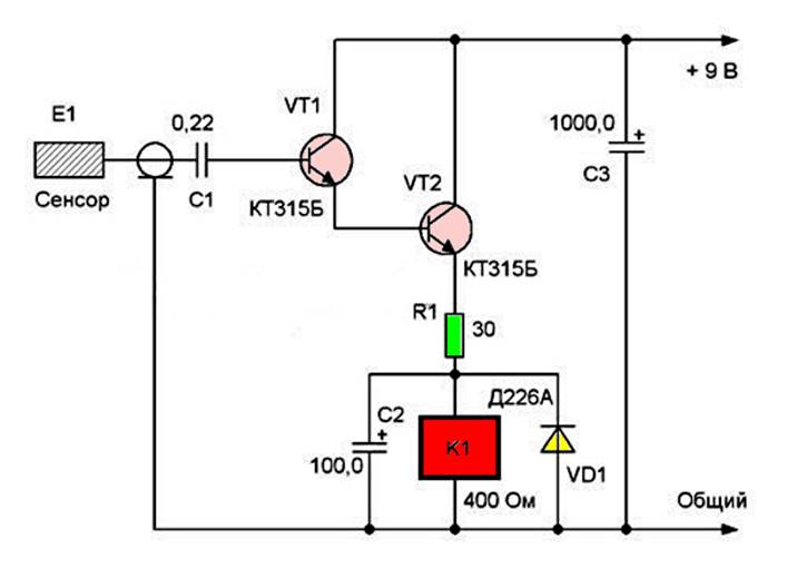
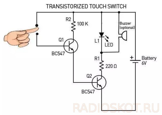
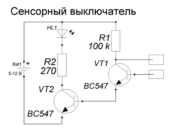
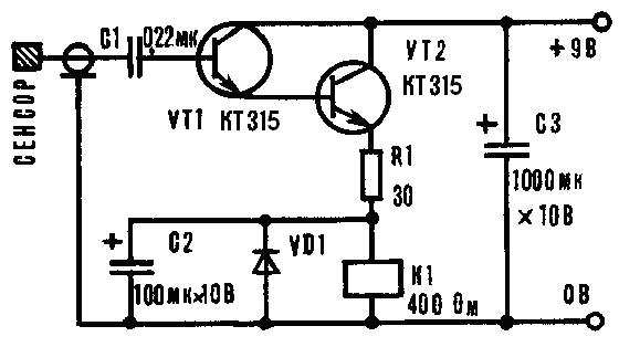
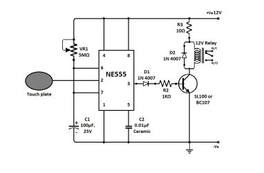
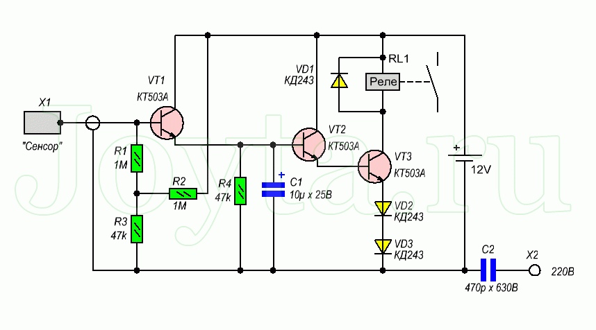
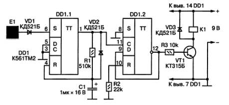
Instructions for assembling a touch switch on transistors and relays
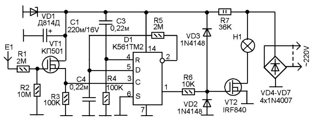
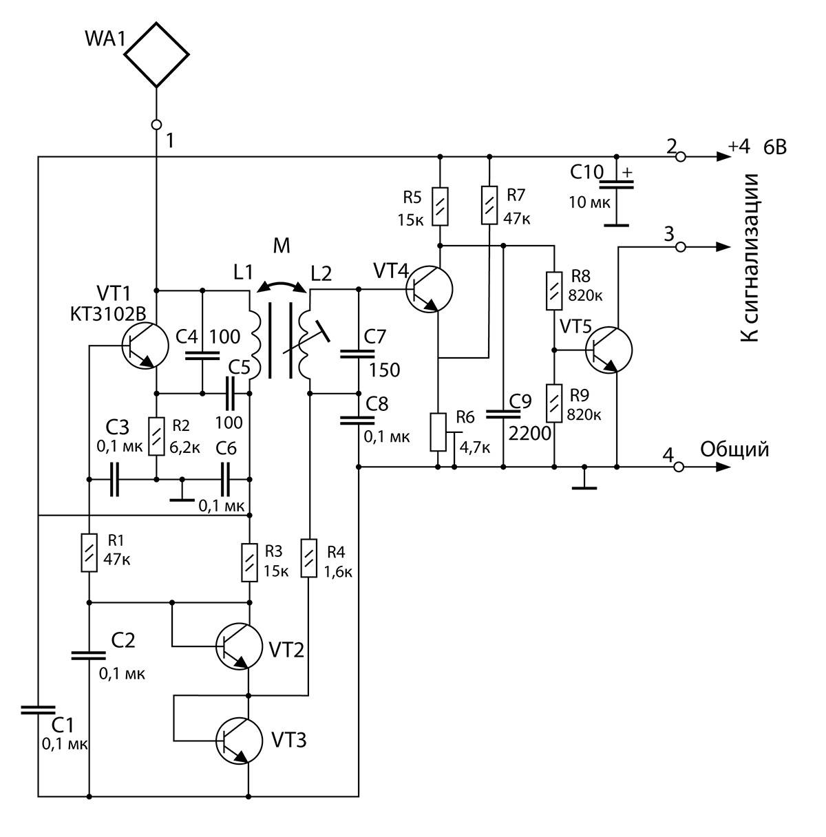
One of the simplest 220V touch switches for do-it-yourself manufacturing is considered to be a circuit using a relay. At the heart of it is a simple amplifier, on two transistors VT1 and VT2 of the KT315B series, a signal from an inductive sensor passing through an isolation capacitor C1. Depending on the state of the K1 relay itself, either a voltage supply interruption to it occurs, or power is restored.
For the device, it is necessary to provide for the supply of a constant voltage of 9V to the board, through an external power supply or an additional step-down circuit using a diode bridge and a transformer.
Touch switch using relay
Design features and principle of operation
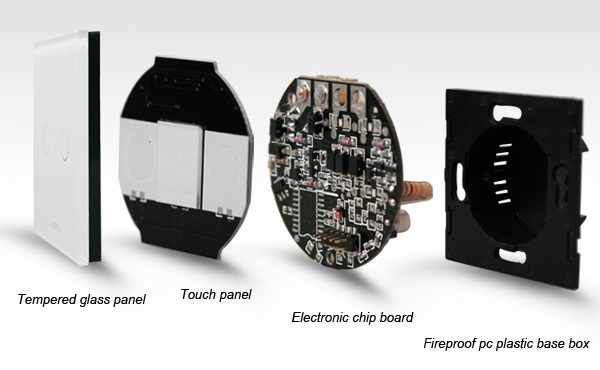
The touch switch works even when the button is weakly touched. Consists of three main elements:
- control block. The system processes the external signal and transmits it to the necessary parts.
- Switching device. load Gives an electrical network that closes and opens and changes the circuit current strength to the lamp.
- Touch (panel) control. It is intended for perception of touches of signals or from the remote control. In modern sensors, you can not touch the devices, just hold your hand nearby.
Standard models of switches are endowed with the following features:
- Turn on / off the light, regulate Control.
- brightness of the operation of heating equipment and report temperature changes.
- Open/close blinds.
- Turn on / turn off household appliances connected to the switch.
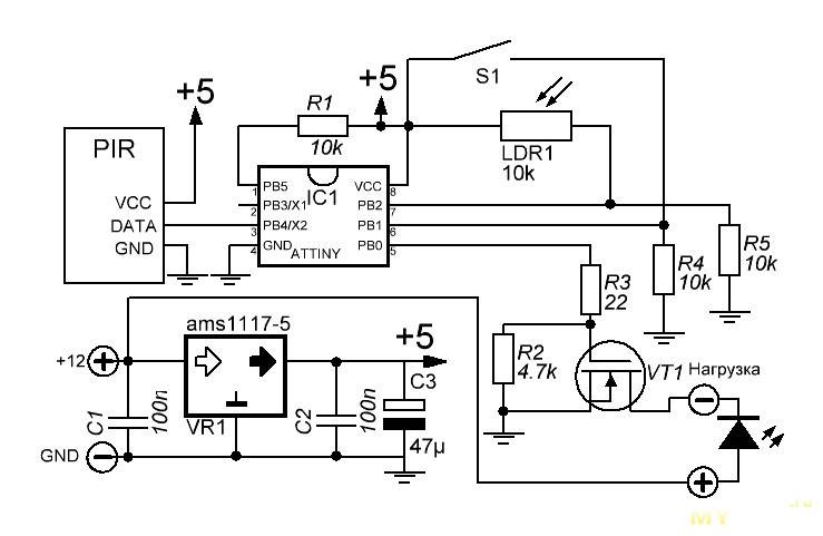
Of the additional features, a motion sensor is very useful.
Types of touch switches
Touch switches are of several types:
- capacitive;
- optical-acoustic;
- with control panel;
- with a timer.
To make the right choice for your needs, consider each type in more detail.
capacitive
Popular type of switch. The touch sensor is very sensitive, it is triggered when people approach, when the hand is brought to the touch surface or held next to it. Such a switch will be relevant in the kitchen, because you do not need to touch it for it to work.
These switches are stylish and easy to use. They are easier to care for than conventional pushbutton switches.
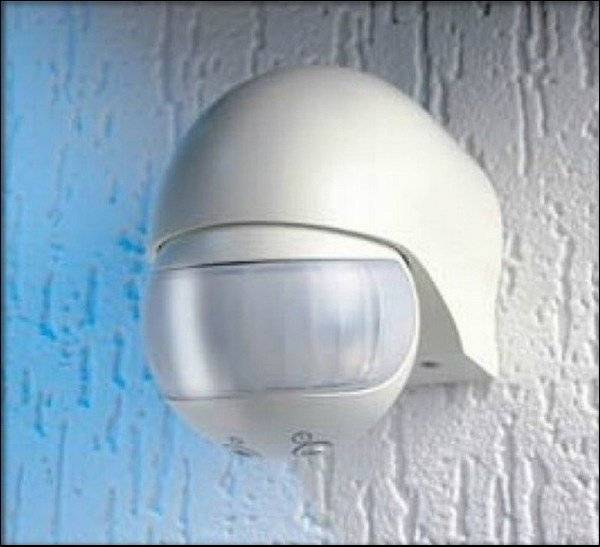
Opto-acoustic switches
These switches respond to sound or movement within the sensor's range. When no one is in the room, the light turns off. They allow you to save energy. In apartments, such switches are rarely used. They are more often placed in common areas to illuminate rooms or open doors that "feel" the visitor's approach.


With remote control
Switches with a remote control are especially convenient in a home where children or people with disabilities live. Useful if the switch is located inconveniently or it is difficult for children to reach it. And they also give comfort when there is no desire to get out of bed to turn off the light or appliance, lower the curtains.
With timer
The timer allows you to turn on and off the device or light in a certain mode. Timer switches are universal. They are easy to use, work with any type of lamp: LED, halogen or incandescent.
Their advantage is safety. If a short circuit occurs, the circuit breaker will automatically switch to the off position.
The switches are equipped with indicators that show whether it is currently on.And users also note ease of installation, ease of use, attractive appearance, reliability.
A switch with a timer is suitable if you want to regulate the time of its operation. This can be handy when you need to program an electrical appliance to turn on or off. These switches help you save energy.
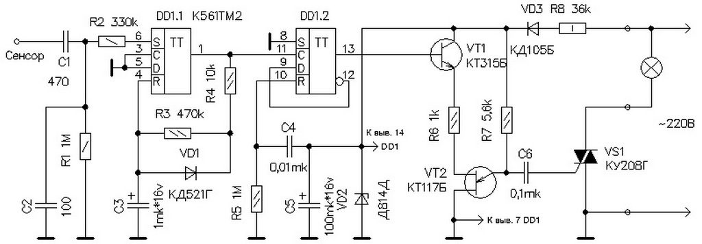
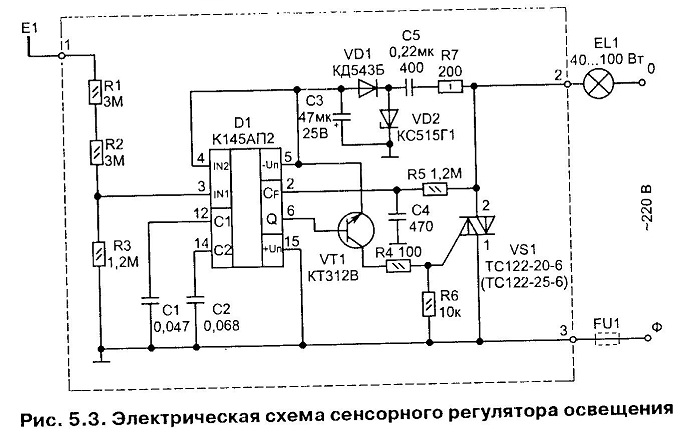
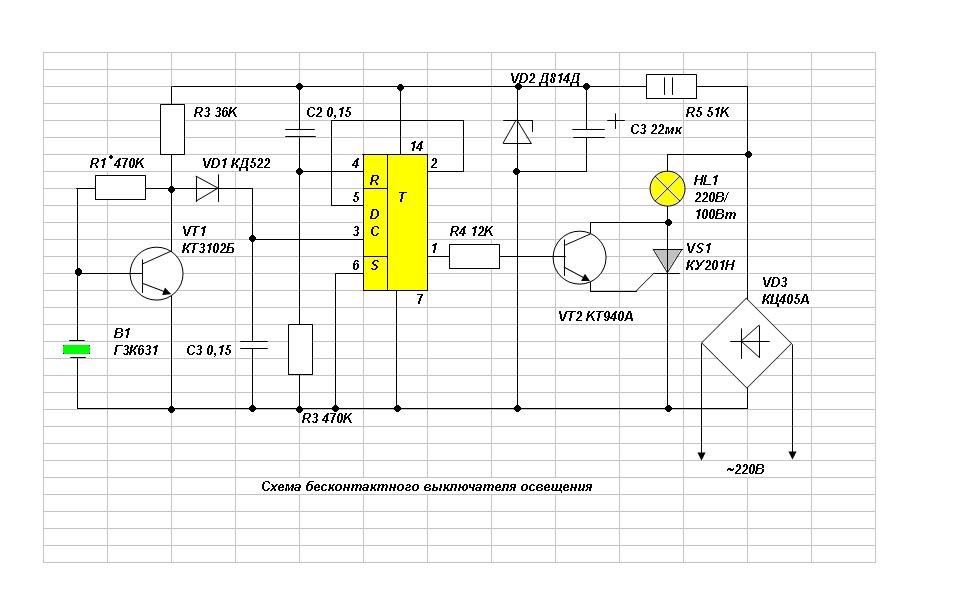
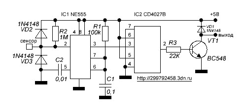
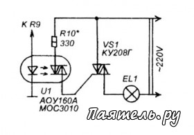
Circuit elements
Let's start by deciding what elements we need for the lighting dimmer circuit.
In fact, the circuits are quite simple and will not require any scarce details; even a not very experienced radio amateur can deal with them.
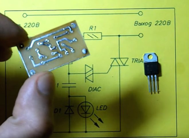
- Triac. This is a triode symmetrical thyristor, otherwise it is also called a triac (the name came from the English language). It is a semiconductor device, which is a thyristor variety. It is used for switching operations in 220 V electrical circuits. The triac has two main power outputs, to which the load is connected in series. When the triac is closed, there is no conduction in it and the load turns off. As soon as an unlocking signal is applied to it, conduction appears between its electrodes and the load is turned on. Its main characteristic is the holding current. As long as a current exceeding this value flows through its electrodes, the triac remains open.
- Dinistor. It belongs to semiconductor devices, is a kind of thyristors, and has bidirectional conductivity. If we consider the principle of its operation in more detail, then the dinistor is two diodes that are connected towards each other. Dinistor is also called diac in another way.
- Diode.This is an electronic element, which, depending on which direction the electric current takes, has different conductivity. It has two electrodes - a cathode and an anode. When a forward voltage is applied to the diode, it is open; in the case of reverse voltage, the diode is closed.
- non-polar capacitor. Their main difference from other capacitors is that they can be connected to an electrical circuit without observing polarity. Polarity reversal is allowed during operation.
- Fixed and variable resistors. In electrical circuits, they are considered a passive element. A fixed resistor has a certain resistance; for a variable, this value can change. Their main purpose is to convert current into voltage or vice versa voltage into current, absorb electrical energy, limit current. A variable resistor is also called a potentiometer, it has a movable output contact, the so-called engine.
- LED for indicator. This is a semiconductor device that has an electron-hole transition. When an electric current is passed through it in the forward direction, it creates optical radiation.
The triac dimmer circuit uses a phase adjustment method. In this case, the triac is the main regulatory element, the load power that can be connected to this circuit depends on its parameters. For example, if you use a triac VT 12-600, then you can adjust the power loads up to 1 kW. If you want to make your dimmer for a more powerful load, then choose a triac with large parameters accordingly.
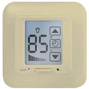
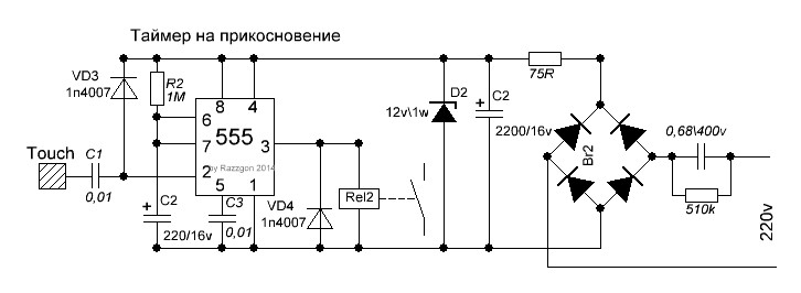
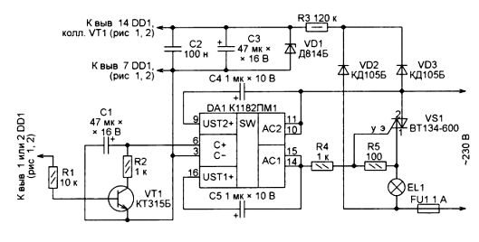
Device Options and Capabilities
The development of a touch switching product equipped with a timer clearly deserves special consideration. Here are the traditional characteristics, such as:
- noiselessness of action;
- interesting design;
- safe use.
In addition to all this, another useful feature is added - a built-in timer. With its help, the user gets the opportunity to control the switch programmatically. For example, set the on and off time in a certain time range.
A unique switch development option with an embedded timer functionality. With the help of such devices, the possibility of controlling lighting at a strictly specified time opens up. Saving electricity is obvious
As a rule, such devices have not only a timer, but also an accessory of a different kind - for example, an acoustic sensor.
In this variant, the device works as a motion or noise controller. It is enough to give a voice or clap your hands and the lamps in the apartment will light up with a bright light.


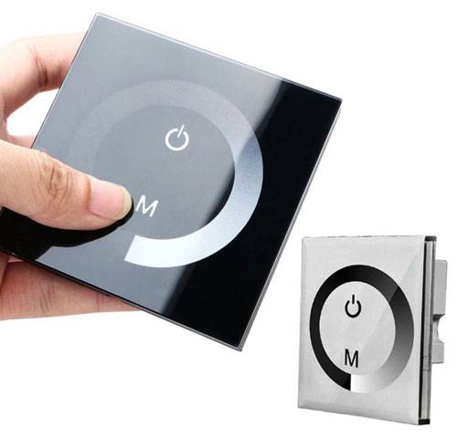
By the way, in case of too high brightness, there is another functionality - dimmer adjustment. Touch-type switches equipped with a dimmer allow you to control the intensity of light.
Modification of touch devices - acoustic switch. It operates according to a slightly different methodology, but it is also a device that supports sensor technologies. In this case, the sensor element is a sensitive microphone.
True, there is one nuance for such developments. Dimmers generally do not support the use of fluorescent and LED lamps in fixtures. But the elimination of this shortcoming is most likely a matter of time.
What does the market offer?
A wide range of wireless remote switches allows you to choose a product based on price, features and appearance.
Below we consider only a few models that the market offers:
- Fenon TM-75 is a remote-controlled switch made of plastic and rated for 220 V. The features of the device include the presence of two channels, a 30-meter range, a remote control and a delayed turn-on function. Each channel can be connected to a group of lighting fixtures and controlled. The Fenon TM-75 wireless switch can be used with chandeliers, spotlights, LED and track lights, as well as other devices powered by 220 volts.
- Inted 220V is a wireless radio switch designed for wall mounting. It has one key and is installed in combination with the receiving unit. The operating voltage of the product is 220 Volts, and the range is 10-50 meters. The wireless light switch is mounted using self-tapping screws or double-sided tape. The body is made of plastic.
- INTED-1-CH is a light switch with remote control. With this model, you can control the light sources remotely. The power of the lamps can be up to 900 W, and the operating voltage of the product is 220 V. Using the radio switch, you can control the equipment, turn on and off the light or alarm. The product is based on a receiver and a transmitter. The latter has the form of a key fob, which has a small size and transmits a signal over a distance of up to 100 m. The body of the product is not protected from moisture, so additional protection must be provided when installed outdoors.
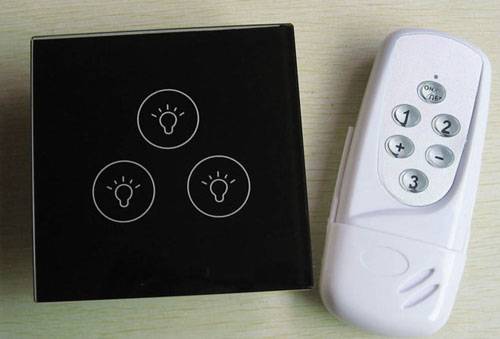
- Wireless touch switch controlled via remote control.The product is wall-mounted, small in size and made of tempered glass and PVC. The operating voltage is from 110 to 220V, and the rated power is up to 300W. The package includes a switch, remote control and bolts for attaching the accessory. The average life cycle is 1000 clicks.
- Inted 220V for 2 receivers - wireless light switch for wall mounting. Management is made by means of two keys. The body is made of plastic. The operating voltage is 220 V. The number of independent channels is 2.
- BAS-IP SH-74 is a wireless radio switch with two independent channels. Management is carried out using a mobile phone on the Android operating system. To work, you need to install the BAS application. Model SH-74 is used to control incandescent lamps with a power of up to 500 W, as well as fluorescent light bulbs (power limit - 200 W).
- Feron TM72 is a wireless switch that controls lighting at a distance of up to 30 meters. Light sources are combined into a receiving unit, and switching on and off is done using the remote control. The TM72 model has two channels, each of which can be connected to a specific group of devices. The product has a large power reserve per channel (up to 1 kW), which allows you to connect various types of light source. A big plus of the model is the presence of a delay equal to 10 to 60 seconds.
- The Smartbuy 3-channel 220V wireless switch is designed to connect light sources to three channels with a power limit of up to 280 W. The rated supply voltage is 220 V. The control is carried out from the remote control, which has a range of 30 meters.
- Z-Wave CH-408 is a wall-mounted radio switch that allows you to program various lighting control scenarios. If necessary, up to eight switches can be connected to it. Of the additional features, it is worth highlighting the management of Z-Wave devices (up to 80) and ease of configuration, regardless of the main controller. The device is powered by two batteries, when they are discharged, a corresponding signal is given. The firmware is updated via the Z-Wave network. The maximum distance to the controller should not exceed 75 meters. Protection class - IP-30.
- Feron TM-76 is a wireless light switch that is controlled remotely using a radio signal. The receiver is connected to light sources, and the remote control controls the receiving unit at a distance of up to 30 meters. The Feron TM-76 model has three independent channels, to each of which you can connect your own group of lighting fixtures. Management in this case will be carried out separately, using the remote control. The maximum power reserve is up to 1 kW, which allows you to connect lamps of various types (including incandescent ones). The operating voltage is 220 V.
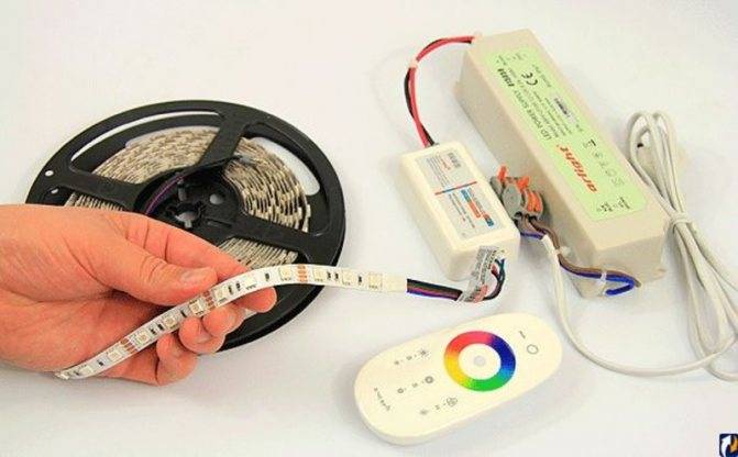
Introduction to Ribbons
Tapes are often installed in a ceiling niche above a specific area in the apartment (for example, above a sleeping place or dining area). Many tenants cannot say exactly what color they need, moreover, over time, the same backlight can get boring. In such a situation, the RGB controller for the LED strip will help out, with which the backlight can be adjusted individually.
The name RGB itself stands for three words - Red, Green, Blue, that is, red, green and blue.It is difficult to choose one color from such a poor offer of color solutions, so many masters recommend installing controllers. Thanks to these devices, residents will be able to adjust the colors to their liking, for example, yellow, orange, purple, as well as adjust their intensity.
Before you buy LED strips, you need to understand a little about their classification. Usually there are two of them:
- SMD 3528;
- SMD 5050.
Both types of tapes differ in dimensions and parameters: the first has sides of 3.5 mm by 2.8 mm, the second has 5 mm by 5 mm, which is reflected in the names themselves. The abbreviation SMD stands for Surface Mounted Device.
Another important feature is the power of the luminous flux. For SMD 3528, it is lower, since in such a tape the LEDs are single-chip, while in SMD 5050 they are three-chip. The second type will shine brighter, but it will consume 3 times more power.
An important parameter is the number of LEDs per 1 meter of tape, where there can be 30, 60, 120 or 240 pieces. The more LEDs, the brighter the backlight will shine. But ribbons with a lot of small bulbs will cost more. Experts advise not to purchase too bright devices, since 60 diodes per 1 meter are enough to illuminate a niche in the ceiling. To decorate furniture, you can purchase the simplest tape with 30 diodes. Such recommendations are optimal for any interior.
To install lighting in a ceiling niche, for example, you can take a SMD 5050 type tape containing 60 diodes per 1 meter. It has the following characteristics:
- the color of the diodes is RGB, that is, multicolor;
- the number of diodes - 60 pieces per 1 meter;
- power - 14 W / m;
- voltage - 24 V.
Also on the package will be presented the abbreviation IP with numbers adjacent to it. This characteristic indicates the degree of protection. For example, the box says IP33, which means the following:
- The first digit 3 indicates the degree of protection against ingress of foreign bodies and other contacts with the lighting device. On a scale of 0 to 5, it indicates protection against fine particles up to 2.5 mm in size.
- The second number 3 indicates the degree of protection against water. The LEDs are protected against sloping splashes at an angle of up to 60 degrees.


The tape is wound on a reel (or reel), its standard length is 5 meters, so it is best to purchase two reels, since it often takes from 5 to 8 meters, and sometimes more, to illuminate various niches. The device is conditionally divided into several small sections, each of which has 6 LEDs. The segments are a completely independent lighting device that will light up when connected to the network.
The LED strip is very plastic, so it can be mounted in niches of any complexity and shape, not to mention straight lines and transitions. On the reverse side of the LEDs there is a sticky double-sided adhesive tape, thanks to which the colored design will firmly adhere to any surface.
Advantages
Classical and walk-through touch switches can boast numerous positive characteristics. The main ones include:
- Silent operation of the executive main module, which is built into the switch.
- The installed practicality of the switching circuit.
- Complete safety of the product operation, since the power is supplied galvanically through the isolation.
- A modern look that will fit into any interior.
It is worth noting that improved products can be touched even when wet, which is not recommended to be done with hands with keyboard instruments. touch Setting the switch is not a difficult process, thanks to this, the master can complete the mechanism Functional remote control.
Some features of branded switches
In addition to the usual functions of switching on and breaking the movement of current by touch, many companies that produce sensor-type control systems equip them with additional units. It may well be a system of interconnection between two identical devices or remote control. The first case is quite interesting in that to control the supply of energy, you can use not one device, but several. By changing the state of any of them, the others switch to the selected mode of operation. In addition, the use of such technology is justified in smart home complexes or alarm systems, where, in addition to manual control, automatic control is used. An example would be a security system. When penetration is detected, the light turns on, producing a psychological effect on the intruder, at the same time highlighting it for better video and photo shooting.
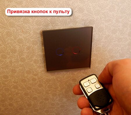
Setting up the remote control
Touch switches look really very stylish - they will look great in the hall, and in the corridor, and in the kitchen, and anywhere else. And such devices are good because they can be controlled remotely. To do this, you just need to order a universal remote control over the Internet. The price of this device, which is a keychain with a carabiner and a metal front panel, is not so high.
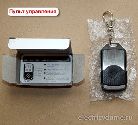
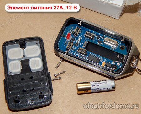
There are four buttons on the remote control panel, they are designated in Latin letters - A, B, C, D. This device works on a 27A battery with a voltage of 12 volts. Such a remote control is compatible with a variety of touch switches, in particular, with popular LIVOLO brand switches of the C6 and C7 series.
Setting up this remote control is easy. First of all, you need to press the touch switch button (at the same time, it should be in the “off” position) and hold it until the “Pi” sound signal is heard from the touch device - in time it is about 5 seconds.
Then you should press one of the buttons on the remote control (A, B or C), as a result of which another beep should sound - it means that the “binding” procedure is completed. Now the button that we pressed on the remote during binding can be controlled (disabled, enabled) by touch switches from a distance. All other buttons on the switches are tied to the remote control in exactly the same way.


It is worth noting that several touch devices can be tied to one button of the remote control. That is, several buttons and even several remotes can be tied to one sensor. There is information on the Internet that you can make 8 such bindings (I haven’t tried it myself).
| At the same time, the D button has a slightly different function than all the others - it is designed to turn off all three lines at once. |
Detaching the sensor from the remote control is also very simple. To do this, touch the sensor and hold it for about ten seconds.
After five seconds, the first beep will sound, but this should not be taken into account.And only when one more, second beep sounds, all previous settings will be reset
The operating range of the VL-RMT-02 universal remote control is 30 meters. This is quite enough for everyday use - the remote control will properly perform its functions throughout the entire territory of an ordinary apartment.
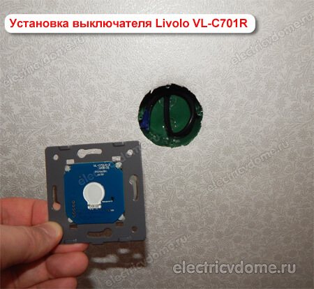
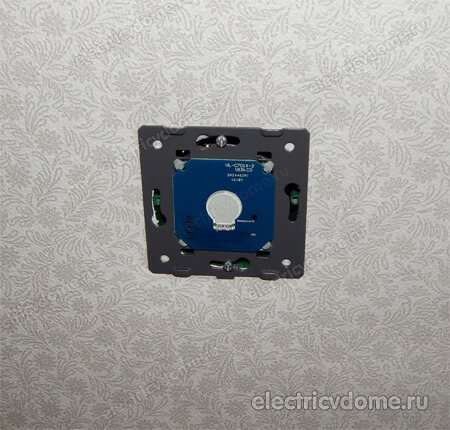
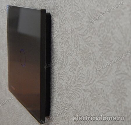
Connecting a single-key touch switch Livolo VL-C701R
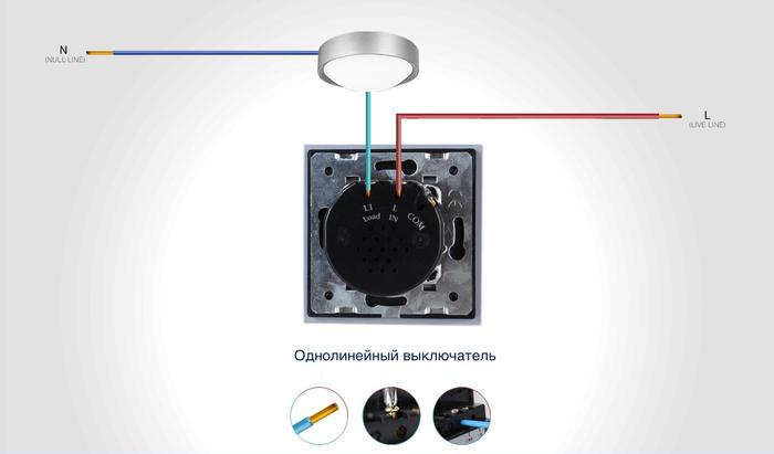
So let's figure out how to connect touch light switch 220 volt. In fact, it is no different from the connection diagram of a single-gang switch.
There are two terminals on the switch body marked as "L-in" and "L-load". Terminal "L-in", the literal abbreviation of which sounds like - "live line terminal". If you use the electrical translation, it means something like this: "live line" - live line, "terminal" - contact, contact screw. In general, this is a contact for connecting a PHASE wire (the one that came from the junction box).
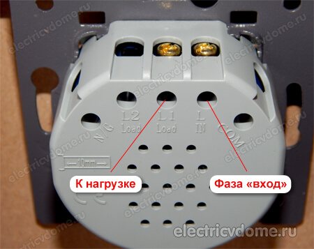
The “L-load” terminal in the instruction manual is called “lightin terminal”, it translates something like this: “lightin” - lighting devices, “load” - load. That is, this is a contact for connecting a wire that goes to a lighting load (a wire that goes to a lamp or chandelier).
As you can see, there is nothing complicated in this “electronic miracle”, everything is like in a conventional switch, there are two terminals “phase-input”, “phase-output”. We strip the wires to the desired length and connect to the terminals.
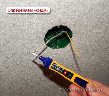
If you install a touch switch instead of the old one, simply unscrew the wires from the old one and connect it to the new one. The main thing is to decide where the phase is and connect it to the desired contact of the touch light switch (“L-in” contact).
The only thing I would advise, if you use a cable with a stranded core, use NShVI lugs. The touch switch has screw-type terminals, and if you push a bare stranded core there when tightening, you can easily crush it.


And this is what the Livolo switch looks like from the side
The relationship of mechanisms
To correctly connect the touch switch, you need to know what each node is responsible for. The classic device operates according to the following scheme:
- A weak signal is formed on the sensitive element, which is fed to the input of the installed microcircuit. In this place, the incoming information wave is amplified to the desired value, after which the triac electrode is fed through the control transistor. All share manipulations are performed in seconds.
- The opening time of the output control of the element is adjusted depending on the duration of switching on If.
- transistor, the user holds the switch on his fingers for a long time, then the current in the supply circuit will rapidly increase. In such a situation, the illumination in the same room will increase.
- To turn off the fingers, the light must be kept on the sensor and after reaching the maximum brightness of the light flux.
If a beginner wants to figure out how it works then, the sensor needs to study in detail the circuit of a classic unit. For self-manufacturing of a sensitive pad, you can use the usual copper Rules.
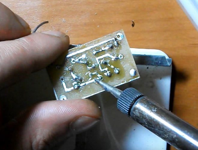
Circuit Assembly
Now we come to putting together our dimmer. Keep in mind that the circuit can be mounted, that is, using connecting wires. But it will be better to use a PCB. For this purpose, you can take foil textolite (35x25 mm will be enough).The dimmer, assembled on a triac using a printed circuit board, allows you to minimize the size of the block, it will have small dimensions, and this makes it possible to install it in place of a conventional switch.
Before starting work, stock up on rosin, solder, a soldering iron, wire cutters and connecting wires.
Next, the regulator circuit is assembled according to the following algorithm:
- Draw the connection diagrams on the board. Drill holes for connecting elements. Using nitro paint, draw tracks on the diagram, and also determine the location of the mounting pads for soldering.
- Next, the board must be etched. Prepare a solution of ferric chloride. Take the dishes so that the board does not lie tightly on the bottom, but with its corners, as it were, rests against its walls. During etching, turn the board over periodically and stir the solution. In the case when this needs to be done quickly, warm the solution to a temperature of 50-60 degrees.
- The next step is tinning the board and washing it with alcohol (it is undesirable to use acetone).
- Install the elements into the holes made, cut off the excess ends and use a soldering iron to solder all the contacts.
- Solder the potentiometer using the connecting wires.
- And now the assembled dimmer circuit is being tested for incandescent lamps.
- Connect the light bulb, turn on the circuit in the electrical network and turn the potentiometer knob. If everything is assembled correctly, then the brightness of the lamp should change.