- What mistakes can be made?
- Changing a conventional switch under the gate
- Where is the device placed?
- Connection diagram to the junction box
- Toggle switch option with a hidden mechanism
- Installation diagram of several switches
- Video - Connecting a walk-through switch
- Why are pass switches needed?
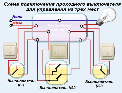
- Lighting control from three points with toggle switches
- How to connect a pass switch
- Toggle switch
- The principle of operation of the pass switch
What mistakes can be made?
Naturally, with the inability to read the installation diagram of the Lezard double-gang switches, you can make a lot of mistakes. And the very first happens when looking for a common contact. By mistake, some people think that the common terminal is the one that is located separately from the other two. And it's not like that at all. Of course, on some models such a "chip" can work, but this happens quite rarely.
And if you assemble the circuit with an error, the switches will not work correctly, no matter how many times you click them
The common contact can be located anywhere, so it is important to find it, focusing on the diagram or instrument readings. Quite often, such problems arise when installing or replacing pass-through switches from different manufacturers.We looked at the information one at a time, connected it correctly, and the second turned out to be from another manufacturer
And it was connected according to the same scheme, but it does not work. To restore functionality, you need to find a common contact and connect all the wires correctly. This step is the main one, how the whole system will work in the future directly depends on it. There is no need to focus on chance, it is better to make sure several times that the contacts are correctly defined. And in order not to forget, you can mark them with a marker. Thus, of course, so that these marks are not visible from the outside
We looked at the information one at a time, connected it correctly, and the second turned out to be from another manufacturer. And it was connected according to the same scheme, but it does not work. To restore functionality, you need to find a common contact and connect all the wires correctly. This step is the main one, how the whole system will work in the future directly depends on it. There is no need to focus on chance, it is better to make sure several times that the contacts are correctly defined. And in order not to forget, you can mark them with a marker. Thus, of course, so that these marks are not visible from the outside.
But it also happens that the device that you use is not a pass-through
Therefore, when buying, you need to pay attention to what type of device is a pass-through or a regular two-key one. It is also worth mentioning the incorrect connection of cross devices. Some electricians put the wires from the first switch on the contacts located at the top
And from the second switch - to the contacts below. But you need to do it a little differently - connect all the wires to the device crosswise.Only in this case, the whole structure will be able to function correctly.
Some electricians put the wires from the first switch on the contacts located at the top. And from the second switch - to the contacts below. But you need to do it a little differently - connect all the wires to the device crosswise. Only in this case, the whole structure will be able to function correctly.
Changing a conventional switch under the gate
When studying a photo of a pass-through switch in the network, it becomes clear that the differences of this type from the usual one are minimal. And therefore, if there are a couple of ordinary elements in stock, they can be easily converted into an improved look. Especially, if it comes about active devices. Thus, it will be possible to save not only on the cost of electricity, but also on the purchase of additional devices.
The instruction on how to make a pass-through switch from a standard one implies the presence of a pair of switching devices manufactured by the same company and one release format (key shape, size, color). Moreover, you will need a single-key and two-key varieties.

It is important to pay attention here that the two-key type of device has terminals that allow changing places. This is important to ensure an independent process of closing and opening the network. In other words, in one position of the key, the first network will be turned on, in another position, the second one.
In other words, in one position of the key, the first network will be turned on, in another position, the second one.


The algorithm of actions will look like:
- at the point of attachment with a probe, determine which of the wires running in the wall (over the wall) is the phase wire and mark it with a color, this will facilitate the installation process;
- if the element is active, and not new, you will need to de-energize it and remove it (loosen the contact clamps and each socket screw);
- on the reverse side of the removed device, open the clamps on the case and remove the electrical component;
- using a thick screwdriver (slotted type), the spring pushers are carefully removed from the frame to avoid damage to the elements;
- the same screwdriver pry the teeth on the ends of the extracted mechanism;
- one of the moving rocker contacts located on the electrical part will need to be turned a full turn (180 °);
- cut off one of the common contact areas (without subsequent insulation);
- return the removed elements to their place;
- if we are talking about an active element, you will need to install it in its original place;
- remove the key from the single-key switch and put it on the assembled structure;
- install the second switch on the planned control point, connecting it to the first three-wire cable;
- connect the circuit together in a junction box.

In the case of switches installed during repair, the presence of an improved switch can be taken into account in the design. If we are talking about an autonomous alteration of control points for an electrical device, the process will be more complicated.


At first, after installing the considered types of switches, whether they are from the factory or made independently, there may be confusion in use due to some features of the devices, since it will no longer be clear by the position of the key whether the device is on or off.

Also, the network will not be available simultaneously from both (all) points of control.At one point in time, the command must be given from one point. However, the initial unfamiliarity will not override the benefits of the installation.

Where is the device placed?
As a rule, pass-through switches are mounted in different zones so that they are convenient to use. At this is not necessary use two switches. So, one of them can become the main, and the other auxiliary.
If the electrical wiring was located in a corrugated tube, then when installing a pass-through device, it will be possible to replace it without breaking the floors.
 Wiring in a corrugated tube
Most often, standard walk-through switches with one or two keys are placed at such points:
- On both sides of a narrow corridor. If the door is located in the center, then it will also be possible to install the device near it.
- In spacious bedrooms. So, one switch can be installed according to the standard at a distance of 30-40 centimeters from the door jamb, and the other above the bed.
- On the landing.
- Along the path in the courtyard of a private house. After all, it will be convenient to go for a walk in the evening, and if necessary, turn on and off the light along the way.
- In the halls of a large area, where there are several entrances on the sides.
The use of a pass-through switch is advisable not only to save electricity, but also necessary for the safety of movement. It turns out that the only drawback is the complexity of the installation for some wizards.
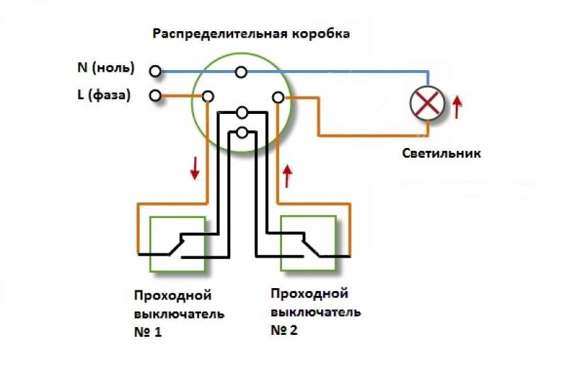
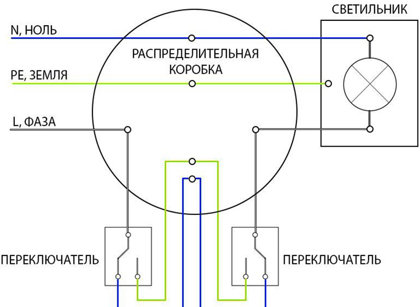
Connection diagram to the junction box
Of particular interest is the connection diagram of the backup switch in the junction box. Partially, we touched on this issue above.
Let's take a closer look.
It includes four three-wire wires:
- with AV lighting switchboard;
- on the first switch;
- on the second switch;
- to the light source.
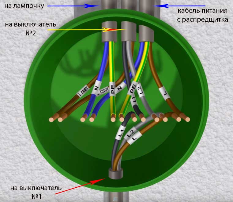
When connecting wires you have to look at the color. When using a VVG cable, the following markings apply:
- White - phase.
- Blue is zero.
- Yellow-green - earthy.
A second type of marking is also possible - white, brown and black, respectively.
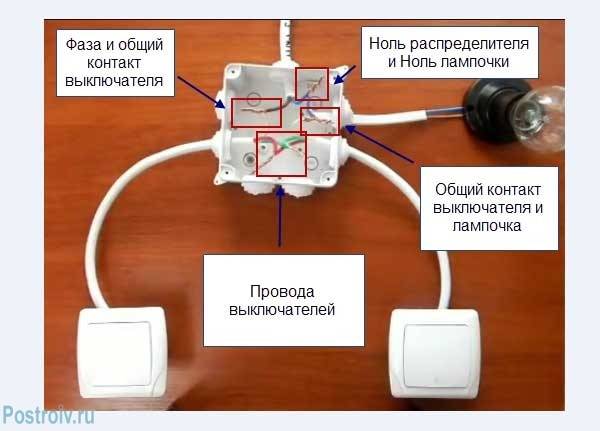
When assembling, proceed as follows:
- Connect the zero of the input AB cable and the neutral wire that goes to the lamp at one point using the car terminals.
- Connect the ground wires (if provided).
- Connect the yellow-green wire to the lamp body.
- Connect the phase wires. To do this, combine the phase from the input with the phase of the terminal of the first pass.
- Using a separate clamp, combine the common wire of the second passthrough with the phase of the wire going to the lighting device.


After completing the above steps, connect the secondary (outgoing) cores to the first and second switches.
In this case, the principle of association does not matter. Even if there is an error in the color coding, the scheme will work correctly. After that, you can apply voltage and check the health of the circuit.


There are a few things to keep in mind when using this connection:
- Make sure that the phase comes to the common wire of the 1st switch.
- The same phase wire must go from the common wire of the 2nd switching device towards the lamp.
- The other two conductors are combined with each other in a junction box.
- Zero and ground wires are fed directly to the lamps.
Toggle switch option with a hidden mechanism
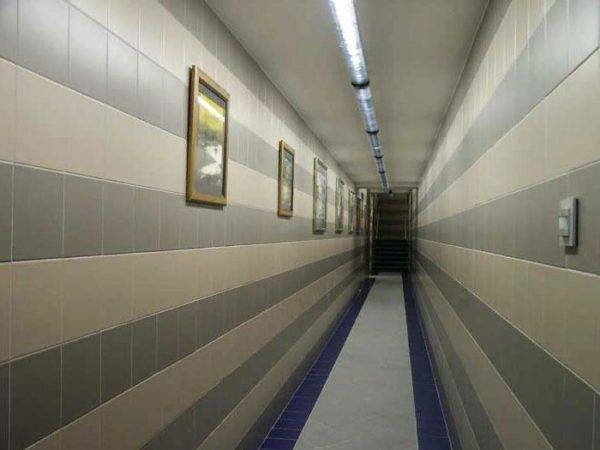
 Reversing switches are used in public premises of a large area and those that have opposite exits (in walk-through galleries, tunnels, corridors). In most cases, pass-through switches are installed in their usual place at the entrance and exit. In the apartment, switches are placed in a convenient place, for example, one stands at the entrance to the bedroom, and the second is located near the bed.
An internal switch is mounted if wired hidden wiring in the walls on previously made furrows. A corrugated hose is put on the wires. A mounting hole is drilled under the switch in the thickness of the wall using a crown. The body of the box is fixed with gypsum or self-tapping screws.
The box for installing the pass-through type switch is taken spacious, since it contains bundles of wires and cables pass to other devices and fixtures. After laying the wire from the switchboard, the conductors are connected to the contacts of the switch according to the developed scheme.
Lamp contacts are connected to the neutral wire. The phase is connected to one of the PVs. The contacts are connected in series through the junction box in the room, after which they are sent to all lighting fixtures. For ease of use, cables are marked or products of different colors are immediately used.
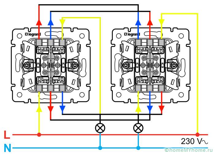
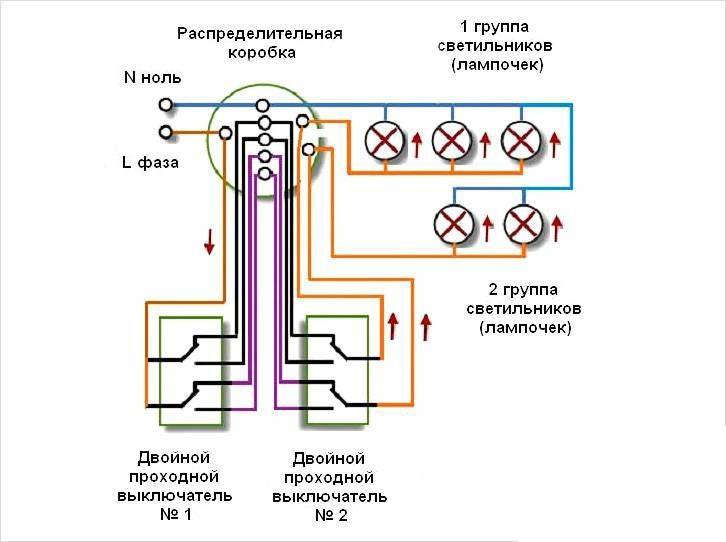
Installation diagram of several switches
We have analyzed how to install switches in the presence of one or two or three groups of lighting fixtures. After all, only two switches were required there, which are located along a common line.
Now we have to consider the situation when there are several switches at different points. The bottom line is that they must all control the same lamp.
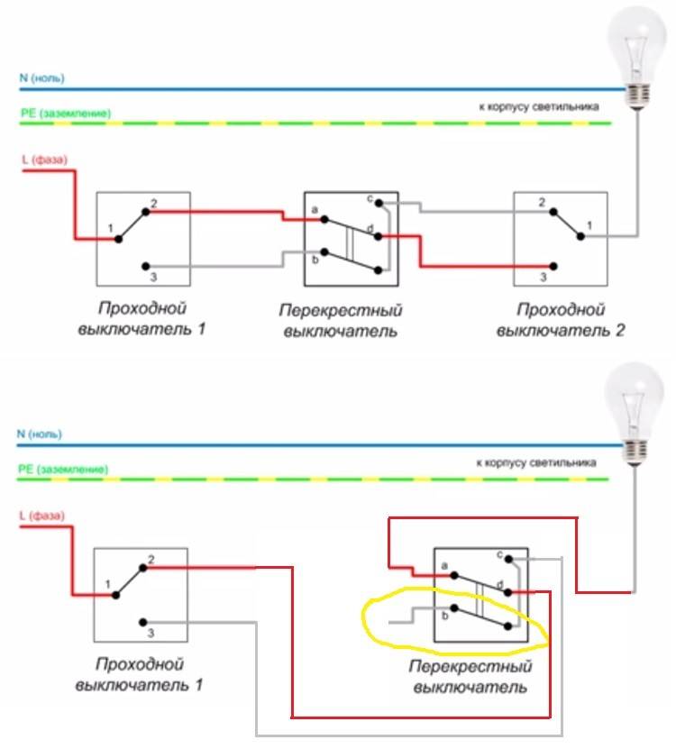
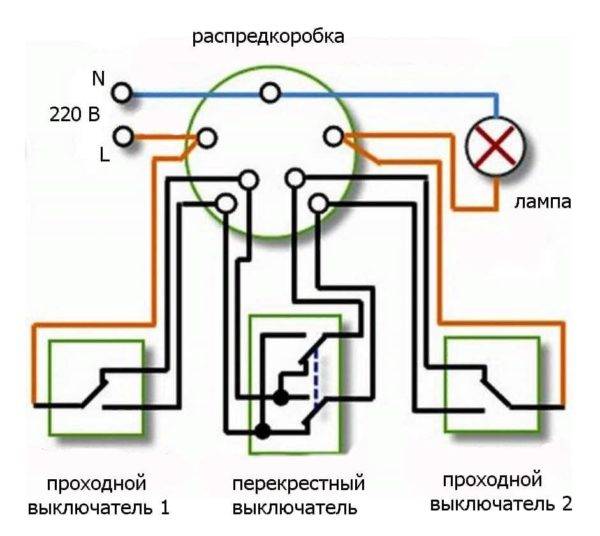
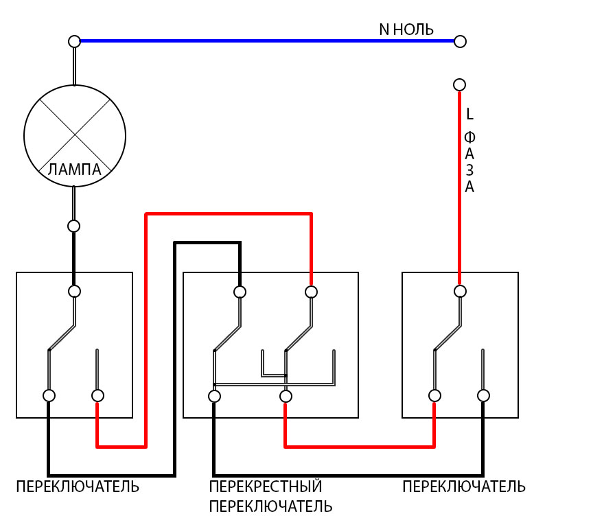
If it is necessary to organize the control of a lighting device from three or more places, it will not be possible to use another switch, except for a cross one. Here one chain is incoming.
 Here one chain is incoming
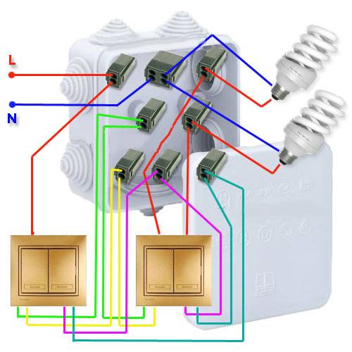
Switches located on both sidesare connected according to the standard scheme. Only between them is another one that has four clips for connecting wires. After clicking on one of the keys in this system, the connected contacts open, and a cross circuit occurs in the new circuit.
Of course, in addition to standard single-key devices, multi-key cross switches are often used. Such a connection is required if there are several groups of luminaires. However, here too you will have to make more connections with clamps. In addition, an inexperienced master will easily confuse the veins, so care should be taken.
If it is required to install an additional “make-break” point, then another cross-switch is mounted with wiring connected to the already installed device.
 Cross switch
Masters recommend making electrical wiring connections by passing the conductors into the junction box. However, for some people it is easier to do this by bypassing the box with a wire and two strands.
As noted in practice, this is a rational connection method that does not violate safety regulations. In addition, such a connection allows you to reduce the cost of purchasing additional wires.
 Common Connection Mistakes
Video - Connecting a walk-through switch


Although the process of installing a cross switch seems simple, it is necessary to follow the exact instructions in order not to make a mistake. Otherwise, such a device simplifies the process of controlling the lamp - you only have to choose a switch in accordance with the rules.
Why are pass switches needed?
Turning on the light in a long dark hallway can be quite inconvenient if there is only one switch located at the end of the room. The most rational installation of pass-through switches (another name is cross switches) in different sides of the room.
So it will be possible to turn on, turn off the light immediately after entering the corridor. This is especially true in the entrance of the house, where the apartments are located in one line along a long landing, on flights of stairs, in offices, industrial premises.
Another use case for such a control scheme is a large bedroom with several beds. If you install walk-through switches at each bed, you can turn on the light without getting up. The installation of such devices is justified in summer cottages, personal plots, courtyards of private houses. You can turn on the light at the exit from the house - after the completion of business there is no need to go in the dark.
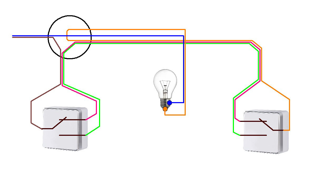
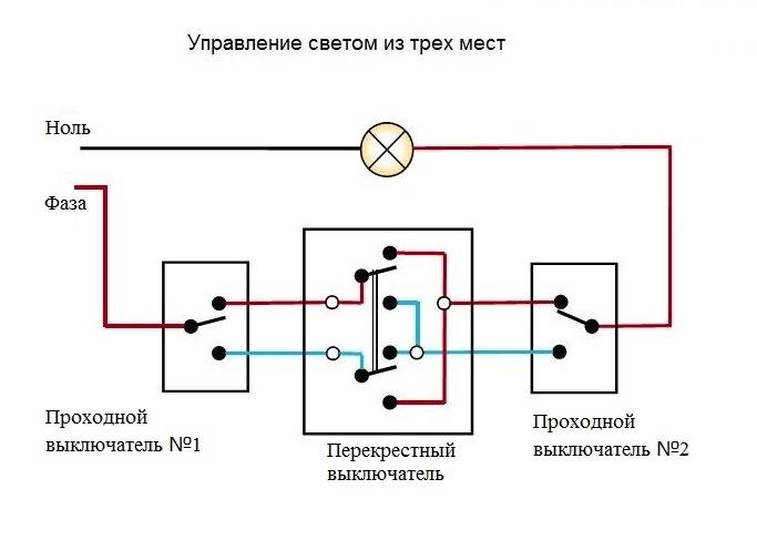
Lighting control from three points with toggle switches
In the same case, if it is necessary to carry out the installation of through switches from three points to control the electrical circuit, toggle switches are used. The usual ones, which we reviewed above, have only three contacts. And with their help, it will be quite problematic to implement the connection.The difference between the toggle switch and the one discussed above is that it has four contacts - two at the bottom and two at the top. The scheme turns out such that two through passages are placed at the extreme points, and between them there are crossovers.
In order to carry out the installation of walk-through switches from two points, it is enough to follow the recommendations that we indicated earlier. But to control a circuit of three or more points, you will need to connect several more devices in between. To do this, you need to find the secondary (that is, not the main) wires in the junction box, coming from the two extreme switches.
Now it remains only to disconnect these wires correctly. It is better to adhere to such a scheme so that there are no troubles:
- The wires coming from switch "1" must be connected to the input.
- The wires that go to switch "2" are connected to the output of the switch.
A little further we will talk about how to properly connect. Be sure to familiarize yourself with the installation diagram of the Gira two-gang push-button switch. It may differ slightly from the one we present in our article.
Of course, the toggle switch should not be mounted in the box itself, but in any other convenient place. To connect it, you must use a wire with four cores. Just insert it into the junction box and connect it correctly to the wires. Now you can control lighting from three points at once. This will be especially useful if you are installing lighting for a three-story house.
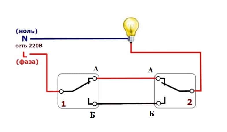
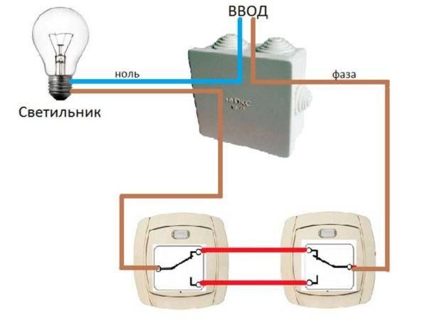
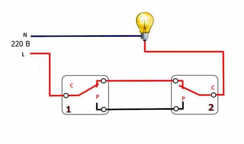
How to connect a pass switch
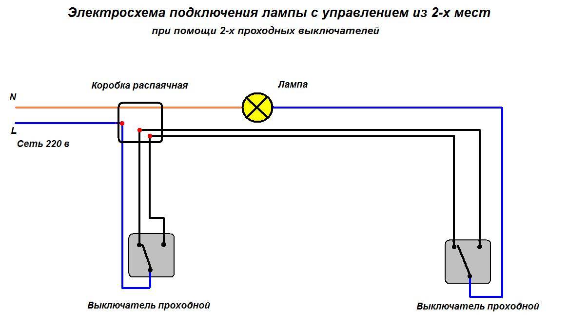
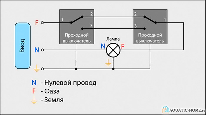
Procedure pass-through switch connection almost indistinguishable from the usual.The difference is only in the number of contact terminals and wires - the pass-through switch has three of them.
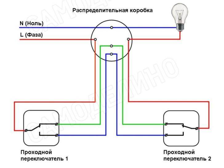
The circuit uses two feed-through switches and a junction box, into which wires from a controlled lamp and three-wire wires from switches are connected. The cross section of the three-core wire supplied to the feed-through switches must be selected in accordance with the power of the controlled luminaire (1).
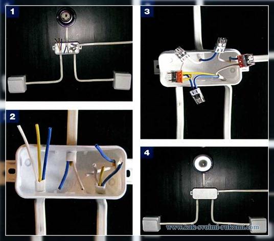
Strip the ends of the electrical wires, removing the insulation from them by 5-7 mm. The length of free wires should not exceed 10 cm - a very long wire will not fit in the box, and it will be inconvenient to work with a very short one (2).
Assemble the circuit in the junction box.
Only the phase wire should be connected to the switches, when the neutral wire is connected to them, the voltage from the lighting circuits will not be removed, which means that the insulation of the wires will wear out faster and short circuits are not ruled out.
Connect the phase wire from the junction box to the common input contact of the first pass-through switch. Connect the other two (output) contacts to the wires coming from the analogous contacts of the second switch. And connect the common (input) contact of the second switch to the wire coming from the lamp. Connect the second wire from the lamp directly to the zero of the junction box (3).


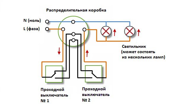
As a source of illumination in such a scheme, any types of lamps - from conventional incandescent lamps to fluorescent, energy-saving and LED (4).
Connecting a pass switch: photo
Before work on connect the wires, turn off the electricity in the house.Make sure that there is no voltage with a voltage indicator and only then proceed to work.
Author : Elena Brazhnik
Toggle switch
Circuit options
Equipped with two inputs and outputs, has four terminals, immediately switches a pair of contacts. used not so often, but in some cases irreplaceable. Facilitates movement in the dark:
- in a large corridor or hall with many doors;
- in an apartment with three levels;
- a bedroom with a switch at the entrance and two next to the bed;
- being in the house, it is possible to control the lamps in the garage, on the terrace, in the gazebo.
To equip the staircase lighting in a three-story building, you need to create three control points. The cross type toggle switch is not used by itself. You need to connect it in the gap between switches. Knowing the order of connecting a pass-through, it is easy to figure out how to make a toggle switch.
Their number can reach up to 10, but they should always be located between the entrances.
The principle of operation of the pass switch
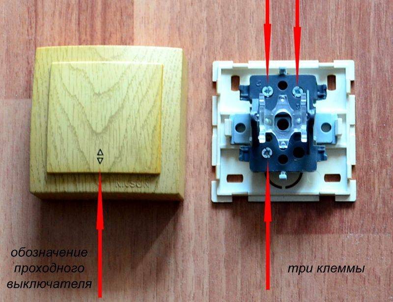
On the key of the pass-through switch there are two arrows (not large), directed up and down.
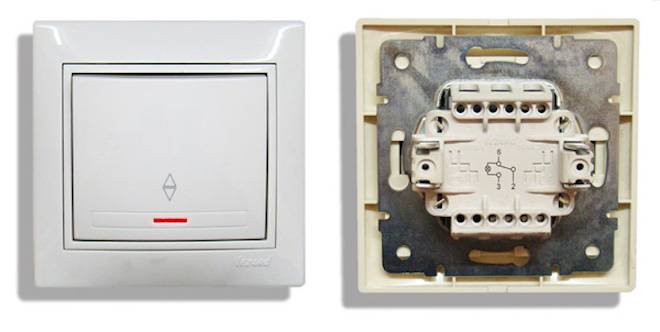 This kind has pass-through single-gang switch. There may be double arrows on the key.
The connection diagram is not much more complicated than the connection diagram of a classic switch. The difference is only in a larger number of contacts: a conventional switch has two contacts, and a pass-through switch has three contacts. Two out of three contacts are considered common. In the lighting switching circuit, two or more similar switches are used.
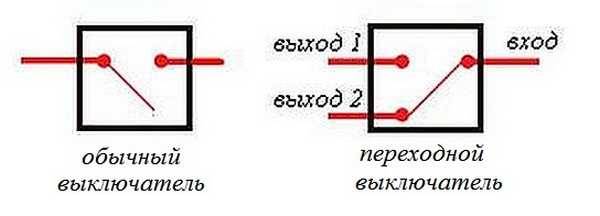 Differences - in the number of contacts
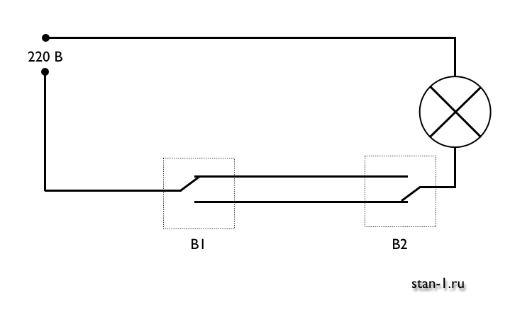
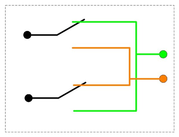
The switch works as follows: when switching with the key, the input is connected to one of the outputs. In other words, the feed-through switch is designed for two operating states:
- Input connected to output 1;
- Input connected to output 2.
It has no intermediate positions, therefore, the circuit works as it should. Since there is a simple connection of contacts, according to many experts, they should have been called "switches". Therefore, the transitional switch can be safely attributed to such devices.
In order not to be mistaken what kind of switch, you should familiarize yourself with the switching circuit, which is present on the switch body. Basically, the circuit is available on branded products, but you will not see it on inexpensive, primitive models. As a rule, the circuit can be found on switches from Lezard, Legrand, Viko, etc. As for cheap Chinese switches, there is basically no such circuit, so you have to call the ends with the device.
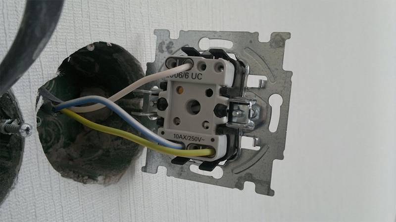
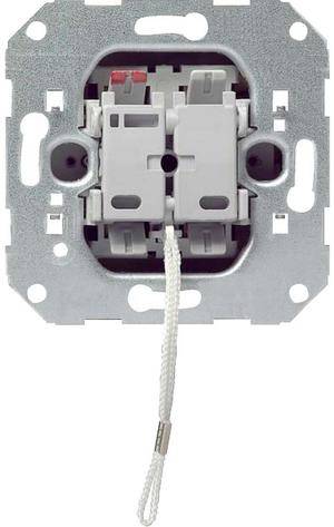
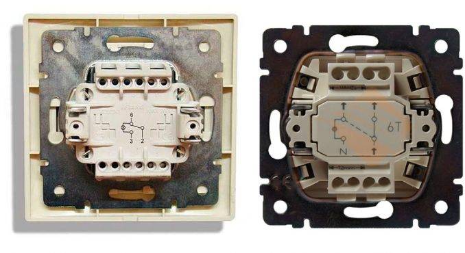 This is the switch on the back.
As it was mentioned above, in the absence of a circuit, it is better to call contacts at different key positions. This is also necessary in order not to mix up the ends, since irresponsible manufacturers often confuse the terminals during the production process, which means that it will not work correctly.


To ring the contacts, you must have either a digital or pointer device. The digital device should be switched to dialing mode with the switch. In this mode, short-circuited sections of electrical wiring or other radio components are determined. When the ends of the probes are closed, the device emits a sound signal, which is very convenient, since there is no need to look at the device display.If there is a pointer device, then when the ends of the probes are closed, the arrow deviates to the right until it stops.
In this case, it is important to find a common wire. For those who have the skills to work with the device, there will be no particular problems, but for those who picked up the device for the first time, the task may not be solvable, despite the fact that you need to figure out only three contacts
In this case, it is better to first watch the video, which clearly explains, and most importantly shows how to do it.
Pass-through switch - how to find a common terminal?
Watch this video on YouTube


