- Do-it-yourself ground loop in a private house
- Ground loop PUE norms
- Grounding installation
- Test work for performance
- Why you can not make separate grounding
- How to do the installation of the ground loop yourself?
- Choose a place
- Excavation
- Assembling the structure
- Entering the house
- Check and control
- DIY grounding device: step-by-step instructions
- Choosing a place for mounting the ground loop
- Excavation work
- Clogging of ground electrodes
- Welding
- backfilling
- Checking the ground loop
- Touch voltage and step voltage
- Grounding schemes: which one is better to do
- TN-C-S system
- TT system
- Let's take a look at the theory
- The role of grounding
- 4 Installation of grounding parts - circuit definition and assembly
- Grounding calculation, formulas and examples
- Ground resistance
- Dimensions and distances for earth electrodes
Do-it-yourself ground loop in a private house
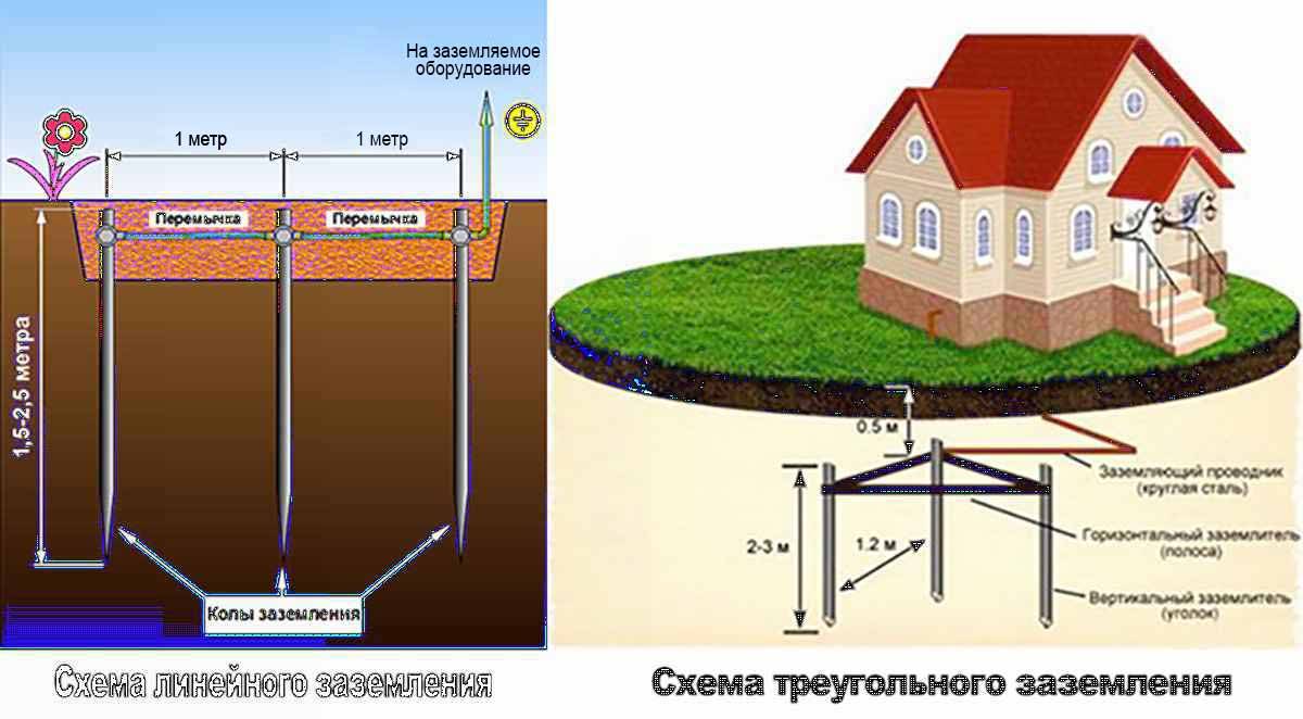
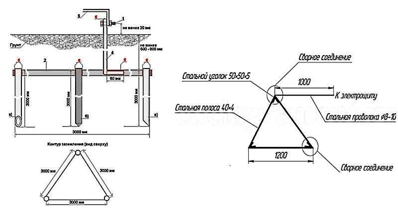
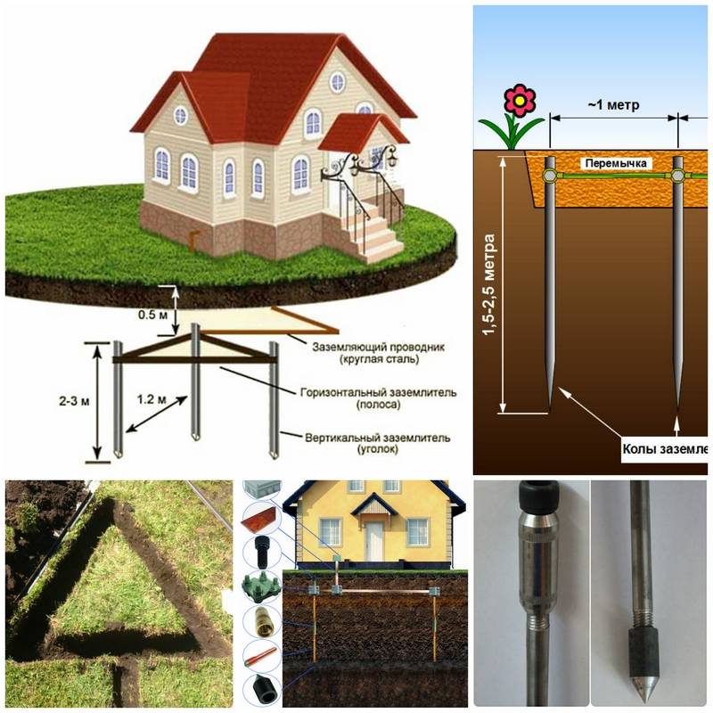
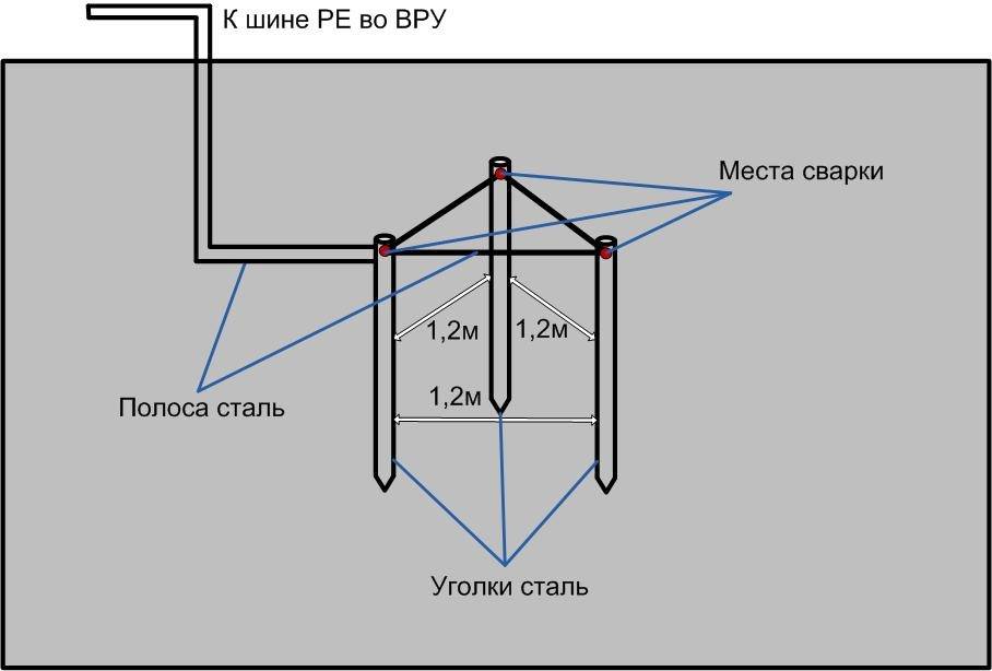
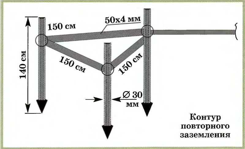
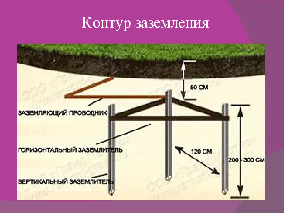
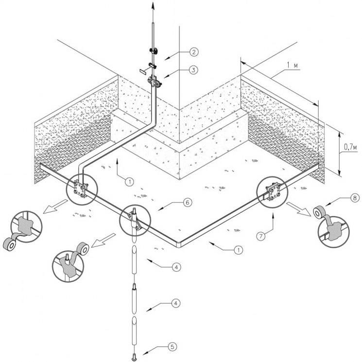
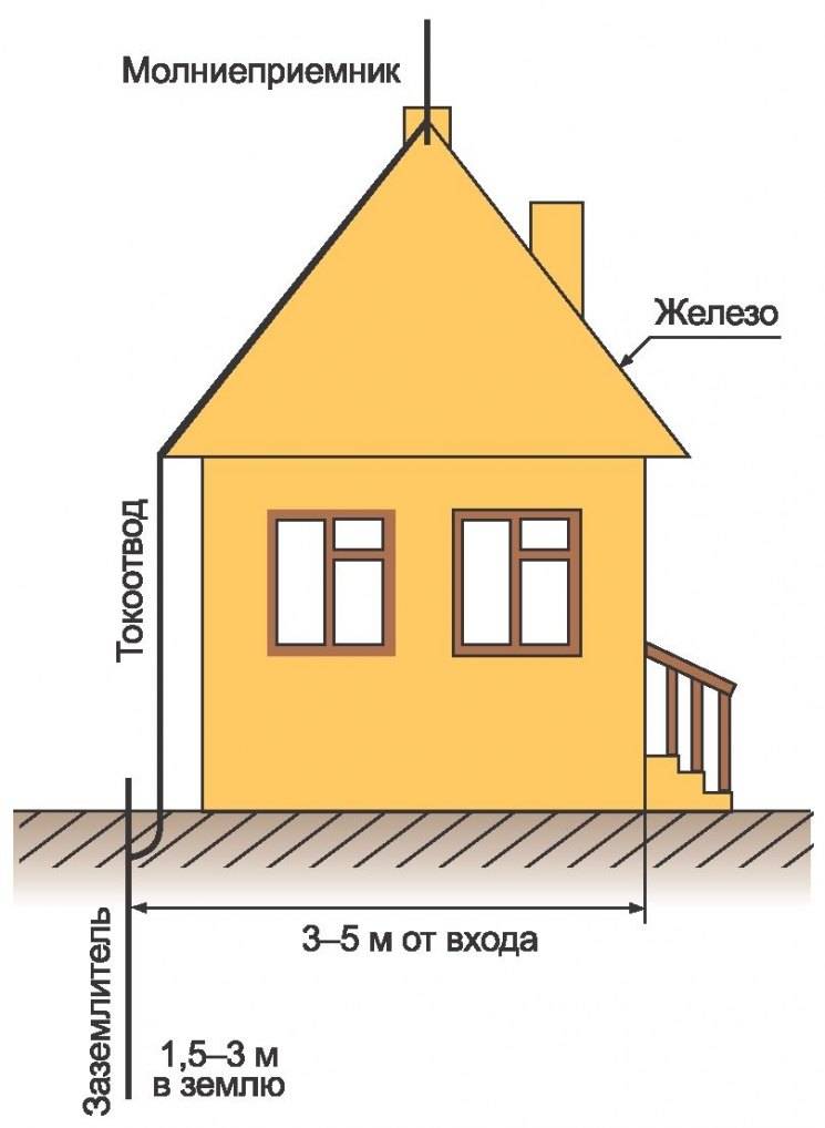
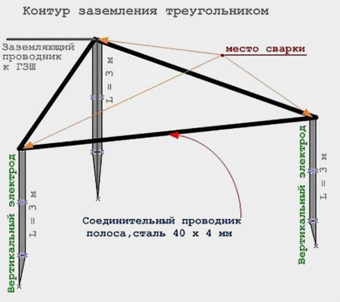
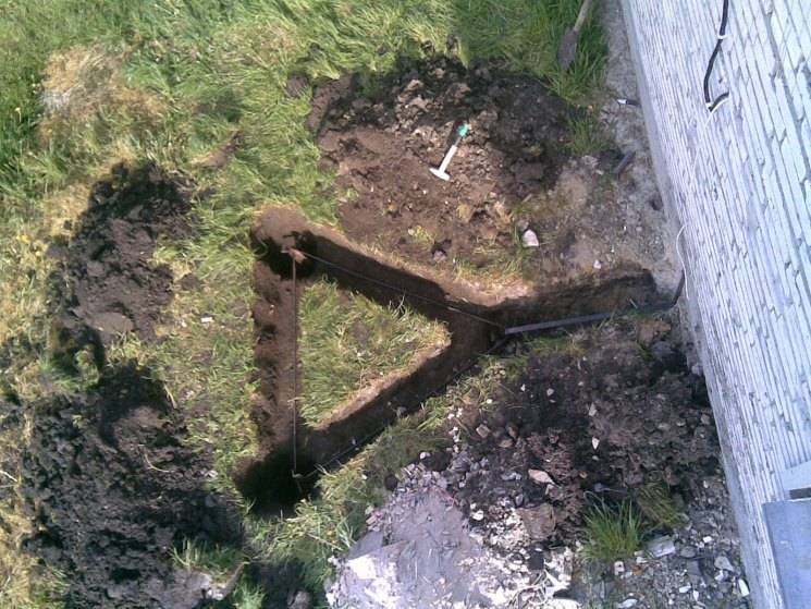
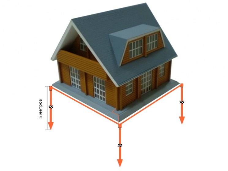
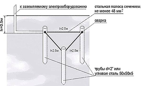
First, let's deal with the shape of the ground electrode. The most popular is in the form of an equilateral triangle, at the tops of which pins are clogged. There is also a linear arrangement (the same three pieces, only in a line) and in the form of a contour - the pins are hammered around the house in increments of about 1 meter (for houses with an area of more than 100 sq. M).The pins are interconnected by metal strips - a metal bond.
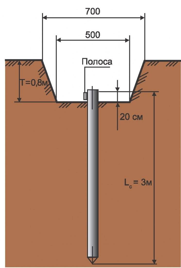
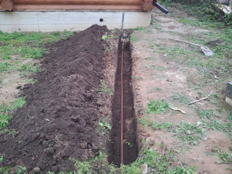
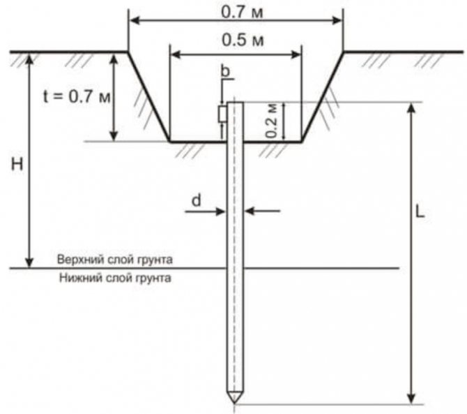
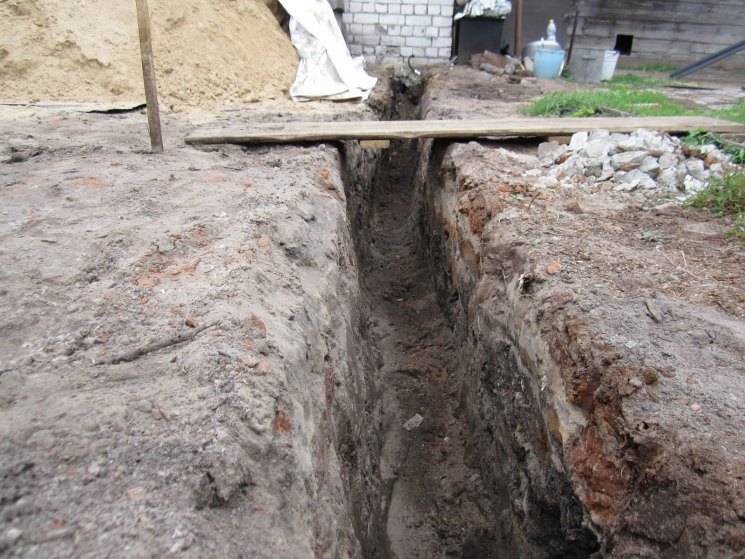
From the edge of the blind area of the house to the installation site of the pin should be at least 1.5 meters. At the selected site, they dig a trench in the form of an equilateral triangle with a side of 3 m. The depth of the trench is 70 cm, the width is 50-60 cm - so that it is convenient to cook. One of the peaks, usually located closer to the house, is connected to the house by a trench having a depth of at least 50 cm.
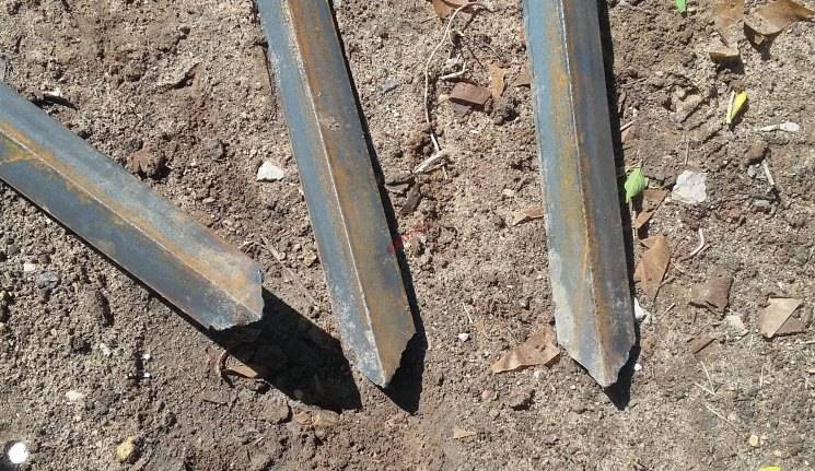
At the vertices of the triangle, pins are hammered (a round bar or a corner 3 m long). Leave about 10 cm above the bottom of the pit
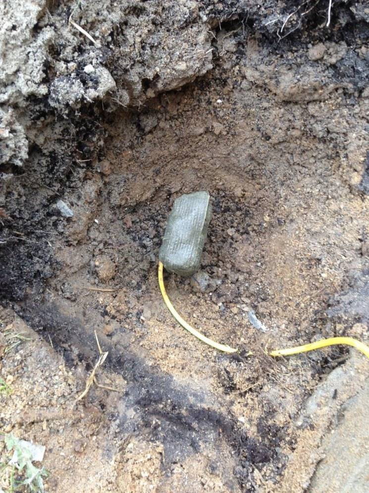
Please note that the grounding conductor is not brought to the surface of the earth. It is below ground level by 50-60 cm
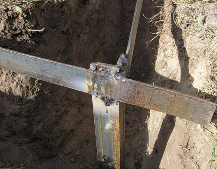
A metal bond is welded to the protruding parts of the rods / corners - a strip of 40 * 4 mm. The created grounding conductor with the house is connected with a metal strip (40 * 4 mm) or a round conductor (section 10-16 mm2). A strip with a metal triangle created is also welded. When everything is ready, the welding spots are cleaned of slag, coated with an anti-corrosion compound (not paint).
After checking the ground resistance (in general, it should not exceed 4 ohms), the trenches are covered with earth. There should be no large stones or construction debris in the soil, the earth is compacted in layers.
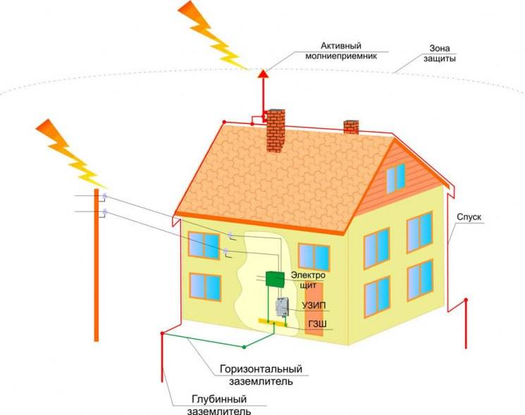
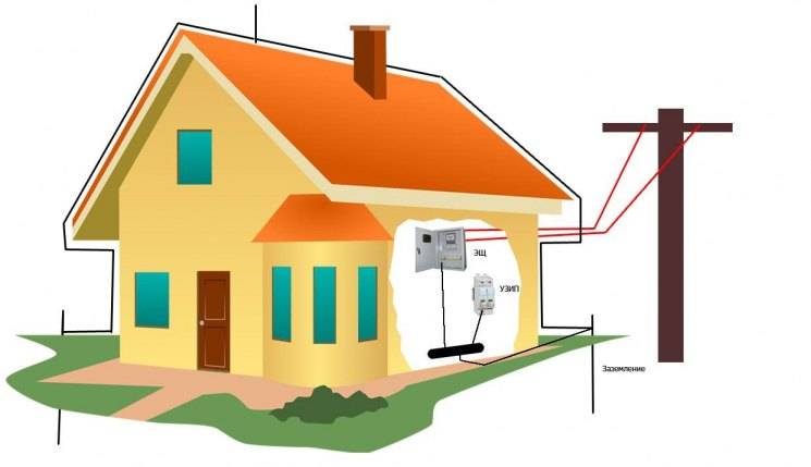
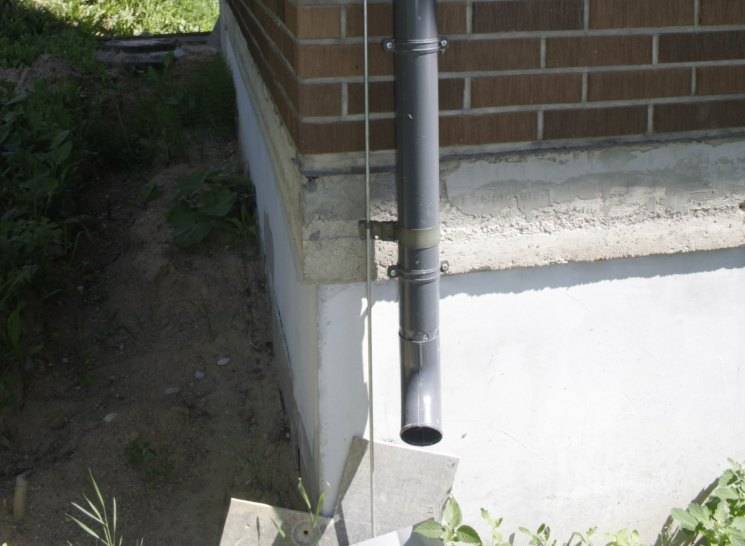
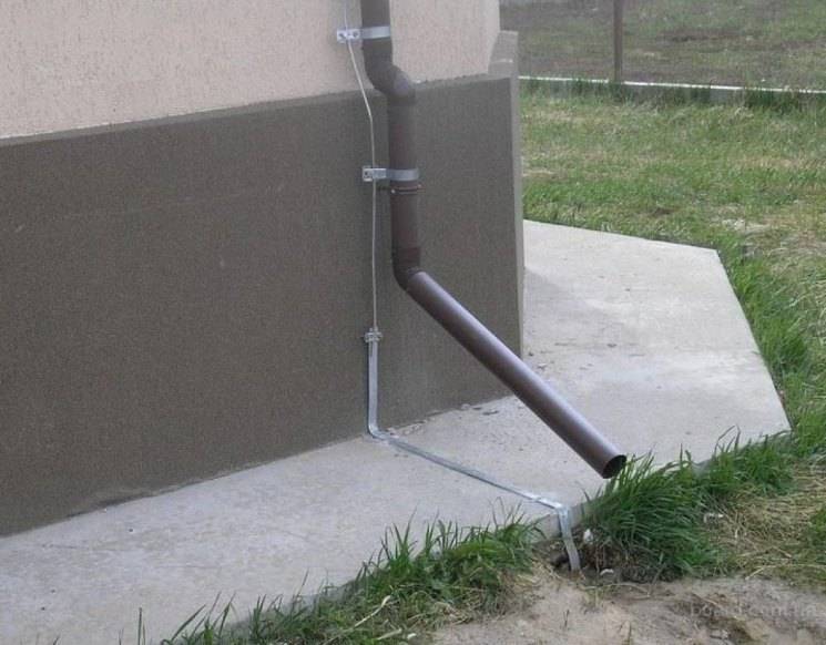
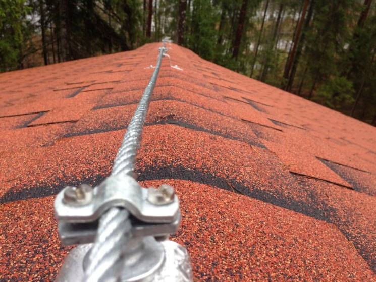
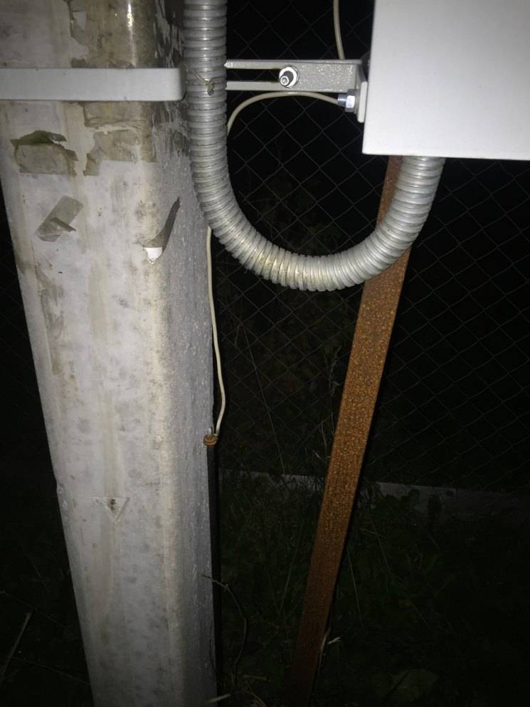
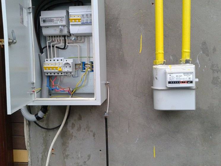
At the entrance to the house, a bolt is welded to the metal strip from the ground electrode, to which a copper conductor in insulation is attached (traditionally, the color of the ground wires is yellow with a green stripe) with a core cross section of at least 4 mm2.
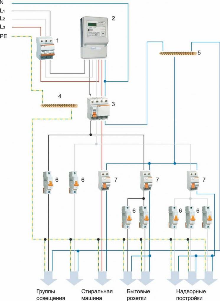
Ground loop PUE norms
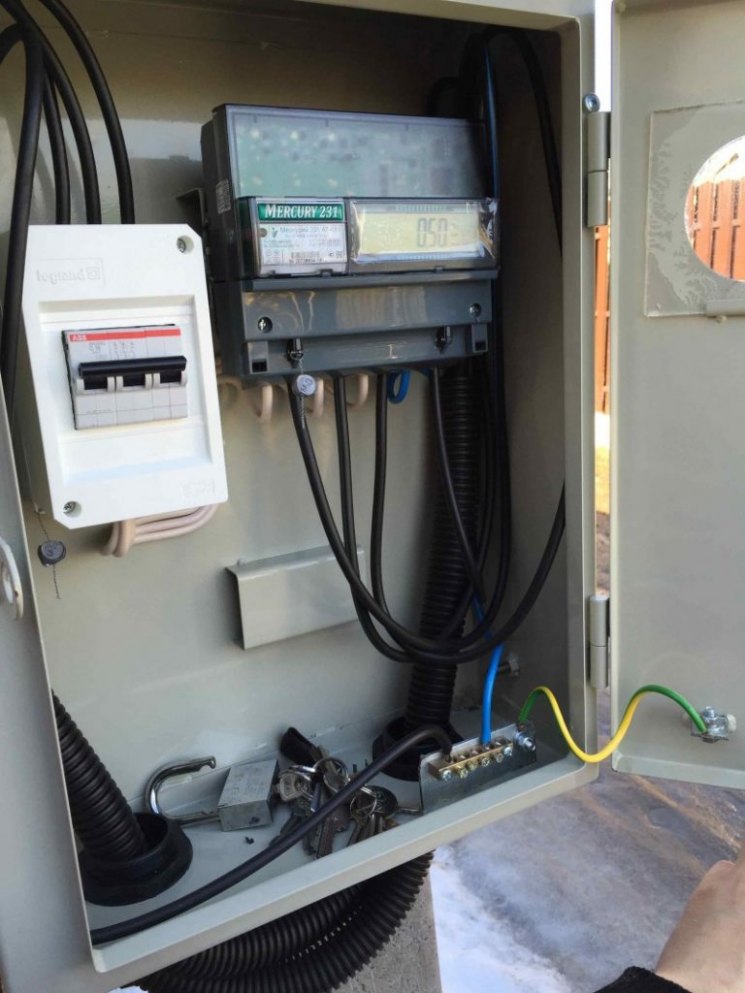
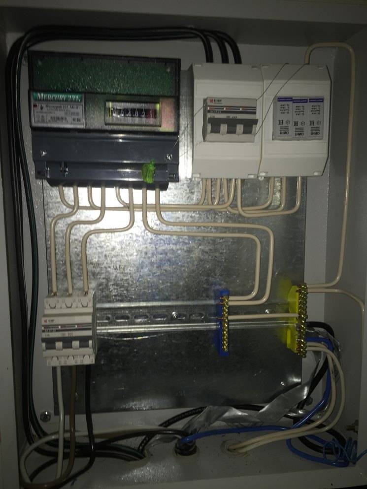
In the electrical panel, grounding is connected to a special bus. Moreover, only on a special platform, polished to a shine and lubricated with grease. From this bus, the "ground" is connected to each line that is bred around the house.Moreover, the wiring of the "ground" with a separate conductor according to the rules of the PUE is unacceptable - only as part of a common cable. This means that if your wiring is wired with two-wire wires, you will have to completely change it.
Grounding installation
- First, we prepare vertical ground electrodes. We cut them with a grinder in accordance with the calculated data. Then we grind the ends of the pins under the cone. This is done so that the electrode enters the ground more easily.
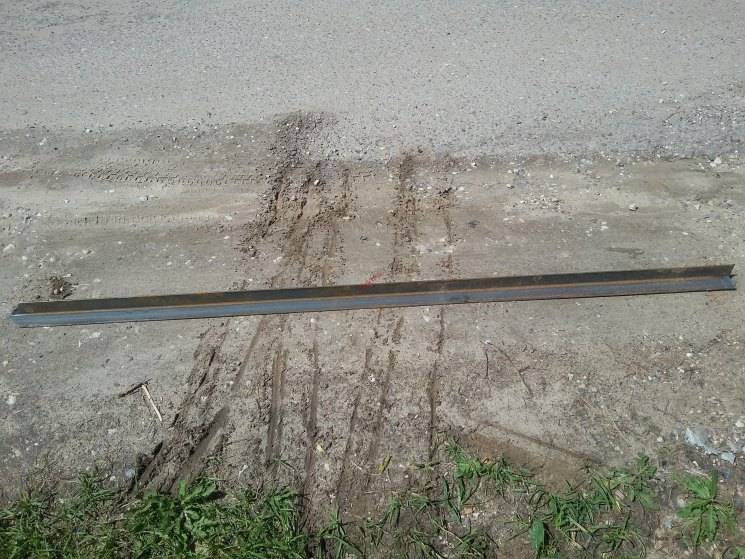
- Then we cut the steel strip. The length of each segment should be slightly longer than the side of the triangle (about 20–30 centimeters). It is advisable to bend the ends of the strips in advance with pliers for tight contact with the pins during welding.
- We take the prepared pins and hammer them into the vertices of the triangle. If the ground is sandy and the electrodes go in easily, then you can get by with a sledgehammer. But if the soil density is high or stones often come across, then you will have to use a powerful hammer drill or even drill wells. We hammer the rods so that they protrude above the base of the trench by about 20-30 centimeters.
- Next, we take a metal strip 40 × 5 millimeters and grab it by welding to the pins. As a result, you will get a contour in the form of an equilateral triangle.
- Now we make a contour approach to the building. For this we also use the strip. It must be taken out and fixed against the wall (if possible, near the switchboard).
Test work for performance
After the installation work is completed, a mandatory check is carried out. To do this, a light bulb is connected to one end of the circuit. The contour is made correctly if the lamp shines brightly. Also, the performance is checked using a factory device - a multimeter.
Why you can not make separate grounding
Redoing the wiring throughout the house, of course, is long and expensive, but if you want to operate modern electrical appliances and household appliances without any problems, this is necessary. Separate grounding of certain outlets is inefficient and even dangerous. And that's why. The presence of two or more such devices sooner or later leads to the output of the equipment included in these sockets.
The thing is that the resistance of the contours depends on the condition of the soil in each particular place. In some situation, a potential difference occurs between two grounding devices, which leads to equipment failure or electrical injury.
How to do the installation of the ground loop yourself?
When making a grounding device with your own hands, installing a circuit, it is necessary to develop a diagram, sketch, drawing. Next, choose a place and mark the site. You will need a tape measure of sufficient length. Next, earthworks are carried out and the structure is assembled. After that, it is buried, mounted, and then connected to the shield. Then the internal circuit (wiring around the house) is connected and tested using special electrical measuring instruments. The system does not require additional maintenance. It will last for decades if done right.
Choose a place
The shield is better to put in a special room. Usually this is a pantry, boiler room or closet.
It is important to exclude free access to children. The giving contour is placed at a distance from the perimeter of the building at least a meter
The maximum distance is 10 m. It is good when this is a place where people are not without special need. At the moment when the device extinguishes the current leakage, it is better if no one is there.Usually it is behind the house, in the territory of fenced beds, under decorative artificial plantings, alpine hills, etc.
Excavation
First you need to mark the site if a linear grounding scheme is used. Pegs are placed in places where the electrodes will be driven in. Now connect them with straight lines, pull the cord, which will serve as a guide for digging a trench. Its depth is from 30 to 50 centimeters. The width is about the same. The soil does not need to be removed. It will be required at the final stage of installation work before connecting the internal circuit. Waterproofing, filling is not required.
Assembling the structure
When the ground work is completed, it remains only to properly mount the circuit. Pull out the pegs and drive in the pins so that their ends protrude by 15-20 cm. The metal ties are cut to size. It makes sense to re-measure the distance between the pins. Control measurement will eliminate the error factor. Connections are welded by gas or electric welding. Now you can bury the trench, but only except for the entry point into the house, since it also needs to be made, attached, connected to the switchboard.
Entering the house
As a tire, materials are used, the properties of which are described earlier. The main thing is to securely fasten it to the contour. Now lead the other end through the wall to the control room. Make a hole in advance in the manner of a terminal so that bolting can be applied. When this work is completed, bury the last section of the trench and connect a bus splitter or a suitable core to the input. At this stage, it all depends on the type of grounding system of a private house chosen.
Check and control
After connecting the ground to the shield, you need to make sure that everything is done correctly.The control consists in checking the integrity of the circuits and the conductive capacity. By the way, if you want the circuit to work for sure, do not rush to dig in the trench at the previous stages. If a gap is detected, you will have to re-expose the metal structure and fix the problem. Or check the integrity in advance. But even after that, when the entire circuit is connected, it is necessary to double-check its performance.
Take a lamp with a power of 100-150 watts. They are screwed into the cartridge, from which small wires depart. This will be the so-called "control". One wire is thrown on the phase, the other on the ground. If the installation is done correctly, the light will be bright. Flickering, faint light, interruption or lack of current indicates a problem. If the light is dim, check the connections, clean the contacts, tighten the bolts. Observe safety precautions. Do not carry out repairs without de-energizing the building.
DIY grounding device: step-by-step instructions
If you are wondering: “how to make grounding in the country?”, then the following tool will be required to complete this process:
- welding machine or inverter for welding rolled metal and outputting the circuit to the foundation of the building;
- angle grinder (grinder) for cutting metal into specified pieces;
- nut plugs for bolts with M12 or M14 nuts;
- bayonet and pick-up shovels for digging and digging trenches;
- a sledgehammer for driving electrodes into the ground;
- perforator for breaking stones that can be encountered when digging trenches.
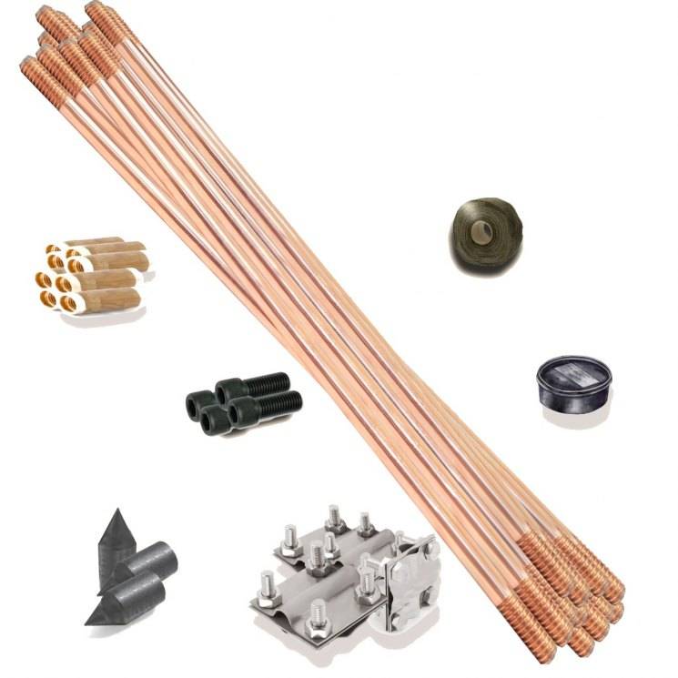
In order to properly and in accordance with regulatory requirements to perform a ground loop in a private house, we need the following materials:
- Corner 50x50x5 - 9 m (3 segments of 3 meters each).
- Steel strip 40x4 (metal thickness 4 mm and product width 40 mm) - 12 m in case of one point of the ground electrode to the building foundation. If you want to make a ground loop throughout the foundation, add the total perimeter of the building to the specified amount and also take a margin for trimming.
- Bolt M12 (M14) with 2 washers and 2 nuts.
- Copper grounding. A grounding conductor of a 3-core cable or a PV-3 wire with a cross section of 6–10 mm² can be used.
After all the necessary materials and tools are available, you can proceed directly to the installation work, which is described in detail in the following chapters.
Choosing a place for mounting the ground loop
In most cases, it is recommended to mount the ground loop at a distance of 1 m from the foundation of the building in a place where it will be hidden from the human eye and which will be difficult for both people and animals to reach.
Such measures are necessary so that if the insulation in the wiring is damaged, the potential will go to the ground loop and step voltage may occur, which can lead to electrical injury.
Excavation work
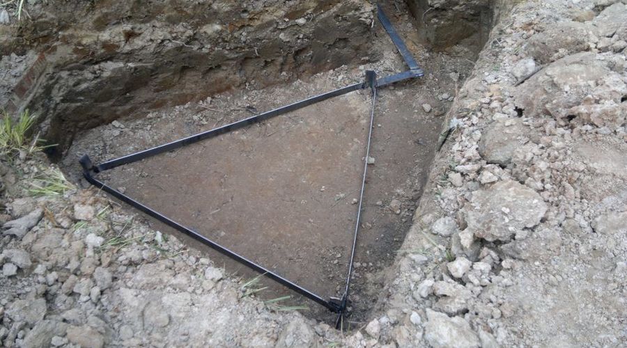
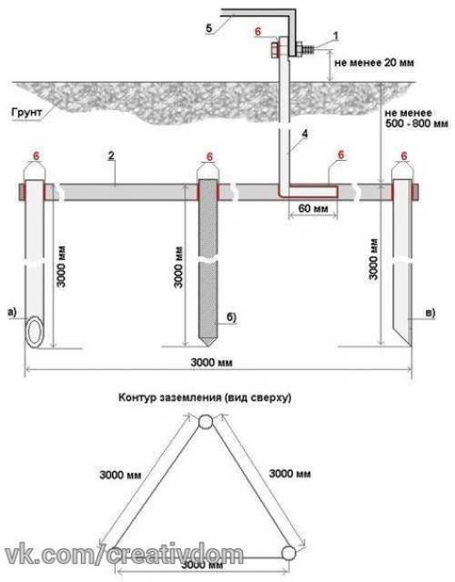
After a place has been chosen, markings have been made (under a triangle with sides of 3 m), the place for the strip with bolts to be placed on the foundation of the building has been determined, earthworks can begin.
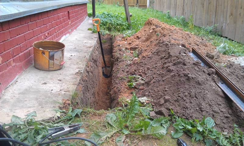
To do this, it is necessary to remove a layer of earth of 30-50 cm along the perimeter of the marked triangle with sides of 3 m using a bayonet shovel.This is necessary in order to subsequently weld strip metal to the ground electrodes without any special difficulties.


It is also worth additionally digging a trench of the same depth to bring the strip to the building and bring it to the facade.
Clogging of ground electrodes
After preparing the trench, you can proceed with the installation of the electrodes of the ground loop. To do this, first with the help of a grinder, it is necessary to sharpen the edges of a corner 50x50x5 or round steel with a diameter of 16 (18) mm².
Next, put them at the vertices of the resulting triangle and use a sledgehammer to hammer into the ground to a depth of 3 m
It is also important that the upper parts of the ground electrodes (electrodes) are at the level of the excavated trench so that a strip can be welded to them
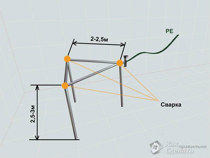
Welding
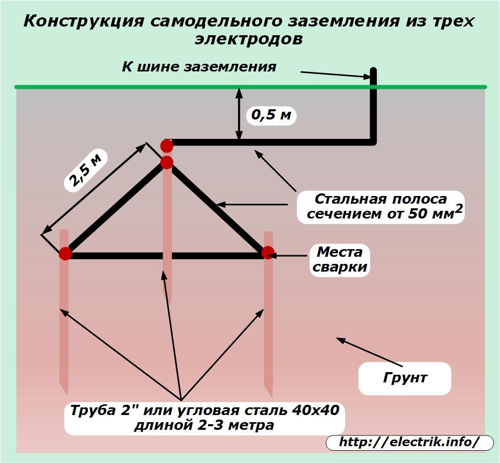
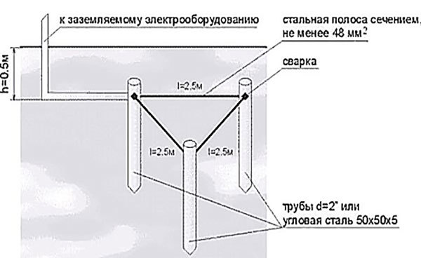
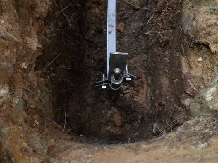
After the electrodes are hammered to the required depth using a 40x4 mm steel strip, it is necessary to weld the ground electrodes together and bring this strip to the foundation of the building where the ground conductor of the house, cottage or cottage will be connected.
Where the strip will go to the foundation at a height of 0.3–1 mot of the earth, it is necessary to weld the M12 (M14) bolt to which the house grounding will be connected in the future.
backfilling
After all welding work has been completed, the resulting trench can be filled up. However, before that, it is recommended to fill the trench with brine in the proportion of 2-3 packs of salt per bucket of water.
After the resulting soil must be well compacted.
Checking the ground loop
After completing all the installation work, the question arises "how to check the grounding in a private house?". For these purposes, of course, an ordinary multimeter is not suitable, since it has a very large error.
To perform this event, devices F4103-M1, Fluke 1630, 1620 ER pliers and so on are suitable.
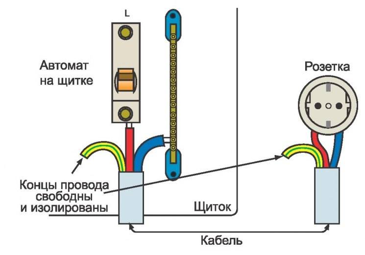
However, these devices are very expensive, and if you do the grounding in the country with your own hands, then an ordinary 150–200 W light bulb will be enough for you to check the circuit. For this test, you need to connect one terminal of the bulb holder to the phase wire (usually brown) and the other to the ground loop.
If the light bulb shines brightly, everything is fine and the ground loop is fully functional, but if the light bulb shines dimly or does not emit a luminous flux at all, then the circuit is mounted incorrectly and you need to either check the welded joints or mount additional electrodes (which happens with low electrical conductivity of the soil).
Touch voltage and step voltage
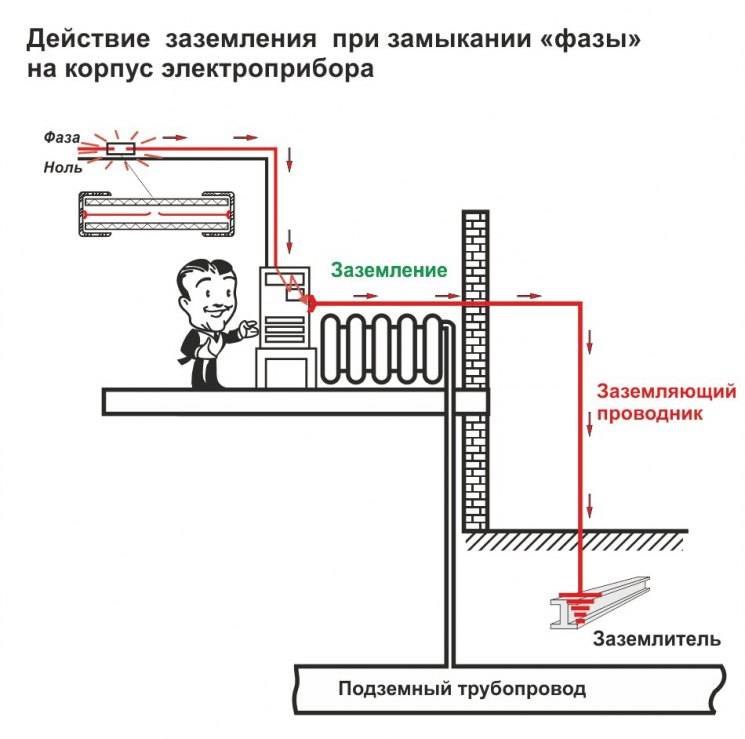
If a person touches the body of the electrical appliance considered in the example, it has more resistance than the part of the earth on which it stands, and the current through it is small. But it stands on the ground in the zone of spreading of the short circuit current. And this means that there is some tension between the contacting parts of the body. These are not always hands and feet, but considering this particular case is enough to understand the process. The voltage acting on a person through these points is the touch voltage.
There are certain rules for it. They strive to reduce it as much as possible, therefore, by calculation, acceptable parameters for the grounding device are achieved.
For simplicity, let's take only one ground electrode, consider what happens directly on the ground. The greater the distance from the ground electrode, the lower the voltage, the potential relative to the remote point, where it is equal to 0. Directly at the ground electrode itself, it is the maximum possible.If you abstractly connect points with the same potential, so-called equipotential lines are formed - circles. Obviously, approaching the grounding conductor, which conducts a short circuit current, at some distance a person receives some voltage between the feet - the potential difference from the position of the feet. This is the stride voltage.
Of course, in electrical installations where the earth fault current tends to turn off this voltage as soon as possible, it is not too dangerous, even if it exists for some seconds, a person may get some discomfort, but that's all.
In other electrical installations, where the earth fault current can exist for a long time, special attention is also paid to this. By the way, step voltage is a term that is actively used in electrical safety in terms of approaching live parts that close to the ground in open and closed switchgears
And there is a valid approach distance to these devices - 4 m for closed and 8 for open. They are related to how the ground fault current flows through the ground.


The touch and step voltages tend to be minimal so that a person does not suffer. For this, norms were obtained, published in the PUE - for practical use.
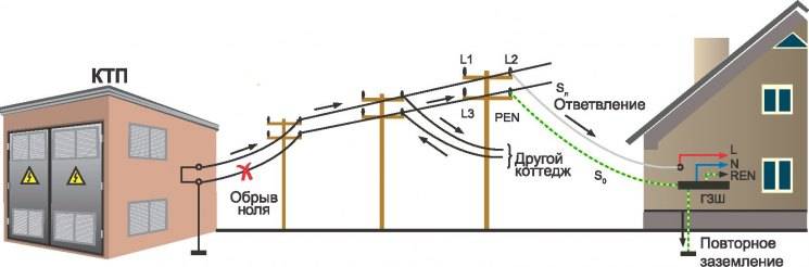
And when an overhead line departs from the substation, then after certain distances, to ensure a short-circuit current sufficient to trigger the protection, repeated grounding devices are arranged on the supports.
At the entrance to domestic buildings: houses, cottages, a ground loop is also arranged, which is also repeated.As soon as it is connected, it is impossible to measure its individual parameters - it becomes an integral part of the entire system.
Of course, the private trader is only interested in his "own" circuit, more precisely, how to make grounding in the house. So that it is effective, and forces and means are not wasted. the resistance value of the re-grounding device for a private house is the same as for everyone else. These are 15, 30, 60 ohms, respectively, for voltages of 660, 380, 220 V. of a three-phase current source or 380, 220, 127 V. of a single-phase current source
And it doesn’t matter that often it is a single-phase voltage of 220v - 30 ohms, when the circuit is not connected, 10 ohms for a grounding device connected to the network
However, it may turn out that under certain conditions the economic component of the calculated grounding exceeds reasonable limits. For example, soil resistivity is so high that even a multiple increase in the number of ground electrodes does not bring the desired result. Therefore, with a soil resistivity of more than 100 ohms per meter, the norm for a grounding device can be exceeded, but not more than 10 times.
Grounding schemes: which one is better to do
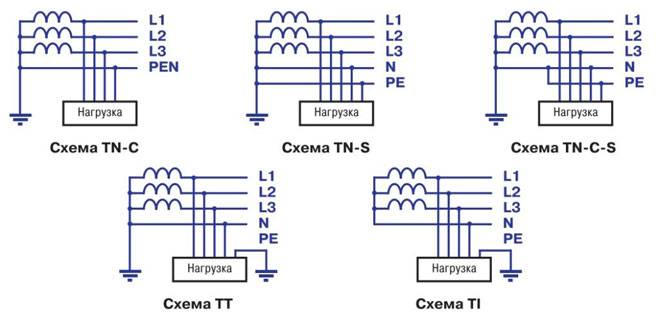
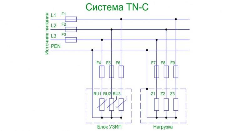
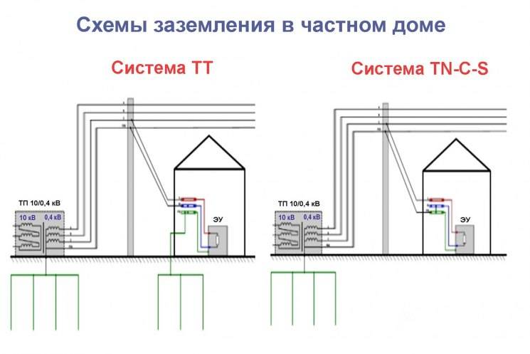
The grounding system of a private house depends on the type of network connection to it. Most often, it is performed according to the TN-C principle. Such a network is provided with a two-wire cable or a two-wire overhead line at a voltage of 220 V and a four-wire cable or a four-wire line at 380 V. In other words, the phase (L) and the combined protective-neutral wire (PEN) are suitable for the house. In full-fledged, modern networks, the PEN conductor is divided into separate wires - working or zero (N) and protective (PE), and the supply is carried out by a three-wire or five-wire line, respectively.Given these options, the grounding scheme can be of 2 varieties.
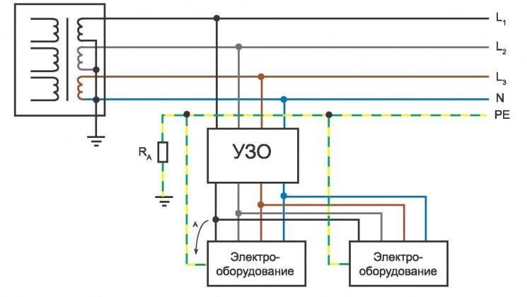
TN-C-S system
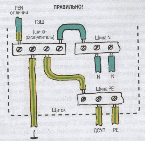
Provides for the division of the PEN-input into parallel conductors. To do this, in the introductory cabinet The PEN conductor is divided into 3 busbars: N ("neutral"), PE ("ground") and bus-splitter for 4 connections. Further, the conductors N and PE cannot contact each other. The PE busbar is connected to the cabinet body, and the N-conductor is installed on the insulators. The ground loop is connected to the splitter bus. A jumper with a cross section of at least 10 sq. mm (for copper) is installed between the N-conductor and the ground electrode. In further wiring, "neutral" and "ground" do not intersect.
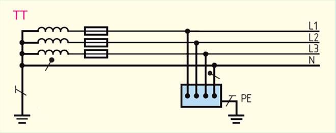
TT system
In such a circuit, it is not required to split the conductors, because. the neutral and earth conductor are already separated in a suitable network. In the cabinet, the correct connection is simply made. The ground loop is connected to the (core) PE wire.
The question of which grounding system is better does not have a clear answer. The CT circuit is easier to install and does not require additional protective devices. However, the vast majority of networks operate on the TN-C principle, which forces the use of the TN-C-S scheme. In addition, electrical installations with two-wire power are often used in everyday life. When grounding the CT, the case of such devices is energized if the insulation is damaged. In this case, the TN-C-S grounding is much more reliable.
Let's take a look at the theory
Let's consider an example - a grounding circuit with a single vertical ground electrode driven into the ground. The metal case of the electrical appliance is connected to it, where a short circuit occurred - the phase connected to the case.In this case, the initial conditions are: “metal-to-metal” short circuit, without taking into account external factors, so the resistance at the contact point can be neglected. The resistance of the grounding conductor from the device to the ground is also not taken into account, since it is insignificant when a sufficiently large cross section is used.
Further, provided that the soil around the ground electrode is considered homogeneous in all directions, then the current will go into the ground equally in the same directions. In this case, the highest current density will be at the ground electrode itself. The farther from the ground electrode, the more its density decreases. As a result, it turns out that on the path of the current, the resistance to its movement decreases more and more with increasing distance from the ground electrode, because it passes through an ever-increasing "section" of the conductor - the earth. And the voltage that decreases along the path of this current according to Ohm's law: the largest is on the ground electrode itself, and gradually decreases as it moves away. And at some distance from the ground electrode, the voltage will become negligible - it will approach 0. A point with such a voltage is a point of zero potential. In fact, this point of zero potential is the very ground with which the body of the electrical appliance is connected.
The resistance of the grounding device is not the electrical resistance of its metal - it is low, it is not the resistance between the metal of the pin and the ground - under certain conditions it is also small. This is the earth resistance between the pin and the zero potential point.
All this is displayed by the formula Rz: Uf / Ikz. That is, the resistance of the grounding device will be equal to the phase voltage that came to the case, divided by the short-circuit current. Everything is tied to this formula.
But the resistance parameters of a single ground electrode will most likely not be enough to organize a ground loop that meets the requirements of the PUE. How to bring everything in line? The area of the ground electrode is critical, so the most obvious solution is to hammer in another electrode nearby. But if you hammer them in close proximity, then the current spreads, as before, nothing changes. In order to change the spreading configuration, it is necessary to space the ground electrodes away from each other. In this case, the division of current between them is obtained - it flows from each of them.


However, there is a zone where they intersect. It turns out that this is not a simple parallel connection of two resistances, except in cases where the ground electrodes are very far apart. But this is very impractical, for a real grounding device, huge areas will be required. Therefore, when calculating the removal of ground electrodes, correction factors are used that take into account their mutual influence - the shielding factor.
To further reduce the resistance of the ground loop, you need to increase the depth of the electrode, that is, increase its length. After all, the longer the ground electrode, the larger the area that contributes to the spreading of current. This effect is widely used in the manufacture of copper-plated pins for grounding kits. They are hammered into the ground one after another, connected by threaded couplings into a single electrode. In this case, the depth required for the grounding parameters is achieved.
By connecting the ground electrodes with a horizontal connection, the total resistance of the grounding device is further reduced.
The influence of the connection is also taken into account, it is also taken into account that it is shielded by vertical electrodes
It turns out a system of several elements that depend on each other:
Distance between vertical ground electrodes.
Their number.
What matters is how deep they are.
Form - rod, pipe, corner. This is a different area of \u200b\u200badjacent to the ground.
The shape and length of the horizontal connection .. That is, there are a lot of factors and it is incorrect to calculate everything using one formula
The remaining parameters for calculation are taken from the following concepts and quantities
That is, there are a lot of factors and it is incorrect to calculate everything using one formula. The remaining parameters for the calculation are taken from the following concepts and quantities.
The role of grounding
Electricity was discovered more than two hundred years ago. During this time, it has not only taken root in our society, but has become an absolutely indispensable part of it.
Technological progress in the last 20-30 years has developed incredibly rapidly, resulting in a huge number of electrical appliances and devices that are either necessary in our lives or simply make it more comfortable.
The ground loop is needed so that all these electrical utensils work normally and are not an immediate source of danger.
If the network is done correctly, when such problems occur, the residual current device is triggered.
Conventional electrical devices should not create such problems. Serious malfunctions in the electrical circuit of the house are usually associated with large household appliances - refrigerators, washing machines, microwaves, ovens, and so on.
Roughly speaking, this category includes equipment that can use more than 500 watts in operation.
If banal lamps can easily get by with protection inside the outlet, which is not always there, then for large household appliances, direct connection to the ground line is usually a better option.
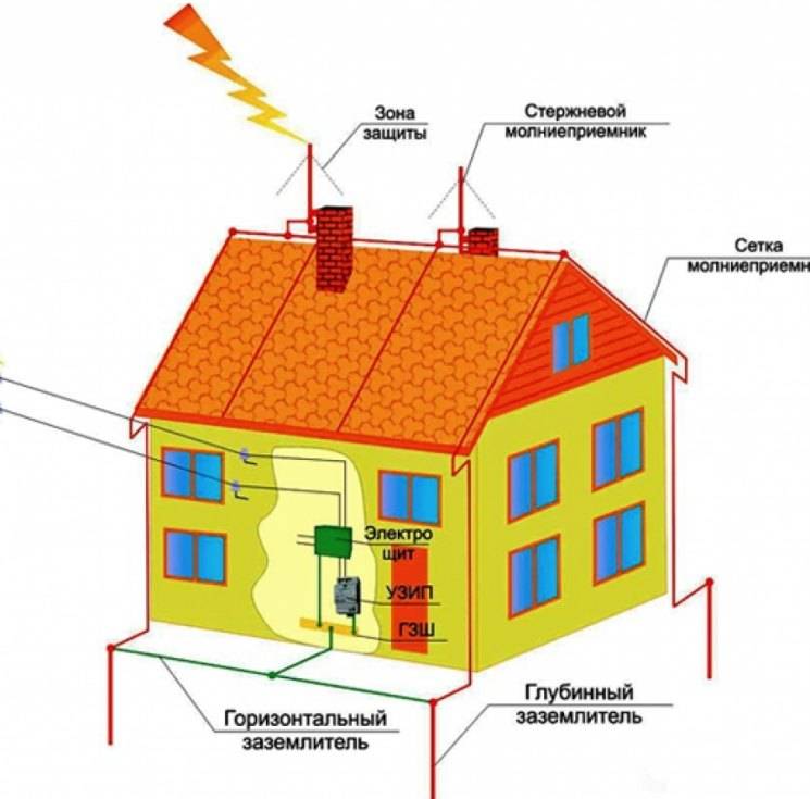
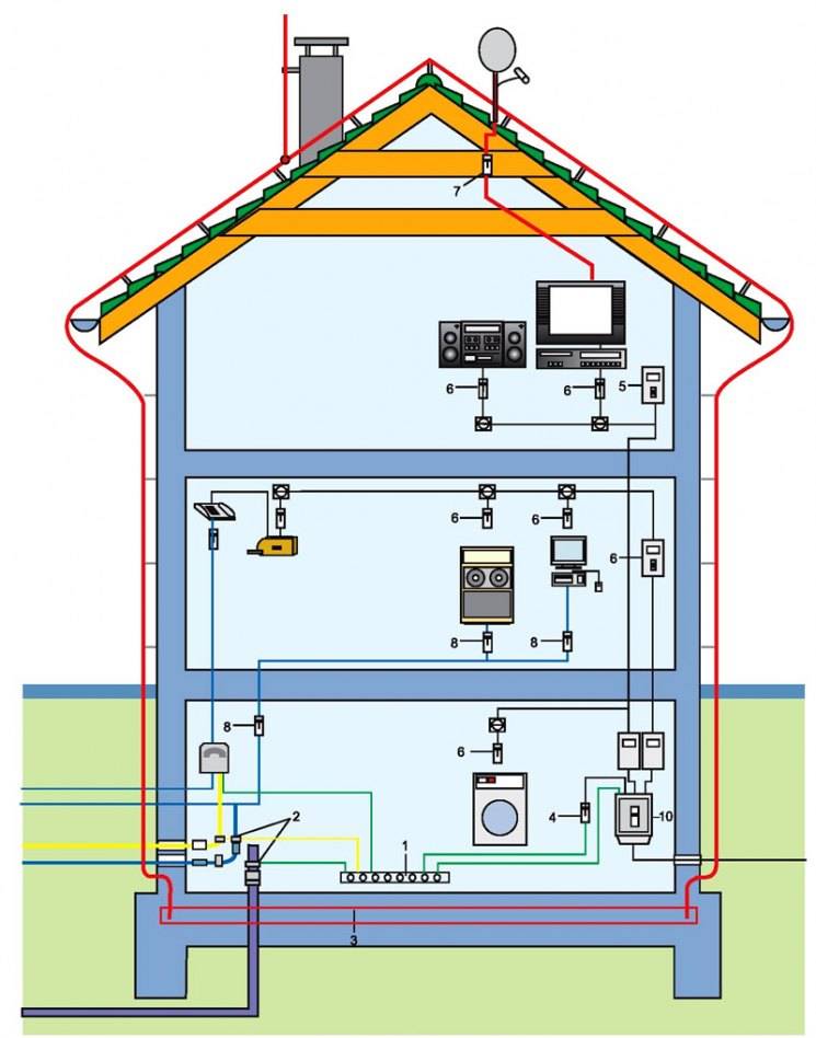
If you look at the photo of grounding in a private house, you will notice that it must pass through all floors and have access to all necessary electrical devices.
That is why electricians recommend running a separate ground line to all rooms in the house, in case there are devices in them that need it.
A simple example is the microwave. Microwaves are now in almost all homes. The device is quite simple, but it makes life much more convenient and comfortable, and its price is quite affordable, depending on the model and manufacturer.


At the initial power, no one usually uses a microwave, but few people know that it belongs to a technique that needs to be grounded.
What for? If you do not make a banal grounding with your own hands for a microwave, during operation it will create a rather strong background, which negatively affects the health of others - people, animals, plants.
Some may have noticed that indoor plants grow extremely poorly next to a microwave that does not have grounding.
Another example is a washing machine. They are also found in every home and also have a large electricity consumption.
After reading the instructions for the washing machine, people usually immediately begin to think about how to make grounding.Those who do not read the instructions and do not ground, after a while begin to notice that if you touch it with a wet hand while the washing machine is running, you feel a slight penetration of electricity.

In addition to such discomfort, there may also be problems inside the machine itself, eventually leading to a breakdown, which you will already pay for.
Computers should also be connected to at least grounded outlets. A technically complex ecosystem of parts runs inside the computer case, and often all this happens with a large consumption of electricity.

4 Installation of grounding parts - circuit definition and assembly
Before starting work, we determine the scheme. There are quite a few of them, but the most common are two: closed and linear. Each option requires approximately the same consumption of materials, it's all about reliability.
A closed circuit is most often performed as a triangle, although it may have a different look. It is reliable in its operation. If one jumper between the pins is damaged, it continues to work. For a private house, it is recommended to use a closed circuit - a triangle.
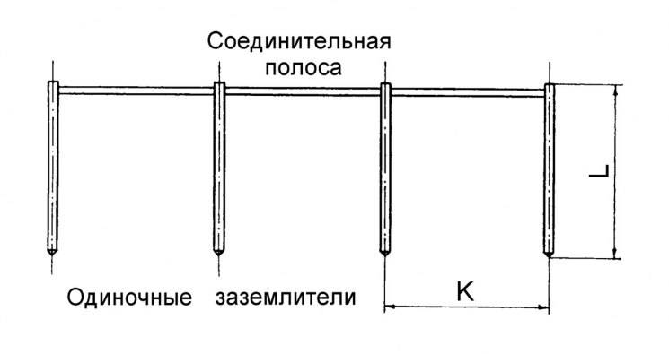
With the linear method, all the rods are arranged in a line, connected in series. The disadvantage is that damage to one jumper reduces efficiency, and if it is the first, then performance is completely lost.
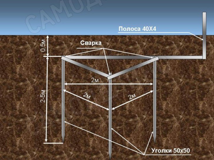
To create a ground loop, you need to drive three pins vertically into the ground and connect them with ground electrodes located horizontally. In addition, a metal bar or tape should be connected from the grounding conductor to connect to the electrical panel. We make vertical ground electrodes from steel angles 50×50×5 mm, horizontal - from steel strips 40×4 mm.We connect the circuit and the inlet shield with a bar of at least 8 mm2. You can use other materials, which are described above, but we will show the manufacture using these materials as an example.
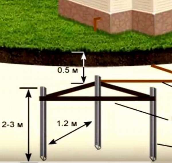
Stepping back from the foundation about one meter, we mark a triangle with sides of 1.2 m. We dig a trench along the marking lines to a depth of 1 m. We make the width sufficient to engage in welding work. This is a trench for horizontal ground lines.

We cut the ends of the squares with a grinder at an acute angle to make it easier to score. We install them at the vertices of the triangle and beat them with a sledgehammer. They go quite easily, and after a few minutes the first one is ready, we do the same with the other two. If there is a drill, you can drill a well to clog less. Above the lower level of the trench, the rods should protrude by 30 centimeters.
When they are all in the ground, proceed to connect with horizontal stripes to create a closed loop. Using conventional welding, we weld the strips to the corners. We use welding, because the bolted connection in the ground will quickly collapse. Loss of contact will cause the ground to lose its functionality.


If there is no way to use welding, bolts can be used, but only above the ground surface. They are treated with conductive grease, periodically tightened and lubricated again.
The assembled circuit is connected to the shield. We weld steel wire to the corner, lay along the bottom of the trench to the electrical panel. At the other end, we weld a washer to create a reliable contact at the junction with the VSC. If there is no rod of a suitable section, we use the same strip as for horizontal jumpers.It is even preferable, it has a large contact area with the ground, but it is more difficult to work with it. In extreme cases, if it is not possible to bend the strip at the desired angle, we cut it into pieces and weld it from separate elements.
Grounding calculation, formulas and examples
Even if the assembly process seems simple, difficulties may arise in the calculations. The main requirement is that the conductors withstand the voltage surge, and the electrodes have sufficient parameters to freely “transmit” it to the ground. It's good when there is a neighbor who has already done similar work and had the opportunity to test the effectiveness of the system in action. Otherwise, you will have to do everything yourself.
Ground resistance
For each bar, the following formula is used:
Here:
- ρ equiv - equivalent to the resistivity of homogeneous soils (determined according to the table for specific types of soils);
- L is the length of the electrode (m);
- d is the diameter of the rod (m);
- T is the distance from the middle of the pin to the surface (m).
| Soil type | Soil resistivity (equivalent), Ohm*m |
| Peat | 20 |
| Chernozemny | 50 |
| Clayey | 60 |
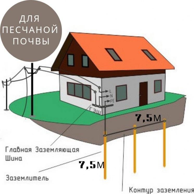
| sandy loam | 150 |
| Sandy (groundwater occurrence up to 5 m) | 500 |
| Sandy (groundwater occurrence more than 5m) | 1000 |
Dimensions and distances for earth electrodes
To do this, you need to know the permissible total resistance of the circuits (for a network of 127-220 V - 60 Ohms, for 380 V - 15 Ohms). The value of the climate coefficient is taken from the table below.
| Type of electrode, type of placement | Climate zone | |||
| First | Second | Third | Fourth | |
| Rod placed vertically | 1,8 / 2,0 | 1,5 / 1,8 | 1,4 / 1,6 | 1,2 / 1,4 |
| Strip lying horizontally | 4,5 / 7 | 3,5 / 4,5 | 2,0 /2,5 | 1,5 |
Now you need to take the soil resistance, which is calculated using the formula from the previous section of the article. It is multiplied by the climate coefficient.The resulting value is divided by the total resistance of the circuit (see above). The result will be the number of electrodes. Round up if necessary.


