- Common breakdowns
- How to choose and buy a circulation pump
- Choose a circulation pump
- Buy circulation pump
- Calculation of heat losses
- Why do you need to calculate
- Head height calculation
- How to work in EXCEL
- Entering initial data
- Formulas and Algorithms
- Registration of results
- Example from Alexander Vorobyov
- The main types of pumps for heating
- Wet equipment
- "Dry" variety of devices
- cavitation
- Calculation of the number of radiators for water heating
- Calculation formula
- Characteristics of radiators
- Types of heating systems
- How to calculate the power of a gas heating boiler for the area of \u200b\u200bthe house?
- How to calculate the power of the heating boiler by the volume of the house?
- How to calculate the power of a boiler with a hot water circuit?
- What is the best way to calculate - by area or by volume?
- How much is the "extra" kilowatt?
- We also recommend seeing:
- A few extra tips
- Conclusion
- Number of speeds
- Calculation of the pump for the heating system
Common breakdowns
The most common problem due to which the equipment that provides forced pumping of the coolant fails is its long downtime.
Most often, the heating system is actively used in winter, and is turned off in the warm season. But since the water in it is not clean, over time, sediment will form in the pipes.Due to the accumulation of hardness salts between the impeller and the pump, the unit stops working and may fail.
The above problem is easily solved. To do this, you need to try to start the equipment yourself by unscrewing the nut and manually turning the pump shaft. Often this action is more than enough.
If the device still does not start, then the only way out is to dismantle the rotor and then thoroughly clean the pump from the accumulated salt sediment.
How to choose and buy a circulation pump
Circulation pumps face somewhat specific tasks, different from water, borehole, drainage, etc. If the latter are designed to move liquid with a specific spout point, then circulation and recirculation pumps simply “drive” the liquid in a circle.
I would like to approach the selection somewhat non-trivially and offer several options. So to speak, from simple to complex - start with the recommendations of manufacturers and the last to describe how to calculate a circulation pump for heating using formulas.
Choose a circulation pump
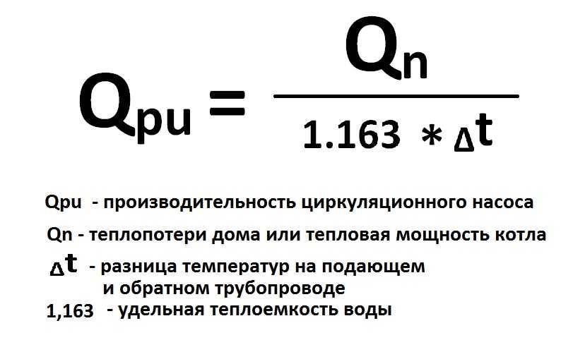
This easy way to choose a circulation pump for heating was recommended by one of the sales managers of WILO pumps.
It is assumed that the heat loss of the room per 1 sq. m. will be 100 watts. Formula for calculating the flow:
Total heat loss at home (kW) x 0.044 \u003d circulation pump consumption (m3/hour)
For example, if the area of a private house is 800 sq. m. the required flow will be:
(800 x 100) / 1000 \u003d 80 kW - heat loss at home
80 x 0.044 \u003d 3.52 cubic meters / hour - the required flow rate of the circulation pump at a room temperature of 20 degrees. FROM.
From the WILO range, TOP-RL 25/7.5, STAR-RS 25/7, STAR-RS 25/8 pumps are suitable for such requirements.
Regarding pressure. If the system is designed in accordance with modern requirements (plastic pipes, a closed heating system) and there are no non-standard solutions, such as a high number of storeys or a long length of heating pipelines, then the pressure of the above pumps should be enough "to the head".
Again, such a selection of a circulation pump is approximate, although in most cases it will satisfy the required parameters.
Select a circulation pump according to the formulas.
If there is a desire before buying a circulation pump to understand the required parameters and select it according to the formulas, then the following information will come in handy.
determine the required pump pressure
H=(R x L x k) / 100, where
H is the required pump head, m
L is the length of the pipeline between the most remote points "there" and "back". In other words, this is the length of the largest "ring" from the circulation pump in the heating system. (m)
An example of calculating a circulation pump using formulas
There is a three-storey house measuring 12m x 15m. Floor height 3 m. The house is heated by radiators ( ∆ T=20°C) with thermostatic heads. Let's calculate:
required heat output
N (ot. pl) \u003d 0.1 (kW / sq.m.) x 12 (m) x 15 (m) x 3 floors \u003d 54 kW
calculate the flow rate of the circulation pump
Q \u003d (0.86 x 54) / 20 \u003d 2.33 cubic meters / hour
calculate the pump head
The manufacturer of plastic pipes, TECE, recommends the use of pipes with a diameter at which the fluid flow rate is 0.55-0.75 m / s, the resistivity of the pipe wall is 100-250 Pa / m.In our case, a pipe with a diameter of 40mm (11/4″) can be used for the heating system. At a flow rate of 2.319 cubic meters per hour, the coolant flow rate will be 0.75 m / s, the specific resistance of one meter of the pipe wall is 181 Pa / m (0.02 m of water column).
WILO YONOS PICO 25/1-8
GRUNDFOS UPS 25-70
Almost all manufacturers, including such "grands" as WILO and GRUNDFOS, place on their websites special programs for selecting a circulation pump. For the aforementioned companies, these are WILO SELECT and GRUNDFOS WebCam.
The programs are very convenient and easy to use.
Particular attention should be paid to the correct entry of values, which often causes difficulties for untrained users.
Buy circulation pump
When buying a circulation pump, special attention should be paid to the seller. Currently, a lot of counterfeit products are “walking” on the Ukrainian market. How can one explain that the retail price of a circulation pump on the market can be 3-4 times less than that of a manufacturer's representative?
How can one explain that the retail price of a circulation pump on the market can be 3-4 times less than that of a manufacturer's representative?
According to analysts, the circulation pump in the domestic sector is the leader in energy consumption. In recent years, companies have been offering very interesting new products - energy-saving circulation pumps with automatic power control. From the household series, WILO has YONOS PICO, GRUNDFOS has ALFA2. Such pumps consume electricity by several orders of magnitude less and significantly save the owners' money costs.


Calculation of heat losses
The first stage of the calculation is to calculate the heat loss of the room.The ceiling, the floor, the number of windows, the material from which the walls are made, the presence of an interior or front door - all these are sources of heat loss.
Consider the example of a corner room with a volume of 24.3 cubic meters. m.:
- room area - 18 sq. m. (6 m x 3 m)
- 1st floor
- ceiling height 2.75 m,
- external walls - 2 pcs. from a bar (thickness 18 cm), sheathed from the inside with gypsum board and pasted over with wallpaper,
- window - 2 pcs., 1.6 m x 1.1 m each
- floor - wooden insulated, below - subfloor.
Surface area calculations:
- external walls minus windows: S1 = (6 + 3) x 2.7 - 2 × 1.1 × 1.6 = 20.78 sq. m.
- windows: S2 \u003d 2 × 1.1 × 1.6 \u003d 3.52 sq. m.
- floor: S3 = 6×3=18 sq. m.
- ceiling: S4 = 6×3= 18 sq. m.
Now, having all the calculations of heat-releasing areas, we estimate the heat loss of each:
- Q1 \u003d S1 x 62 \u003d 20.78 × 62 \u003d 1289 W
- Q2= S2 x 135 = 3x135 = 405W
- Q3=S3 x 35 = 18×35 = 630W
- Q4 = S4 x 27 = 18x27 = 486W
- Q5=Q+ Q2+Q3+Q4=2810W
Why do you need to calculate
The circulation pump installed in the heating system must effectively solve two main tasks:
- create in the pipeline such a liquid pressure that will be able to overcome the hydraulic resistance in the elements of the heating system;
- ensure the constant movement of the required amount of coolant through all elements of the heating system.
When performing such a calculation, two main parameters are taken into account:
- the total need of the building for thermal energy;
- the total hydraulic resistance of all elements of the heating system being created.
Table 1. Thermal power for various rooms
After determining these parameters, it is already possible to calculate the centrifugal pump and, based on the values obtained, select a circulation pump with the appropriate technical characteristics.The pump selected in this way will not only provide the required pressure of the coolant and its constant circulation, but also work without excessive loads, which can cause the device to fail quickly.
Head height calculation
At the moment, the main data for the selection of a circulation pump have been calculated, then it is necessary to calculate the pressure of the coolant, this is necessary for the successful operation of all equipment. This can be done like this: Hpu=R*L*ZF/1000. Parameters:
- Hpu is the power or head of the pump, which is measured in meters;
- R is denoted as the loss in the supply pipes, Pa / M;
- L is the length of the contour of the heated room, measurements are taken in meters;
- ZF is used to represent the drag coefficient (hydraulic).
The diameter of the pipes can vary greatly, so the R parameter has a significant range from fifty to one hundred and fifty Pa per meter, for the place selected in the example, it is required to take into account the highest R indicator. from the size of the heated room. All indicators of the house are summed up, and then multiplied by 2. With a house area of three hundred meters squared, let's take, for example, a house length of thirty meters, a width of ten meters, and a height of two and a half meters. In this outcome: L \u003d (30 + 10 + 2.5) * 2, which is equal to 85 meters. The easiest coefficient. resistance ZF is determined as follows: in the presence of a thermo-static valve, it is equal to - 2.2 m, in the absence - 1.3. We take the biggest one. 150*85*2.2/10000=85 meters.
Read also:
How to work in EXCEL
The use of Excel spreadsheets is very convenient, since the results of the hydraulic calculation are always reduced to a tabular form. It is enough to determine the sequence of actions and prepare exact formulas.
Entering initial data
A cell is selected and a value is entered. All other information is simply taken into account.
| Cell | Value | Meaning, designation, unit of expression |
|---|---|---|
| D4 | 45,000 | Water consumption G in t/h |
| D5 | 95,0 | Inlet temperature tin in °C |
| D6 | 70,0 | Outlet temperature tout in °C |
| D7 | 100,0 | Inner diameter d, mm |
| D8 | 100,000 | Length, L in m |
| D9 | 1,000 | Equivalent pipe roughness ∆ in mm |
| D10 | 1,89 | The amount of odds local resistances - Σ(ξ) |
- the value in D9 is taken from the directory;
- the value in D10 characterizes the resistance at the welds.
Formulas and Algorithms
We select the cells and enter the algorithm, as well as the formulas of theoretical hydraulics.
| Cell | Algorithm | Formula | Result | Result value |
|---|---|---|---|---|
| D12 | !ERROR! D5 does not contain a number or expression | tav=(tin+tout)/2 | 82,5 | Average water temperature tav in °C |
| D13 | !ERROR! D12 does not contain a number or expression | n=0.0178/(1+0.0337*tav+0.000221*tav2) | 0,003368 | kinematic coefficient. water viscosity - n, cm2/s at tav |
| D14 | !ERROR! D12 does not contain a number or expression | ρ=(-0.003*tav2-0.1511*tav+1003, 1)/1000 | 0,970 | Average density of water ρ, t/m3 at tav |
| D15 | !ERROR! D4 does not contain a number or expression | G’=G*1000/(ρ*60) | 773,024 | Water consumption G’, l/min |
| D16 | !ERROR! D4 does not contain a number or expression | v=4*G:(ρ*π*(d:1000)2*3600) | 1,640 | Water speed v, m/s |
| D17 | !ERROR! D16 does not contain a number or expression | Re=v*d*10/n | 487001,4 | Reynolds number Re |
| D18 | !ERROR! Cell D17 does not exist | λ=64/Re at Re≤2320 λ=0.0000147*Re at 2320≤Re≤4000 λ=0.11*(68/Re+∆/d)0.25 at Re≥4000 | 0,035 | Hydraulic friction coefficient λ |
| D19 | !ERROR! Cell D18 does not exist | R=λ*v2*ρ*100/(2*9.81*d) | 0,004645 | Specific friction pressure loss R, kg/(cm2*m) |
| D20 | !ERROR! Cell D19 does not exist | dPtr=R*L | 0,464485 | Friction pressure loss dPtr, kg/cm2 |
| D21 | !ERROR! Cell D20 does not exist | dPtr=dPtr*9.81*10000 | 45565,9 | and Pa respectively D20 |
| D22 | !ERROR! D10 does not contain a number or expression | dPms=Σ(ξ)*v2*ρ/(2*9.81*10) | 0,025150 | Pressure loss in local resistances dPms in kg/cm2 |
| D23 | !ERROR! Cell D22 does not exist | dPtr \u003d dPms * 9.81 * 10000 | 2467,2 | and Pa respectively D22 |
| D24 | !ERROR! Cell D20 does not exist | dP=dPtr+dPms | 0,489634 | Estimated pressure loss dP, kg/cm2 |
| D25 | !ERROR! Cell D24 does not exist | dP=dP*9.81*10000 | 48033,1 | and Pa respectively D24 |
| D26 | !ERROR! Cell D25 does not exist | S=dP/G2 | 23,720 | Resistance characteristic S, Pa/(t/h)2 |
- the D15 value is recalculated in liters, so it is easier to perceive the flow rate;
- cell D16 - add formatting according to the condition: "If v does not fall in the range of 0.25 ... 1.5 m / s, then the background of the cell is red / the font is white."
For pipelines with a height difference between the inlet and outlet, static pressure is added to the results: 1 kg / cm2 per 10 m.
Registration of results
The author's color scheme carries a functional load:
- Light turquoise cells contain the original data - they can be changed.
- Pale green cells are input constants or data that is little subject to change.
- Yellow cells are auxiliary preliminary calculations.
- Light yellow cells are the results of calculations.
- Fonts:
- blue - initial data;
- black - intermediate/non-main results;
- red - the main and final results of the hydraulic calculation.
Results in Excel spreadsheet
Example from Alexander Vorobyov
An example of a simple hydraulic calculation in Excel for a horizontal pipeline section.
Initial data:
- pipe length 100 meters;
- ø108 mm;
- wall thickness 4 mm.
Table of results of calculation of local resistances
Complicating step by step calculations in Excel, you better master the theory and partially save on design work. Thanks to a competent approach, your heating system will become optimal in terms of costs and heat transfer.
The main types of pumps for heating
All equipment offered by manufacturers is divided into two large groups: "wet" or "dry" type pumps. Each type has its own advantages and disadvantages, which must be taken into account when choosing.
Wet equipment
Heating pumps, called "wet", differ from their counterparts in that their impeller and rotor are placed in a heat carrier. In this case, the electric motor is in a sealed box where moisture cannot get.
This option is an ideal solution for small country houses. Such devices are distinguished by their noiselessness and do not require thorough and frequent maintenance. In addition, they are easily repaired, adjusted and can be used with a stable or slightly changing level of water flow.
A distinctive feature of modern models of "wet" pumps is their ease of operation. Thanks to the presence of "smart" automation, you can increase productivity or switch the level of windings without any problems.
As for the disadvantages, the above category is characterized by low productivity. This minus is due to the impossibility of ensuring high tightness of the sleeve separating the heat carrier and the stator.
"Dry" variety of devices
This category of devices is characterized by the absence of direct contact of the rotor with the heated water it pumps. The entire working part of the equipment is separated from the electric motor by rubber protective rings.
The main feature of such heating equipment is high efficiency. But from this advantage follows a significant disadvantage in the form of high noise. The problem is solved by installing the unit in a separate room with good sound insulation.
When choosing, it is worth considering the fact that the “dry” type pump creates air turbulence, so small dust particles can rise, which will negatively affect the sealing elements and, accordingly, the tightness of the device.
Manufacturers solved this problem this way: when the equipment is operating, a thin water layer is created between the rubber rings. It performs the function of lubrication and prevents the destruction of sealing parts.
Devices, in turn, are divided into three subgroups:
- vertical;
- block;
- console.
The peculiarity of the first category is the vertical arrangement of the electric motor. Such equipment should be bought only if it is planned to pump a large amount of heat carrier. As for block pumps, they are installed on a flat concrete surface.
Block pumps are intended for use in industrial purposes, when large flow and pressure characteristics are required
Console devices are characterized by the location of the suction pipe on the outside of the cochlea, while the discharge pipe is located on the opposite side of the body.
cavitation
Cavitation is the formation of vapor bubbles in the thickness of a moving liquid with a decrease in hydrostatic pressure and the collapse of these bubbles in the thickness where the hydrostatic pressure increases.
In centrifugal pumps, cavitation occurs at the inlet edge of the impeller, at the location with the highest flow rate and lowest hydrostatic pressure. The collapse of a vapor bubble occurs during its complete condensation, while at the place of collapse there is a sharp increase in pressure up to hundreds of atmospheres. If at the moment of collapse the bubble was on the surface of the impeller or blade, then the blow falls on this surface, which causes metal erosion. The surface of the metal subject to cavitation erosion is chipped.
Cavitation in the pump is accompanied by a sharp noise, crackling, vibration and, most importantly, a drop in pressure, power, flow and efficiency. There are no materials that have absolute resistance to cavitation destruction, therefore, the operation of the pump in cavitation mode is not allowed. The minimum pressure at the inlet to a centrifugal pump is called the NPSH and is indicated by the pump manufacturers in the technical description.
The minimum pressure at the inlet to a centrifugal pump is called the NPSH and is specified by the pump manufacturers in the technical description.
Calculation of the number of radiators for water heating
Calculation formula
In creating a cozy atmosphere in a house with a water heating system, radiators are an essential element. The calculation takes into account the total volume of the house, the structure of the building, the material of the walls, the type of batteries and other factors.
We make the calculation as follows:
- determine the type of room and choose the type of radiators;
- multiply the area of \u200b\u200bthe house by the specified heat flux;
- we divide the resulting number by the heat flow indicator of one element (section) of the radiator and round the result up.
Characteristics of radiators
Radiator type
| Radiator type | Section power | Corrosive effect of oxygen | Ph limits | Corrosive effect of stray currents | Operating/test pressure | Warranty period (years) |
| cast iron | 110 | — | 6.5 — 9.0 | — | 6−9 /12−15 | 10 |
| Aluminum | 175−199 | — | 7— 8 | + | 10−20 / 15−30 | 3−10 |
| Tubular Steel | 85 | + | 6.5 — 9.0 | + | 6−12 / 9−18.27 | 1 |
| Bimetallic | 199 | + | 6.5 — 9.0 | + | 35 / 57 | 3−10 |
Having correctly carried out the calculation and installation of high-quality components, you will provide your home with a reliable, efficient and durable individual heating system.
Types of heating systems
The tasks of engineering calculations of this kind are complicated by the high diversity of heating systems, both in terms of scale and configuration. There are several types of heating interchanges, each of which has its own laws:
1. A two-pipe dead-end system is the most common version of the device, well suited for organizing both central and individual heating circuits.
Two-pipe dead-end heating system
2. A single-pipe system or "Leningradka" is considered the best way to install civil heating complexes with a thermal power of up to 30–35 kW.

Single-pipe heating system with forced circulation: 1 - heating boiler; 2 - security group; 3 - heating radiators; 4 - Mayevsky crane; 5 - expansion tank; 6 - circulation pump; 7 - drain
3.A two-pipe system of the associated type is the most material-intensive type of decoupling of heating circuits, which is distinguished by the highest known stability of operation and the quality of distribution of the coolant.

Two-pipe associated heating system (Tichelmann loop)
4. Beam wiring is in many ways similar to a two-pipe hitch, but at the same time all the system controls are placed at one point - on the collector node.

Radiation scheme of heating: 1 - boiler; 2 - expansion tank; 3 - supply manifold; 4 - heating radiators; 5 - return manifold; 6 - circulation pump
Before proceeding to the applied side of the calculations, a couple of important warnings need to be made. First of all, you need to learn that the key to a qualitative calculation lies in understanding the principles of the operation of fluid systems on an intuitive level. Without this, the consideration of each individual denouement turns into an interweaving of complex mathematical calculations. The second is the practical impossibility to state more than the basic concepts within the framework of one review; for more detailed explanations, it is better to refer to such literature on the calculation of heating systems:
- Pyrkov VV “Hydraulic regulation of heating and cooling systems. Theory and Practice, 2nd edition, 2010
- R. Yaushovets "Hydraulics - the heart of water heating."
- Manual "Hydraulics of boiler houses" from the company De Dietrich.
- A. Savelyev “Heating at home. Calculation and installation of systems.
How to calculate the power of a gas heating boiler for the area of \u200b\u200bthe house?
To do this, you will have to use the formula:
In this case, Mk is understood as the desired thermal power in kilowatts.Accordingly, S is the area of \u200b\u200byour home in square meters, and K is the specific power of the boiler - the “dose” of energy spent on heating 10 m2.
Calculation of the power of a gas boiler
How to calculate area? First of all, according to the plan of the dwelling. This parameter is indicated in the documents for the house. Don't want to search for documents? Then you will have to multiply the length and width of each room (including the kitchen, heated garage, bathroom, toilet, corridors, and so on) summing up all the obtained values.
Where can I get the value of the specific power of the boiler? Of course, in the reference literature.
If you don’t want to “dig” in directories, take into account the following values of this coefficient:
- If in your area the winter temperature does not fall below -15 degrees Celsius, the specific power factor will be 0.9-1 kW/m2.
- If in winter you observe frosts down to -25 ° C, then your coefficient is 1.2-1.5 kW / m2.
- If in winter the temperature drops to -35 ° C and lower, then in the calculations of thermal power you will have to operate with a value of 1.5-2.0 kW / m2.
As a result, the power of a boiler that heats a building of 200 "squares", located in the Moscow or Leningrad region, is 30 kW (200 x 1.5 / 10).
How to calculate the power of the heating boiler by the volume of the house?
In this case, we will have to rely on the thermal losses of the structure, calculated by the formula:
By Q in this case we mean the calculated heat loss. In turn, V is the volume, and ∆T is the temperature difference between inside and outside the building. Under k is understood the coefficient of thermal dissipation, which depends on the inertia of building materials, door leaf and window sashes.


We calculate the volume of the cottage
How to determine the volume? Of course, according to the building plan.Or by simply multiplying the area by the height of the ceilings. The temperature difference is understood as the "gap" between the generally accepted "room" value - 22-24 ° C - and the average readings of a thermometer in winter.
The coefficient of thermal dissipation depends on the heat resistance of the structure.
Therefore, depending on the building materials and technologies used, this coefficient takes the following values:
- From 3.0 to 4.0 - for frameless warehouses or frame storages without wall and roof insulation.
- From 2.0 to 2.9 - for technical buildings made of concrete and brick, supplemented with minimal thermal insulation.
- From 1.0 to 1.9 - for old houses built before the era of energy-saving technologies.
- From 0.5 to 0.9 - for modern houses built in accordance with modern energy-saving standards.
As a result, the power of the boiler heating a modern, energy-saving building with an area of 200 square meters and a 3-meter ceiling, located in a climatic zone with 25-degree frosts, reaches 29.5 kW (200x3x (22 + 25) x0.9 / 860).
How to calculate the power of a boiler with a hot water circuit?
Why do you need a 25% headroom? First of all, to replenish energy costs due to the "outflow" of heat to the hot water heat exchanger during the operation of two circuits. Simply put: so that you do not freeze after taking a shower.
Solid fuel boiler Spark KOTV - 18V with a hot water circuit
As a result, a double-circuit boiler serving the heating and hot water systems in a house of 200 "squares", which is located north of Moscow, south of St. Petersburg, should generate at least 37.5 kW of thermal power (30 x 125%).
What is the best way to calculate - by area or by volume?
In this case, we can only give the following advice:
- If you have a standard layout with a ceiling height of up to 3 meters, then count by area.
- If the ceiling height exceeds the 3-meter mark, or if the building area is more than 200 square meters - count by volume.
How much is the "extra" kilowatt?
Taking into account the 90% efficiency of an ordinary boiler, for the production of 1 kW of thermal power, it is necessary to consume at least 0.09 cubic meters of natural gas with a calorific value of 35,000 kJ/m3. Or about 0.075 cubic meters of fuel with a maximum calorific value of 43,000 kJ/m3.
As a result, during the heating period, an error in calculations per 1 kW will cost the owner 688-905 rubles. Therefore, be careful in your calculations, buy boilers with adjustable power and do not strive to "bloat" the heat generating capacity of your heater.
We also recommend seeing:
- LPG gas boilers
- Double-circuit solid fuel boilers for long burning
- Steam heating in a private house
- Chimney for solid fuel heating boiler
A few extra tips
Longevity is largely affected by what materials the main parts are made of.
Preference should be given to pumps made of stainless steel, bronze and brass.
Pay attention to what pressure the device is designed for in the system
Although, as a rule, there are no difficulties with this (10 atm
is a good indicator).
It is better to install the pump where the temperature is minimal - before entering the boiler.
It is important to install a filter at the entrance.
It is desirable to have the pump so that it "sucks" the water out of the expander.This means that the order in the direction of water movement will be as follows: expansion tank, pump, boiler.
Conclusion
So, in order for the circulation pump to work for a long time and in good faith, you need to calculate its two main parameters (pressure and performance).
You should not strive to comprehend complex engineering mathematics.
At home, an approximate calculation will suffice. All resulting fractional numbers are rounded up.
Number of speeds
For control (shifting speeds) a special lever on the body of the unit is used. There are models that are equipped with a temperature sensor, which allows you to fully automate the process. To do this, you do not need to manually switch speeds, the pump will do this depending on the temperature in the room.
This technique is one of several that can be used to calculate the pump power for a particular heating system. Specialists in this field also use other calculation methods that allow you to select equipment according to power and pressure generated.
Many owners of private houses may not try to calculate the power of the circulation pump for heating, since when buying equipment, as a rule, the help of specialists is offered directly from the manufacturer or the company that has entered into an agreement with the store.
When choosing pumping equipment, it should be taken into account that the necessary data for making calculations should be taken as the maximum that, in principle, the heating system can experience. In reality, the load on the pump will be less, so the equipment will never experience overloads, which will allow it to work for a long time.
But there are also disadvantages - higher electricity bills.
But on the other hand, if you choose a pump with a lower power than the required one, then this will not affect the operation of the system in any way, that is, it will work in normal mode, but the unit will fail faster. Although the electricity bill will also be less.
There is another parameter by which it is worth choosing circulation pumps. You can see that in the assortment of stores there are often devices with the same power, but with different dimensions.
You can calculate the pump for heating correctly, taking into account the following factors:
- 1. To install the equipment on ordinary pipelines, mixers and bypasses, you need to choose units with a length of 180 mm. Small devices with a length of 130 mm are installed in hard-to-reach places or inside heat generators.
- 2. The diameter of the nozzles of the supercharger should be selected depending on the cross-section of the pipes of the main circuit. At the same time, it is possible to increase this indicator, but it is strictly forbidden to decrease it. Therefore, if the diameter of the pipes of the main circuit is 22 mm, then the pump nozzles must be from 22 mm and above.
- 3. Equipment with a 32 mm nozzle diameter can be used, for example, in natural circulation heating systems for its modernization.
Calculation of the pump for the heating system
Selection of a circulation pump for heating
The type of pump must be necessarily circulation, for heating and withstand high temperatures (up to 110 ° C).
The main parameters for selecting a circulation pump:
2. Maximum head, m


For a more accurate calculation, you need to see a graph of the pressure-flow characteristic
Pump characteristic is the pressure-flow characteristic of the pump.Shows how the flow rate changes when exposed to a certain pressure loss resistance in the heating system (of a whole contour ring). The faster the coolant moves in the pipe, the greater the flow. The greater the flow, the greater the resistance (pressure loss).
Therefore, the passport indicates the maximum possible flow rate with the minimum possible resistance of the heating system (one contour ring). Any heating system resists the movement of the coolant. And the larger it is, the less will be the overall consumption of the heating system.
Intersection point shows the actual flow and head loss (in meters).
System characteristic - this is the pressure-flow characteristic of the heating system as a whole for one contour ring. The greater the flow, the greater the resistance to movement. Therefore, if it is set for the heating system to pump: 2 m 3 / hour, then the pump must be selected in such a way as to satisfy this flow rate. Roughly speaking, the pump must cope with the required flow. If the heating resistance is high, then the pump must have a large pressure.
In order to determine the maximum pump flow rate, you need to know the flow rate of your heating system.
In order to determine the maximum pump head, it is necessary to know what resistance the heating system will experience at a given flow rate.
heating system consumption.
The consumption strictly depends on the required heat transfer through the pipes. To find the cost, you need to know the following:
2. Temperature difference (T1 and T2) supply and return pipelines in the heating system.
3. The average temperature of the coolant in the heating system. (The lower the temperature, the less heat is lost in the heating system)
Suppose that a heated room consumes 9 kW of heat. And the heating system is designed to give 9 kW of heat.
This means that the coolant, passing through the entire heating system (three radiators), loses its temperature (See image). That is, the temperature at point T1 (in service) always over T2 (on the back).
The greater the coolant flow through the heating system, the lower the temperature difference between the supply and return pipes.
The higher the temperature difference at a constant flow rate, the more heat is lost in the heating system.
C - heat capacity of the water coolant, C \u003d 1163 W / (m 3 • ° C) or C \u003d 1.163 W / (liter • ° C)
Q - consumption, (m 3 / hour) or (liter / hour)
t1 – Supply temperature
t2 – The temperature of the cooled coolant
Since the loss of the room is small, I suggest counting in liters. For large losses, use m 3
It is necessary to determine what the temperature difference will be between the supply and the cooled coolant. You can choose absolutely any temperature, from 5 to 20 °C. The flow rate will depend on the choice of temperatures, and the flow rate will create some coolant velocities. And, as you know, the movement of the coolant creates resistance. The greater the flow, the greater the resistance.
For further calculation, I choose 10 °C. That is, on the supply 60 ° C on the return 50 ° C.
t1 – Temperature of the giving heat carrier: 60 °C
t2 – Temperature of the cooled coolant: 50 °С.
W=9kW=9000W
From the above formula I get:
Answer: We got the required minimum flow rate of 774 l/h
heating system resistance.
We will measure the resistance of the heating system in meters, because it is very convenient.
Suppose we have already calculated this resistance and it is equal to 1.4 meters at a flow rate of 774 l / h
It is very important to understand that the higher the flow, the greater the resistance. The lower the flow, the lower the resistance.
Therefore, at a given flow rate of 774 l / h, we get a resistance of 1.4 meters.
And so we got the data, this is:
Flow rate = 774 l / h = 0.774 m 3 / h
Resistance = 1.4 meters
Further, according to these data, a pump is selected.
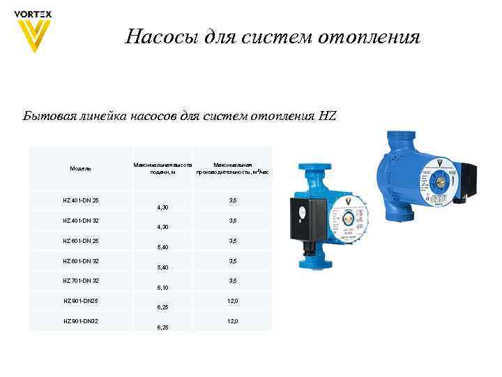
Consider a circulation pump with a flow rate of up to 3 m 3 / hour (25/6) 25 mm thread diameter, 6 m - head.
When choosing a pump, it is advisable to look at the actual graph of the pressure-flow characteristic. If it is not available, then I recommend simply drawing a straight line on the chart with the specified parameters
Here the distance between points A and B is minimal, and therefore this pump is suitable.
Its parameters will be:
Maximum consumption 2 m 3 / hour
Max head 2 meters