- Calculation for parallel and series connection
- Current calculation
- EXAMPLES OF TASKS
- Part 1
- Part 2
- Total power and its components
- Resistive load
- capacitive load
- Inductive load
- Electrical circuits and their varieties
- Characteristics
- For AC
- 1. Calculator of power dissipation and flowing current depending on resistance and applied voltage.
- Calculation of electrical circuits
- How to save money
- Resistance change:
- Using formulas
- For AC
- Questions about work and electric power
- Interesting info on the topic
- AC Power Norms
- Electrical circuit conversion method
- Calculation of a circuit with one power supply
- Calculation of an extensive electrical circuit with multiple power supplies
- Calculation of current for a single-phase network
- Conclusion
- Lesson summary
Calculation for parallel and series connection
When calculating the circuit of an electronic device, it is often necessary to find the power that is released on a single element. Then you need to determine what voltage drops on it, if we are talking about a serial connection, or what current flows when connected in parallel, we will consider specific cases.
Here Itotal is equal to:
I=U/(R1+R2)=12/(10+10)=12/20=0.6
General power:
P=UI=12*0.6=7.2 Watts
On each resistor R1 and R2, since their resistance is the same, the voltage drops along:
U=IR=0.6*10=6 Volt
And stands out by:
Pon a resistor\u003d UI \u003d 6 * 0.6 \u003d 3.6 Watts
Then, with a parallel connection in such a scheme:
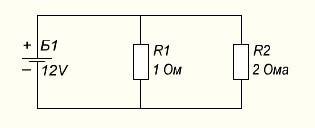
First, we look for I in each branch:
I1=U/R1=12/1=12 Amps
I2=U/R2=12/2=6 Amps
And stands out on each by:
PR1\u003d 12 * 6 \u003d 72 Watts
PR2\u003d 12 * 12 \u003d 144 watts
All stand out:
P=UI=12*(6+12)=216 Watts
Or through the total resistance, then:
Rgeneral=(R1*R2)/( R1+R2)=(1*2)/(1+2)=2/3=0.66 ohm
I=12/0.66=18 Amps
P=12*18=216 Watts
All calculations matched, so the found values are correct.
Current calculation
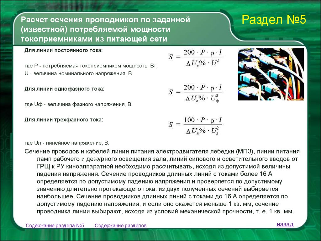
The magnitude of the current is calculated by power and is necessary at the stage of designing (planning) a dwelling - an apartment, a house.
- The choice of the supply cable (wire) through which power consumption devices can be connected to the network depends on the value of this value.
- Knowing the voltage of the electrical network and the full load of electrical appliances, it is possible, using the formula, to calculate the strength of the current that needs to be passed through the conductor (wire, cable). According to its size, the cross-sectional area of \u200b\u200bthe veins is selected.
If the electrical consumers in the apartment or house are known, it is necessary to perform simple calculations in order to properly mount the power supply circuit.
Similar calculations are performed for production purposes: determining the required cross-sectional area of cable cores when connecting industrial equipment (various industrial electric motors and mechanisms).
EXAMPLES OF TASKS
Part 1
1. The strength of the current in the conductor was increased by 2 times. How will the amount of heat released in it per unit time change, with the resistance of the conductor unchanged?
1) will increase by 4 times
2) will decrease by 2 times
3) will increase by 2 times
4) decrease by 4 times
2.The length of the electric stove spiral was reduced by 2 times. How will the amount of heat released in the spiral per unit of time change at a constant mains voltage?
1) will increase by 4 times
2) will decrease by 2 times
3) will increase by 2 times
4) decrease by 4 times
3. The resistance of the resistor \(R_1 \) is four times less than the resistance of the resistor \(R_2 \). Current work in resistor 2
1) 4 times more than in resistor 1
2) 16 times more than resistor 1
3) 4 times less than in resistor 1
4) 16 times less than in resistor 1
4. The resistance of the resistor \(R_1 \) is 3 times the resistance of the resistor \(R_2 \). The amount of heat that will be released in the resistor 1
1) 3 times more than in resistor 2
2) 9 times more than resistor 2
3) 3 times less than in resistor 2
4) 9 times less than in resistor 2
5. The circuit is assembled from a power source, a light bulb and a thin iron wire connected in series. The light bulb will glow brighter if
1) replace the wire with a thinner iron
2) reduce the length of the wire
3) swap wire and light bulb
4) replace the iron wire with nichrome
6. The figure shows a bar chart. It shows the voltage values at the ends of two conductors (1) and (2) of the same resistance. Compare the values of current work \( A_1 \) and \( A_2 \) in these conductors for the same time.
1) \(A_1=A_2 \)
2) \( A_1=3A_2 \)
3) \( 9A_1=A_2 \)
4) \( 3A_1=A_2 \)
7. The figure shows a bar chart. It shows the values of the current strength in two conductors (1) and (2) of the same resistance. Compare the current work values \( A_1 \) and \ ( A_2 \) in these conductors for the same time.
1) \(A_1=A_2 \)
2) \( A_1=3A_2 \)
3) \( 9A_1=A_2 \)
4) \( 3A_1=A_2 \)
8. If you use lamps with a power of 60 and 100 W in a chandelier to illuminate the room, then
A. A large current will be in a 100W lamp.
B. A 60 W lamp has more resistance.
True(s) is(are) the statement(s)
1) only A
2) only B
3) both A and B
4) neither A nor B
9. An electric stove connected to a direct current source consumes 108 kJ of energy in 120 seconds. What is the current strength in the tile spiral if its resistance is 25 ohms?


1) 36 A
2) 6 A
3) 2.16 A
4) 1.5 A
10. An electric stove with a current of 5 A consumes 1000 kJ of energy. What is the time for the current to pass through the spiral of the tile if its resistance is 20 ohms?
1) 10000 s
2) 2000s
3) 10 s
4) 2 s
11. The nickel-plated coil of the electric stove was replaced with a nichrome coil of the same length and cross-sectional area. Establish a correspondence between physical quantities and their possible changes when the tile is connected to the electrical network. Write in the table the selected numbers under the corresponding letters. Numbers in the answer may be repeated.
PHYSICAL QUANTITY
A) electrical resistance of the coil
B) the strength of the electric current in the spiral
B) electric current power consumed by the tile
NATURE OF THE CHANGE
1) increased
2) decreased
3) has not changed
12. Establish a correspondence between physical quantities and the formulas by which these quantities are determined. Write in the table the selected numbers under the corresponding letters.
PHYSICAL QUANTITIES
A) work current
B) current strength
b) current power
FORMULA
1) \( \frac{q}{t} \)
2) \(qU \)
3) \( \frac{RS}{L} \)
4) \(UI \)
5) \( \frac{U}{I} \)
Part 2
13.The heater is connected in series with a rheostat with a resistance of 7.5 ohms to a network with a voltage of 220 V. What is the resistance of the heater if the power of the electric current in the rheostat is 480 W?
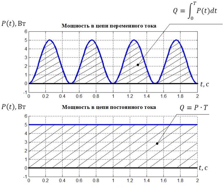
Total power and its components
Electric power is a quantity responsible for the rate of change or transmission of electricity. Apparent power is denoted by the letter S and is found as the product of the effective values of current and voltage. Its unit of measurement is volt-ampere (VA; V A).
Apparent power can be made up of two components: active (P) and reactive (Q).
Active power is measured in watts (W; W), reactive power is measured in vars (Var).
It depends on what type of load is included in the power consumption chain.
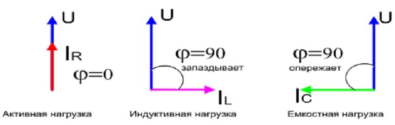
Resistive load
This type of load is an element that resists electric current. As a result, the current does the work of heating the load, and electricity is converted into heat. If a resistor of any resistance is connected in series with the battery, then the current passing through the closed circuit will heat it until the battery is discharged.
Attention! An example of a thermal electric heater (TENA) can be cited as an active load in AC networks. Heat dissipation on it is the result of the work of electricity
Such consumers also include coils of light bulbs, electric stoves, ovens, an iron, and a boiler.
capacitive load
Such loads are devices that can accumulate energy in electric fields and create a movement (oscillation) of power from the source to the load and vice versa.Capacitive loads are capacitors, cable lines (capacitance between the cores), capacitors and inductors connected in series and in parallel in the circuit. Audio power amplifiers, synchronous electric motors in overexcited mode also load the lines of the capacitive component.
Inductive load
When the consumer of electricity is a certain equipment, which includes:
- transformers;
- three-phase asynchronous motors, pumps.
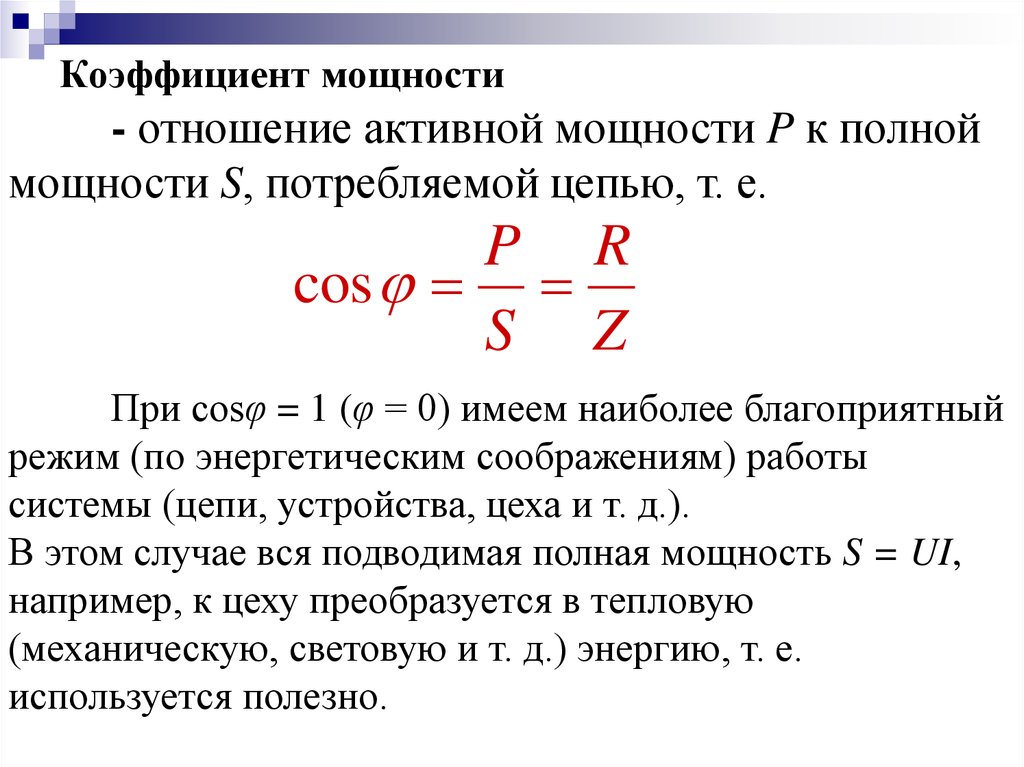
On the plates attached to the equipment, you can see such a characteristic as cos ϕ. This is the phase shift factor between current and voltage in the AC mains into which the equipment will be connected. It is also called the power factor, the closer cos ϕ to unity, the better.
Important! When a device contains inductive or capacitive components: transformers, chokes, windings, capacitors, the sinusoidal current lags the voltage by some angle in phase. Ideally, the capacitance provides a -900 phase shift, and the inductance - + 900
 Cos ϕ values depending on the type of load
Capacitive and inductive components together form reactive power. Then the formula for total power is:
S = √ (P2 + Q2),
where:
- S is the apparent power (VA);
- P is the active part (W);
- Q is the reactive part (Var).
If you show this graphically, then you can see that the vector addition of P and Q will be the full value of S - the hypotenuse of the triangle of power.
Graphical explanation of the essence of full power
Electrical circuits and their varieties
An electrical circuit is a complex of devices and individual objects that are connected in a given way. They provide a path for the passage of electricity.To characterize the ratio of the charge flowing within each individual conductor for some time to the duration of this time, a certain physical quantity is used. And this is the current in the electrical circuit.
The composition of such a chain includes an energy source, energy consumers, i.e. load and wires. They are divided into two varieties:
- Unbranched - the current moving from the generator to the energy consumer does not change in value. For example, this is lighting, which includes only one light bulb.
- Branched - chains that have some branches. The current, moving from the source, is divided and goes to the load along several branches. However, its meaning changes.
An example is lighting that includes a multi-arm chandelier.
A branch is one or more components connected in series. The movement of current goes from a node with a high voltage to a node with a minimum value. In this case, the incoming current at the node coincides with the outgoing current.
Circuits can be non-linear and linear. If in the first there are one or more elements where there is a dependence of values on current and voltage, then in the second the characteristics of the elements do not have such a dependence. In addition, in circuits characterized by direct current, its direction does not change, but under the condition of alternating current, it changes taking into account the time parameter.
Characteristics
Alternating current flows through a circuit and changes its direction with magnitude. Creates a magnetic field. Therefore, it is often called a periodic sinusoidal alternating electric current. According to the law of a curved line, its value changes after a specific period of time. That is why it is called sinusoidal. Has its own settings.Of the important ones, it is worth specifying the period with frequency, amplitude and instantaneous value.
The period is the time during which a change in electric current occurs, and then it repeats again. Frequency is a period per second. It is measured in hertz, kilohertz and millihertz.
Amplitude - current maximum value with voltage and flow efficiency over a full cycle. Instantaneous value - an alternating current or voltage that occurs in a specific time.
 AC Specifications
For AC
However, for an AC electrical circuit, the total, active and reactive, as well as the power factor (cosF), must be taken into account. We discussed all these concepts in more detail in this article.
We only note that in order to find the total power in a single-phase network for current and voltage, you need to multiply them:
S=UI
The result will be obtained in volt-amperes, in order to determine the active power (watts), you need to multiply S by the cosФ coefficient. It can be found in the technical documentation for the device.
P=UIcos
To determine reactive power (reactive volt-amperes), sinФ is used instead of cosФ.
Q=UIsin
Or express from this expression:
And from here calculate the desired value.
It is also easy to find the power in a three-phase network; to determine S (total), use the calculation formula for current and phase voltage:
S=3Uf/f
And knowing Ulinear:
S=1.73*UlIl
1.73 or the root of 3 - this value is used for calculations of three-phase circuits.
Then by analogy to find P active:
P=3Uf/f*cosФ=1.73*UlIl*cosФ
Reactive power can be determined:
Q=3Uf/f*sinФ=1.73*UlIl*sinФ
This ends the theoretical information and we move on to practice.
one.Calculator of power dissipation and flowing current depending on resistance and applied voltage.
Ohm's law real time demo.
For reference
In this example, you can increase the voltage and resistance of the circuit. These changes in real time will change the current flowing in the circuit and the power dissipated in the resistance.
If we consider audio systems, you must remember that the amplifier produces a certain voltage for a certain load (resistance). The ratio of these two quantities determines the power.
The amplifier can output a limited amount of voltage depending on the internal power supply and current source. The power that the amplifier can supply to a certain load (for example, 4 ohms) is also exactly limited.
In order to get more power, you can connect a load with a lower resistance (for example, 2 ohms) to the amplifier. Please note that when using a load with less resistance - say twice (it was 4 ohms, it became 2 ohms) - the power will also double (provided that this power can be provided by the internal power supply and current source).
If we take for example a mono amplifier with a power of 100 watts into a 4 ohm load, knowing that it can deliver a voltage of no more than 20 volts to the load.
If you put sliders on our calculator
Voltage 20 Volts
Resistance 4 Ohm
You'll get
Power 100 watts
If you move the resistance slider by 2 ohms, you will see the power doubled to 200 watts.
In a general example, the current source is a battery (not a sound amplifier), but the dependences of current, voltage, resistance, and resistance are the same in all circuits.


Calculation of electrical circuits
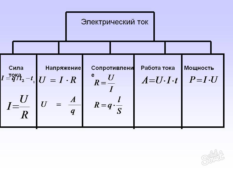
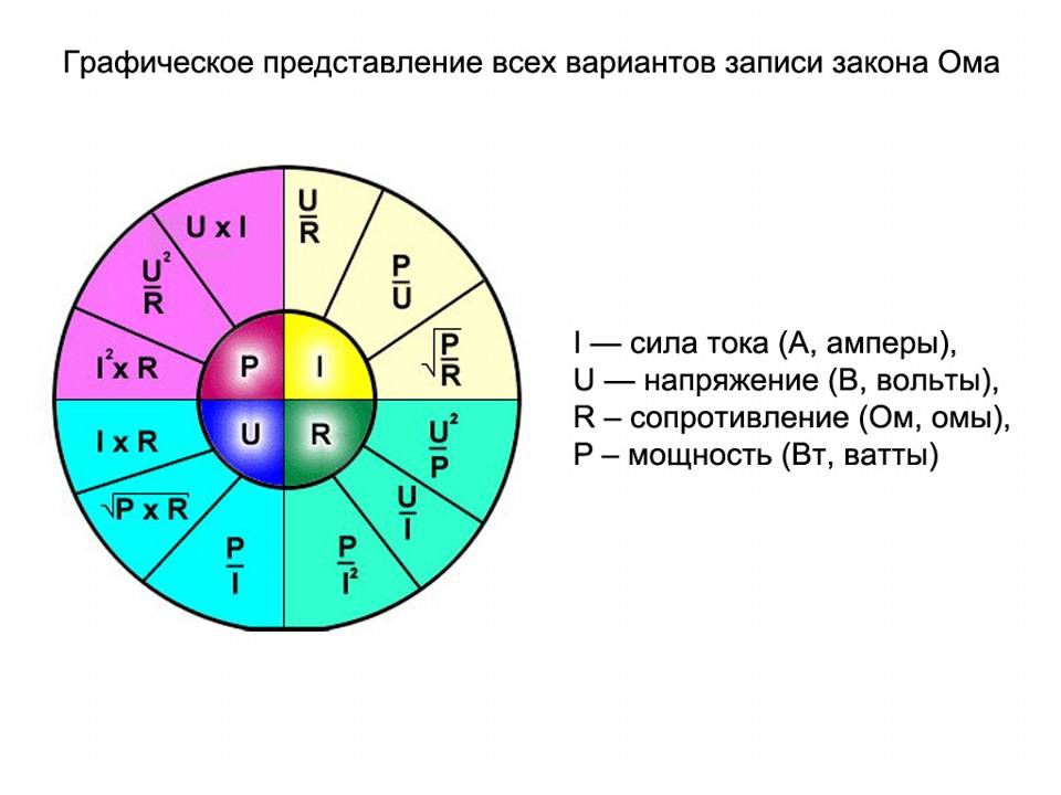
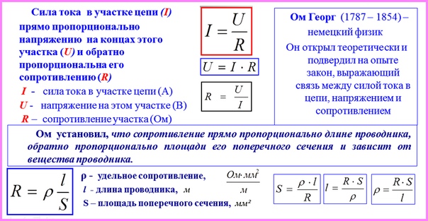
All formulas used to calculate electrical circuits follow from one another.
 Relationships of electrical characteristics
So, for example, according to the power calculation formula, you can calculate the current strength if P and U are known.
To find out what current an iron (1100 W) connected to a 220 V network will consume, you need to express the current strength from the power formula:
I = P/U = 1100/220 = 5 A.
Knowing the calculated resistance of the spiral of the electric stove, you can find P device. Power through resistance is found by the formula:
P = U2/R.
There are several methods that allow solving the tasks set by calculating various parameters of a given circuit.
 Methods for calculating electrical circuits
Calculation of power for circuits of various kinds of current helps to correctly assess the condition of power lines. Household and industrial devices, selected in accordance with the given parameters Pnom and S, will work reliably and withstand maximum loads for years.
How to save money
Installing a two-tariff meter saves electricity heating costs. Moscow tariffs for apartments and houses equipped with stationary electric heating installations distinguish between two costs:
- 4.65 r from 7:00 to 23:00.
- 1.26 r from 23:00 to 7:00.
Then you will spend, subject to round-the-clock operation, 9 kW of an electric boiler turned on for a third of the power:
9*0.3*12*4.65 + 9*0.3*12*1.26 = 150 + 40 = 190 rubles
The difference in daily consumption is 80 rubles. In a month you will save 2400 rubles. What justifies the installation of a two-tariff meter.

The second way to save money when using a two-tariff meter is to use automatic control devices for electrical appliances. It consists in assigning the peak consumption of an electric boiler, boiler and other things at night, then most of the electricity will be charged at 1.26, and not at 4.65. While you are at work, the boiler can either turn off completely or operate in low energy mode, for example, at 10% of power. To automate the operation of the electric boiler, you can use programmable digital thermostats or boilers with the ability to program.
In conclusion, I would like to note that heating a house with electricity is a rather expensive method, regardless of the specific method, whether it is an electric boiler, a convector or another electric heater. They come to him only in cases where there is no way to connect to the gas. In addition to the costs of operating an electric boiler, you are waiting for the initial costs of registering a three-phase input of electricity.
The main chores are:
- registration of a package of documents, including technical specifications, electrical project, etc.;
- organization of grounding;
- the cost of a cable for connecting a house and wiring a new wiring;
- counter installation.
Moreover, you may be denied a three-phase input and an increase in power if there is no such technical possibility in your area, when the transformer substations are already operating at their limit. The choice of the type of boiler and heating depends not only on your desires, but also on the capabilities of the infrastructure.
This concludes our short article. We hope that now it has become clear to you what the real consumption of electricity is by an electric boiler and how you can reduce the cost of heating a house with electricity.
Number of blocks: 18 | Total characters: 24761
Number of donors used: 7
Information for each donor:
Resistance change:
In the following diagram, you can see the difference in resistance between the systems depicted on the right and left side of the figure. The resistance to water pressure in the tap is counteracted by the valve, depending on the degree of opening of the valve, the resistance changes.
The resistance in a conductor is shown as a narrowing of the conductor, the narrower the conductor, the more it opposes the passage of current.
You may notice that the voltage and water pressure are the same on the right and left side of the circuit.
You need to pay attention to the most important fact. Depending on the resistance, the current increases and decreases.
Depending on the resistance, the current increases and decreases.
On the left, with the valve fully open, we see the largest flow of water. And at the lowest resistance, we see the largest flow of electrons (amperage) in the conductor.
On the right, the valve is closed much more and the flow of water has also become much larger.
The narrowing of the conductor also halved, which means that the resistance to the flow of current has doubled. As we can see, two times less electrons flow through the conductor due to the high resistance.
For reference
Please note that the narrowing of the conductor shown in the diagram is only used as an example of resistance to the flow of current. In real conditions, the narrowing of the conductor does not greatly affect the flowing current
Semiconductors and dielectrics can provide much greater resistance.
The tapering conductor in the diagram is shown only as an example, to understand the essence of the ongoing process. The formula of Ohm's law is the dependence of resistance and current strength
I=E/R
As you can see from the formula, the current strength is inversely proportional to the resistance of the circuit.
More resistance = less current
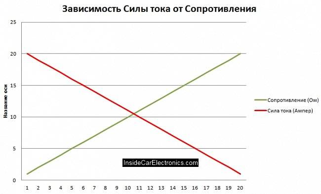
* provided that the voltage is constant.
Using formulas
This angle characterizes the phase shift in variable U circuits containing inductive and capacitive elements. To calculate the active and reactive components, trigonometric functions are used, which are used in formulas. Before calculating the result using these formulas, it is necessary, using calculators or Bradis tables, to determine sin φ and cos φ. After that, according to the formulas

I will calculate the desired parameter of the electrical circuit. But it should be taken into account that each of the parameters calculated according to these formulas, due to U, which is constantly changing according to the laws of harmonic oscillations, can take either an instantaneous, or root-mean-square, or intermediate value. The three formulas shown above are valid for rms values of current and U. Each of the other two values is the result of a calculation procedure using a different formula that takes into account the passage of time t:
But this is not all the nuances. For example, for power lines, formulas are used that include wave processes. And they look different. But that's a completely different story...
For AC
However, for an AC electrical circuit, the total, active and reactive, as well as the power factor (cosF), must be taken into account. We discussed all these concepts in more detail in this article.
We only note that in order to find the total power in a single-phase network for current and voltage, you need to multiply them:
S=UI
The result will be obtained in volt-amperes, in order to determine the active power (watts), you need to multiply S by the cosФ coefficient.It can be found in the technical documentation for the device.
P=UIcos
To determine reactive power (reactive volt-amperes), sinФ is used instead of cosФ.
Q=UIsin
Or express from this expression:
And from here calculate the desired value.
It is also easy to find the power in a three-phase network; to determine S (total), use the calculation formula for current and phase voltage:
And knowing Ulinear:
1.73 or the root of 3 - this value is used for calculations of three-phase circuits.
Then by analogy to find P active:
Reactive power can be determined:
This ends the theoretical information and we move on to practice.
Questions about work and electric power
Theoretical questions for the work and power of electric current can be as follows:
- What is the physical quantity of electric current work? (The answer is given in our article above).
- What is electrical power? (Answer given above).
- Define the Joule-Lenz law. Answer: The work of an electric current that flows through a fixed conductor with resistance R is converted into heat in the conductor.
- How is the work of current measured? (Answer above).
- How is power measured? (Answer above).
This is a sample list of questions. The essence of theoretical questions in physics is always the same: to check the understanding of physical processes, the dependence of one quantity on another, knowledge of the formulas and units of measurement adopted in the international SI system.


Interesting info on the topic
A three-phase power supply scheme is used in production. The total voltage of such a network is 380 V. Also, such wiring is installed on multi-storey buildings, and then distributed among apartments. But there is one nuance that affects the final voltage in the network - connecting the core under voltage results in 220 V.Three-phase, unlike single-phase, does not give distortions when connecting power equipment, since the load is distributed in the shield. But to bring a three-phase network to a private house, a special permit is required, therefore a scheme with two cores is widespread, one of which is zero.
AC Power Norms
Voltage and power are what every person living in an apartment or a private house needs to know. The standard AC voltage in an apartment and a private house is expressed in the amount of 220 and 380 watts. As for determining the quantitative measure of the strength of electrical energy, it is necessary to add the electric current to the voltage or measure the required indicator with a wattmeter. At the same time, to make measurements with the last device, you need to use probes and special programs.
 What is AC Power
AC power is determined by the ratio of the amount of current with time, which produces work in a certain time. An ordinary user uses the power indicator transmitted to him by the supplier of electrical energy. As a rule, it is equal to 5-12 kilowatts. These figures are enough to ensure the operability of the necessary household electrical equipment.
This indicator depends on what external conditions for the supply of energy to the house, what limiting current devices (automatic or semiautomatic devices) are installed that regulate the moment when power tanks arrive at the consumer source. This is done at different levels, from the household electrical panel to the central electrical distribution unit.
Power norms in the AC network
Electrical circuit conversion method
How to determine the current strength in individual circuits of complex circuits? To solve practical problems, it is not always necessary to clarify the electrical parameters for each element. To simplify the calculations, special conversion techniques are used.
Calculation of a circuit with one power supply
For a serial connection, the summation of electrical resistances considered in the example is used:
Req = R1 + R2 + … + Rn.
The loop current is the same at any point in the circuit. You can check it in the break of the control section with a multimeter. However, on each individual element (with different ratings), the device will show a different voltage. By Kirchhoff's second law you can refine the calculation result:
E = Ur1 + Ur2 + Urn.
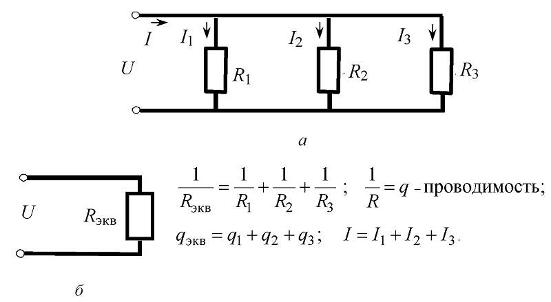 Parallel connection of resistors, circuitry and formulas for calculations
In this variant, in full accordance with Kirchhoff's first postulate, the currents are separated and combined at the input and output nodes. The direction shown in the diagram is chosen taking into account the polarity of the connected battery. According to the principles discussed above, the basic definition of voltage equality on individual components of the circuit is preserved.
The following example demonstrates how to find the current in individual branches. The following initial values were taken for calculation:
- R1 = 10 Ohm;
- R2 = 20 ohm;
- R3= 15 ohm;
- U = 12 V.
The following algorithm will determine the characteristics of the circuit:
basic formula for three elements:
Rtot = R1*R2*R3/(R1*R2 + R2*R3 + R1*R3.
- substituting the data, calculate Rtot = 10 * 20 * 15 / (10 * 20 + 20 * 15 + 10 * 15) = 3000 / (200 + 300 + 150) = 4.615 ohms;
- I \u003d 12 / 4.615 ≈ 2.6 A;
- I1 \u003d 12 / 10 \u003d 1.2 A;
- I2 = 12/20 = 0.6 A;
- I3 = 12/15 = 0.8 A.
As in the previous example, it is recommended to check the calculation result.When connecting components in parallel, the equality of the input currents and the total value must be observed:
I \u003d 1.2 + 0.6 + 0.8 \u003d 2.6 A.
If a sinusoidal source signal is used, the calculations become more complicated. When a transformer is connected to a single-phase 220V socket, losses (leakage) in idle mode will have to be taken into account. In this case, the inductive characteristics of the windings and the coupling (transformation) coefficient are essential. Electrical resistance (XL) depends on the following parameters:
- signal frequency (f);
- inductance (L).
Calculate XL by the formula:
XL \u003d 2π * f * L.
To find the resistance of a capacitive load, the expression is suitable:
Xc \u003d 1 / 2π * f * C.
It should not be forgotten that in circuits with reactive components, the phases of current and voltage are shifted.
Calculation of an extensive electrical circuit with multiple power supplies
Using the considered principles, the characteristics of complex circuits are calculated. The following shows how to find the current in a circuit when there are two sources:
- designate components and basic parameters in all circuits;
- make equations for individual nodes: a) I1-I2-I3=0, b) I2-I4+I5=0, c) I4-I5+I6=0;
- in accordance with Kirchhoff's second postulate, the following expressions for contours can be written: I) E1=R1 (R01+R1)+I3*R3, II) 0=I2*R2+I4*R4+I6*R7+I3*R3, III ) -E2=-I5*(R02+R5+R6)-I4*R4;
- check: d) I3+I6-I1=0, outer loop E1-E2=I1*(r01+R1)+I2*R2-I5*(R02+R5+R6)+I6*R7.
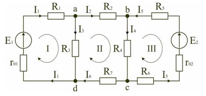 Explanatory diagram for calculation with two sources
Calculation of current for a single-phase network
Current is measured in amperes. To calculate power and voltage, the formula I = P/U is used, where P is the power or total electrical load, measured in watts.This parameter must be entered in the technical passport of the device. U - represents the voltage of the calculated network, measured in volts.
The relationship between current and voltage is clearly visible in the table:
| Electrical appliances and equipment | Power consumption (kW) | Current (A) |
| Washing machines | 2,0 – 2,5 | 9,0 – 11,4 |
| Stationary electric stoves | 4,5 – 8,5 | 20,5 – 38,6 |
| microwaves | 0,9 – 1,3 | 4,1 – 5,9 |
| Dishwashers | 2,0 – 2,5 | 9,0 – 11,4 |
| Refrigerators, freezers | 0,14 – 0,3 | 0,6 – 1,4 |
| Electric floor heating | 0,8 – 1,4 | 3,6 – 6,4 |
| Electric meat grinder | 1,1 – 1,2 | 5,0 – 5,5 |
| Electric kettle | 1,8 – 2,0 | 8,4 – 9,0 |
Thus, the relationship between power and current makes it possible to perform preliminary calculations of loads in a single-phase network. The calculation table will help you choose the required wire section, depending on the parameters.


| Conductor core diameters (mm) | Conductor cross section (mm2) | Copper conductors | Aluminum conductors | ||
| Current (A) | Power, kWt) | Strength (A) | Power, kWt) | ||
| 0,8 | 0,5 | 6 | 1,3 | ||
| 0,98 | 0,75 | 10 | 2,2 | ||
| 1,13 | 1,0 | 14 | 3,1 | ||
| 1,38 | 1,5 | 15 | 3,3 | 10 | 2,2 |
| 1,6 | 2,0 | 19 | 4,2 | 14 | 3,1 |
| 1,78 | 2,5 | 21 | 4.6 | 16 | 3,5 |
| 2,26 | 4,0 | 27 | 5,9 | 21 | 4,6 |
| 2,76 | 6,0 | 34 | 7,5 | 26 | 5,7 |
| 3,57 | 10,0 | 50 | 11,0 | 38 | 8,4 |
| 4,51 | 16,0 | 80 | 17,6 | 55 | 12,1 |
| 5,64 | 25,0 | 100 | 22,0 | 65 | 14,3 |
Conclusion
As you can see, finding the power of a circuit or its section is not difficult at all, no matter if we are talking about a constant or a change. It is more important to correctly determine the total resistance, current and voltage
By the way, this knowledge is already enough to correctly determine the parameters of the circuit and select the elements - how many watts to select resistors, cross-sections of cables and transformers. Also, be careful when calculating S total when calculating the radical expression. It is only worth adding that when paying utility bills, we pay for kilowatt-hours or kWh, they are equal to the amount of power consumed over a period of time. For example, if you connected a 2 kilowatt heater for half an hour, then the meter will wind up 1 kW / h, and for an hour - 2 kW / h, and so on by analogy.


Finally, we recommend watching a useful video on the topic of the article:
Also read:
- How to determine the power consumption of appliances
- How to calculate cable sections
- Marking resistors for power and resistance
Lesson summary
In this lesson, we considered various tasks for the mixed resistance of conductors, as well as for the calculation of electrical circuits.


