- Possible problems
- Doesn't turn on
- Exaggerates voltage values
- The display is too "faint" or "bright"
- Incorrect display of numbers
- The "beeper" does not work in dialing mode
- Backlight not working
- Inhibited operation of the device
- Screen turns on and off
- What parameters can be measured with a multimeter
- What is the voltage at the outlet?
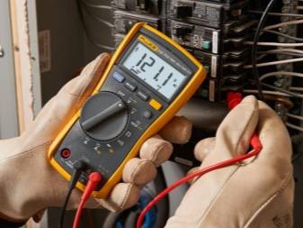
- How to check the voltage in the outlet with a universal multimeter
- Symbols on the device
- Safety precautions before work
- How to test a capacitor with a multimeter
- And if not in the outlet.
- How to check the voltage in the outlet with a multimeter
- External structure and functions
- The structure of the electronic multimeter
- Switch position
- Peculiarities
- How to measure 220 with a multimeter
- How to check the voltage in the outlet with a multimeter - step by step instructions
- Basic principles of current measurement
- Socket current measurement
- Conclusion
Possible problems
No instrument, including a digital multimeter, is without the ability to display incorrect or incomplete data, or not display them at all.
Doesn't turn on
If the tester does not show anything, check if it is turned on at all. Next, check if there is a battery in it, if it is so discharged that it stops turning on. Check if the display is intact. If the tester is turned on, but with a new battery it does not show anything, the reasons are as follows:
- the power wire or terminal has fallen off, the battery is damaged or its contents have leaked out;
- the device fell, hit, got wet, which caused the display to lose contact with the interface module (digital matrix controller);
- when aggressive chemicals hit, liquid crystals leaked out and the reflective film was damaged - the screen becomes not just inoperative, but whitish;
- the central microcircuit that controls the operation of the device is faulty.
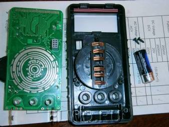
If you have the necessary knowledge and repair skills, you can disassemble the device. Finding out what is wrong with it is quite within your power. In the latter case, when the ADC (microchip with converter) does not work, the multimeter cannot be repaired. The only exception is the situation when there is another multimeter at hand, in which the screen, buttons and / or switch are damaged.
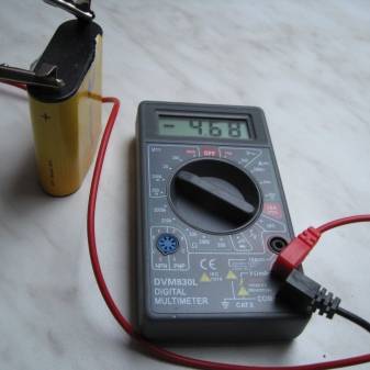
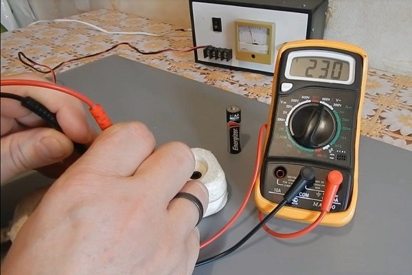
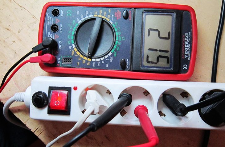
Exaggerates voltage values
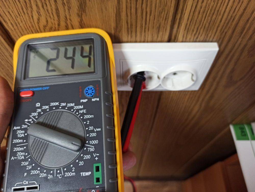
If the battery is low, the device will start to "lie". There were cases when the "outlet" voltage instead of 220-240 V showed, for example, 260-310. This happens when the battery is discharged to 7-8 volts. Replace the battery with a new one and repeat the measurements in the same place. Most likely this issue will be resolved.
The display is too "faint" or "bright"
Easy highlighting of all sectors of numbers against the background of the necessary ones (for example, the number 8 against the background of the number 3) is an indicator that you came across a battery with a voltage that accidentally turned out to be higher than 9 V, for example, 10.2). This is also observed when the tester is forcibly powered from the outlet with a 12-volt power adapter, which is an excess. Do not supply voltage greater than 9V.
A pale glow of the display sectors (digits are barely visible) indicates that the battery is discharged to 6 V, the multimeter is about to turn off. Change battery.
Incorrect display of numbers
For example, if you saw instead of the number "8" capital "L", "stroke", "space", "minus", capital or lowercase "P" (or "U", "C", "A", "E" ), “soft sign” (all this should not be), then the display controller has failed. In some cases, the corresponding elements of the digital matrix may be partially damaged.
If you have a working matrix from exactly the same tester, in which the “motherboard” burned out or crashed, you can rearrange the surviving display from it, and then compare the results. When the same problems are found, suspicion already falls on the display controller. Here you can't do anything. Buy a new multimeter.
The "beeper" does not work in dialing mode
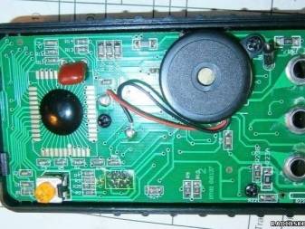
Some multimeters have a button that turns off the squeak of the device when the line rings. Make sure the alarm is not turned off. Otherwise, the “tweeter” wire was disconnected from the board, or it was defective or damaged during the last careless repair of the device. Install a sounder from another similar tester. You can work without it.
Backlight not working
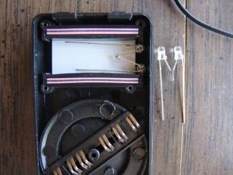
If you did not turn off the backlight using a special button, or the battery did not “sat down”, then a sign of a non-working backlight may be defective or fallen off LEDs. Check (and replace) them. You can work without backlight.
Inhibited operation of the device
Slow multimeter response to changing conditions, such as connecting other resistors, indicates defective accessories on its board. So, if the resistance does not change immediately when a resistor is added, in the standby mode the last digit “0” changes to “1” and vice versa, then the reason is a malfunction of the capacitors on the device board.
Screen turns on and off
When the screen lights up at startup, but goes out a few seconds after turning on, the problem is in the multimeter master oscillator. Since the ZG is part of the main microcircuit, you are unlikely to achieve anything here, this element cannot be replaced. The entire device must be replaced.
What parameters can be measured with a multimeter
This hand-held meter is designed for various electrical tests.
The multimeter is a multifunctional device that can determine the following technical parameters:
- voltage - constant and variable;
- resistance range;
- capacity;
- frequency;
- inductance;
- strength of direct and alternating current;
- temperature regime;
- transistor gain;
- checking diodes and transistors;
- calculation of electrical resistance with the transmission of a signal of reduced circuit resistance.
In many models, there is a knob on the front panel that facilitates switching values.
Some multimeters have additional equipment and can measure mass, meter or time in seconds.
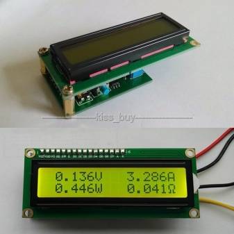
Measurement results are visible on the built-in monitor. On the side of the device there are two sockets for probes - red (positive value) and black (with negative potential).
What is the voltage at the outlet?
More precisely, what should it be? On the territory of Russia, the most common indicators in the centralized network are 220 and 380 volts, with a frequency of 50 Hz. An acceptable deviation, in one direction or another, is considered to be a value of 10%. That is, an error up to 198 or 242 volts will be normal.


These fluctuations can depend both on a large load on the network, on high-power electrical appliances (heaters, boilers, welding machines), and on a serving power plant.But whatever the reason, it is recommended to sometimes control the voltage at the outlet at home in order to avoid possible unpleasant consequences.
How to check the voltage in the outlet with a universal multimeter
Electricity in the home is a common occurrence. Everyone uses it. Everyone knows that there is a voltage of 220 V in the network and all household appliances are designed for this voltage. But rarely does anyone look into the instructions, where the manufacturer indicates the permissible voltage deviation from the nominal voltage at which a particular device can operate without harming its electrical circuit. But it’s still worth watching, all the more so to be sure whether 220 V is really stably present in the network.
In fact, the voltage is constantly changing, unless, of course, special stabilizers are provided in the house that even out all the jumps, carefully protecting the equipment. In an ordinary outlet, you can observe both 180 and 270 V. Not every technique can withstand such a tough attitude towards itself.
What to do to protect yourself from the risk of losing electronics? Firstly, it is necessary to put an overvoltage cut-off block, which are commercially available, at the input of the electrical distribution panel. Secondly, purchase an electronic multimeter. How to check the voltage in the outlet with a multimeter? More on this below.
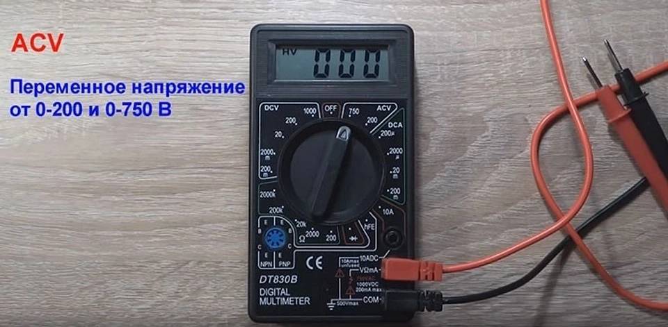
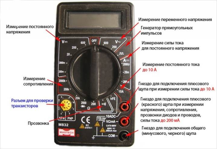
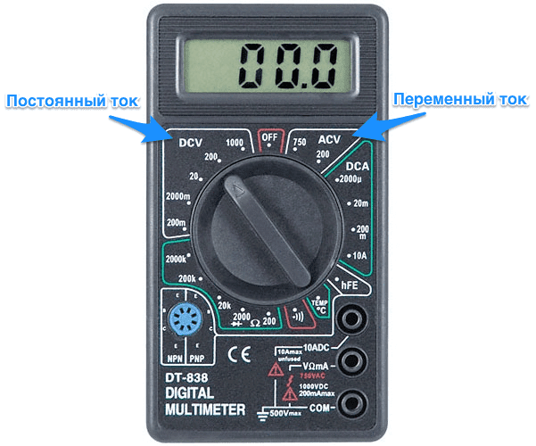
Symbols on the device
You can check the voltage with a multimeter by switching the latter to the DC or AC voltage measurement mode. Next to the highest measurement range for direct and alternating voltage, there is an icon in the form of a lightning bolt with an arrow at the end - an identification symbol indicating life-threatening voltage.
The higher the frequency, the lower the limit: experienced craftsmen noted cases when even an audio frequency voltage of up to 40 V supplied from an amplifier to any of the hundreds of watt speakers was electric. So, for example, there have been cases of electric shocks with a voltage of 20 V with a frequency of 8 kHz. Be careful when working under voltage of several tens or hundreds of volts: accidentally touching a live part can be fatal for an unprotected beginner.
The following icons also make sense:
- the icons "V~" and "A~" mean variable voltage and amperage, respectively;
- hFE - current amplification factor of transistors (specified in reference books as h21);
- speaker or tweeter icon - dialing mode (resistance up to 200 ohms, at 50 ohms the sounder is triggered);
- diode icon - checking diodes and transistors without the need to remove them from the board;
- k - the prefix "kilo" (kilooms);
- M - "mega" (megaohms);
- m - "milli" (most often these are milliamps);
- lowercase Greek letter "mu" - the prefix "micro" (microamps);
- capital Greek "omega" - resistance in ohms;
- F - farads (capacitor capacitance);
- Hz – hertz (current frequency);
- degree icon or marker "temp." – measurements of air temperature;
- DC - from English. "direct current", direct current parameters;
- AC - from English. "alternating current", alternating current parameters.
The last two markers sometimes replace the dash (direct current) and "tilde" (alternating) icon, respectively. It is recommended to remember them - at least those responsible for measuring current, voltage and resistance. Others require specialized knowledge.
Safety precautions before work
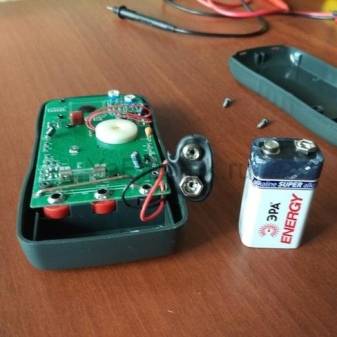
The multitester is a multifunctional portable device that is powered by a battery (usually a crown) and is a convenient and, most importantly, safe tool for the end user. But there are certain rules for its use.
"Krona" - a battery of galvanic batteries, overall dimensions 48.5X26.5X17.5 mm. The weight of the battery is about 53-55 grams. Output voltage - 9 V, average capacity - 600 mAh
The tester itself is equipped with internal overload and overvoltage protection. But without following the rules below, it can also easily “burn out”, partially fail. To avoid this, there are a number of general rules for the safe operation of a digital tester.
When measuring input AC voltage:
- If the preliminary value of the measured voltage is not defined, the switch is set to the largest range.
- Do not apply more than 750 V to the input to avoid damage to the internal circuit.
Hands without dielectric gloves should not touch the components of the electrical network.
When measuring DC and AC input current:
- If the preliminary value of the measured current is not defined, the switch is set to the largest range.
- If the LCD is set to “1”, place the trigger on the next range in the direction of increasing the maximum value.
- When working with the “20A” connector, the testing time should not exceed 15 seconds, since there is no fuse for this mode.
When measuring the internal resistance of the circuit, you need to make sure that the circuit is powered off and all capacitors are discharged to zero.
The fuse is a glass bulb with external metal contacts in the form of “caps”.Inside the flask there is a piece of wire that melts at the moment of overload, it opens the circuit and saves the device from damage.
In addition, there are special rules for the care and storage of the device, namely, it is not necessary to apply voltage to the input if the rotary switch is in the Ohm position, to work with the device if the case cover is not completely closed. And lastly, the replacement of the galvanic battery and fuse is carried out only when the device is turned off and the probes are disconnected.
How to test a capacitor with a multimeter
To check the integrity of the capacitor with a multimeter, its capacitance should be from 1 uF and above. This trick only works with analog multimeters, as well as range select digital multimeters like these.
As you know, capacitors are polar and non-polar. Read more here. Polar capacitors have a large capacitance, so they are easier to check for performance. How to do it? Let's look at the example below.
We have an electrolytic capacitor.

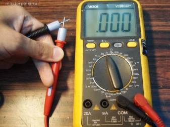
We set the multimeter to the dialing mode and touch the probes to the terminals of the capacitor. We carefully observe the numbers on the scoreboard. They should increase as the capacitor charges.


As soon as I touched the pins, the multimeter immediately showed this value

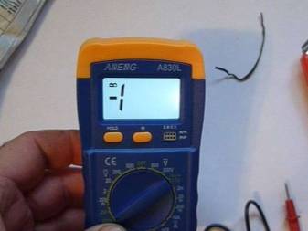
in half a second

and then the value went out of range, and the multimeter showed one.

So what can be said? At the very initial moment of time, a fully discharged capacitor behaves like a conductor. As it is charged with current from the multimeter, its resistance increases until it becomes very large. Once the capacitor is charging, it means it is working. Everything is logical.
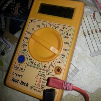
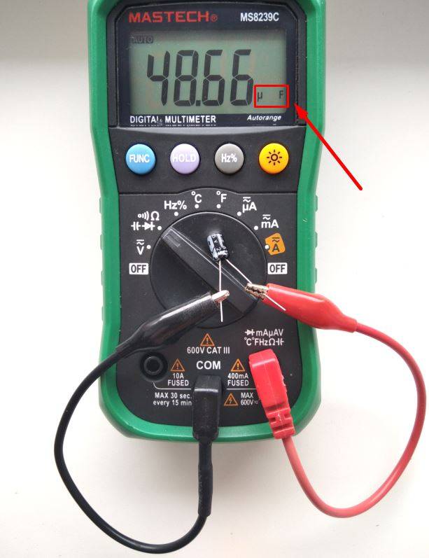
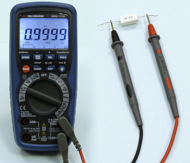
Capacitors of smaller capacity and non-polar capacitors with the help of continuity can only ring for a short circuit between its plates. Therefore, another iron method is used here. Just measure the capacitance of the capacitor). Here I measured the capacitance of the capacitor, which was written 47 microfarads. The multimeter showed 48 microfarads. Or the error of a capacitor, or a multimeter. Since Mastech multimeters are considered quite good, we will write off the error of the capacitor).
And if not in the outlet.
Usually, all studies of household electrical networks, as already mentioned, are conducted through accessible points - sockets and switches. But at times it becomes necessary to check the wiring parameters, where sockets have not yet been installed (dismantled), or for some reason this is inconvenient / impossible. A good example is new buildings with “construction repairs”, where the wiring is only brought into the apartment and there are no electrical appliances, except for the meter, at all.
If you need to know how to check the voltage in the 220 V network with a multimeter and at the same time get the correct data, it is important to remember:
- the easiest way is to check the data in those places where it is planned to install sockets or they have already been removed - there are two wires here, when connected to which the required characteristic is found out;
- confusing the probes is not a problem. If the polarity is wrong, the display will show the voltage value with the “-” sign;
- the main safety rule is not to touch the metal parts of the probes with bare skin when they come into contact with the socket / wiring, do not connect the probes in this position.
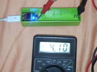
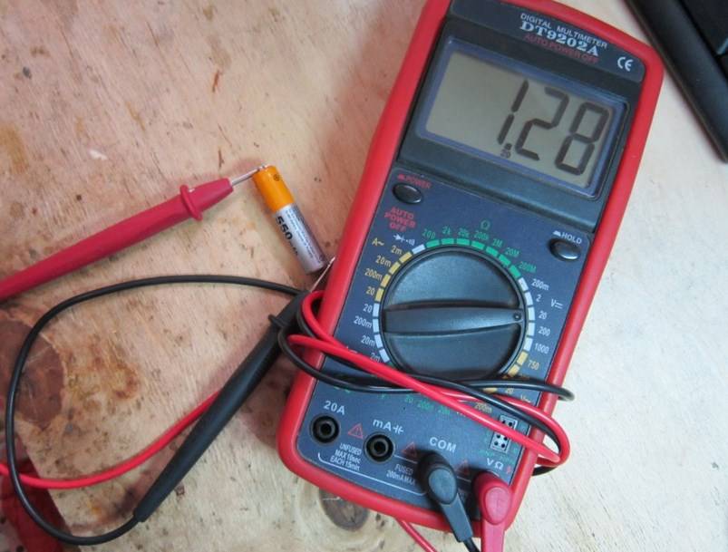
Often beginners also ask how to check the battery voltage (on the battery) with a multimeter
In this case, the procedure is similar, but you should take into account:
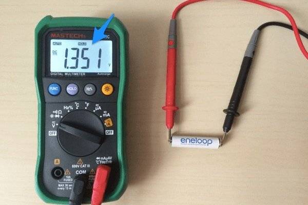
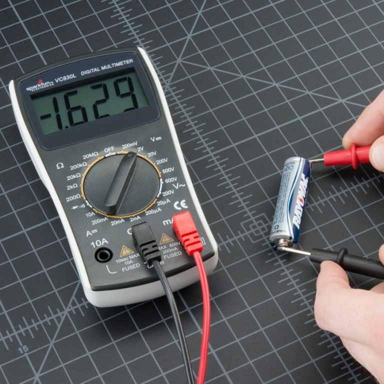
- different characteristics of the mains and battery - unlike household wiring, the current in the battery is constant. Therefore, the regulator of the device is set to the area marked DCV (V-);
- compared to the network, the battery voltage is much lower - 1.5 ... 24 V. Therefore, there is no need to set the regulator to the maximum value of the measured range;
- the polarity of the probes also does not matter, but it is still easier to connect the red (positive) contact to the positive battery output, and the negative (black) contact, respectively, to the negative one.
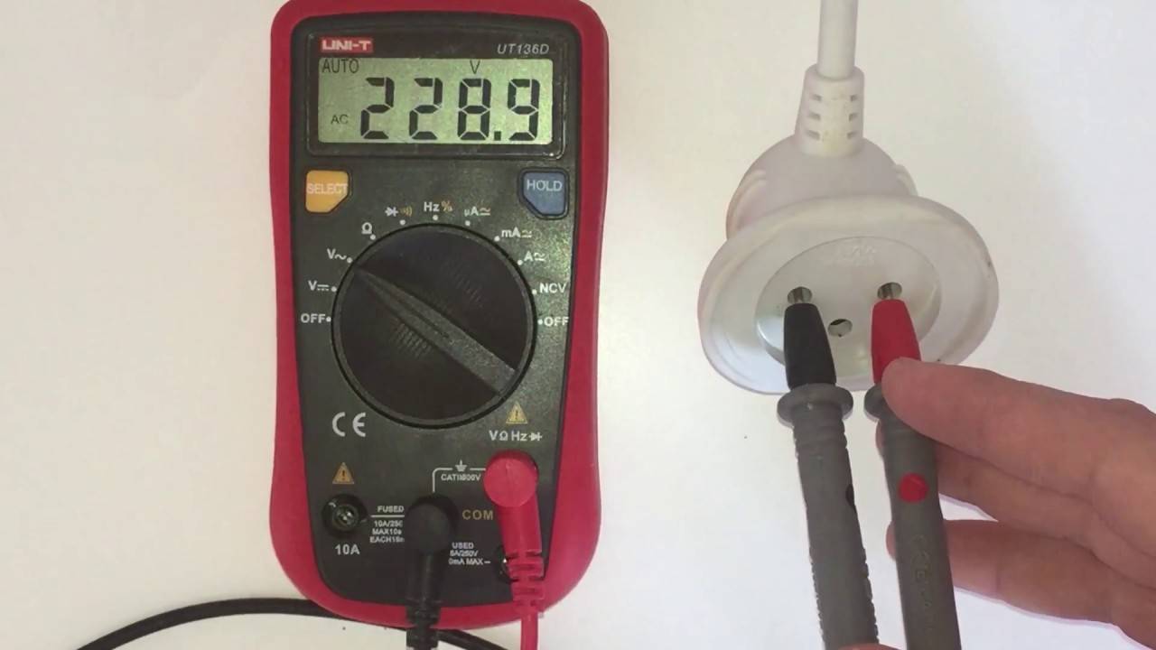
How to check the voltage in the outlet with a multimeter
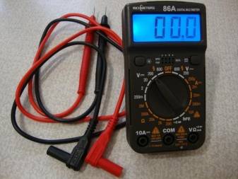
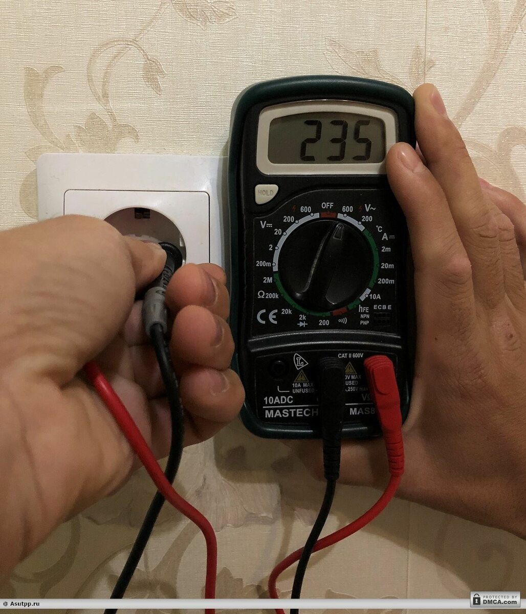
To make any measurements, you must first connect the measuring probes to the device. They are usually two colors - one red, the other black. Black, as a rule, is a zero, common or negative probe, so it is connected to the lowest connector marked COM. The second, red, is connected to the average for almost all measurements. The top connector is for the red probe when measuring AC current up to 10 A.
Next, select the operating mode by turning the round switch to the desired position. If it is known for sure what value the measured parameter should be, then the measurement limit is set a little higher. This is done so as not to burn the device. But there may be a situation where there are no assumptions about what the device can show. Then the measurement limit is set to the maximum possible.
After that, the device is connected to the circuit. If voltage is measured, then in parallel, if current - in series. The measurement of resistance parameters or semiconductors is carried out in the absence of power in the measured circuit.Next, take readings.
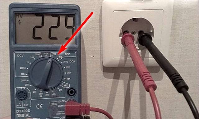
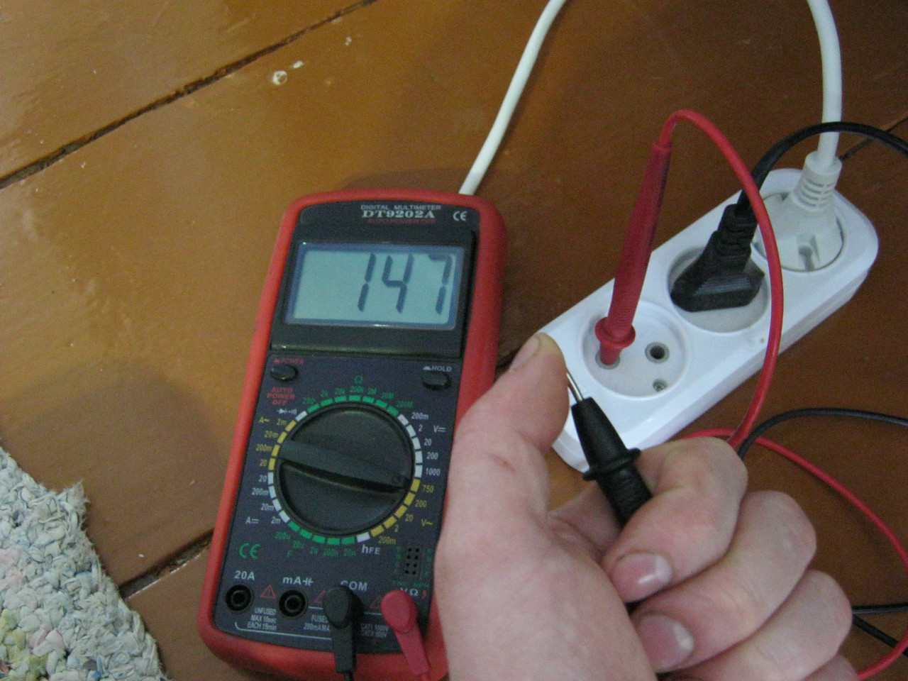
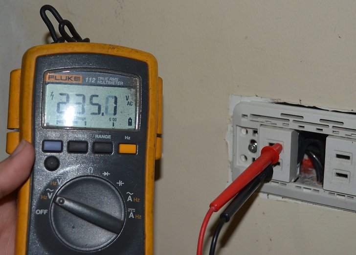
How to check the voltage in a 220V network with a multimeter? Move the switch to the ACV position to the limit of 750 V and take a measurement. How to check the voltage in a 380V network with a multimeter? Similar. It must be remembered that such electricity is life-threatening, and be careful.
External structure and functions
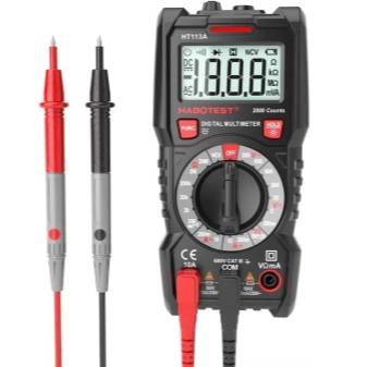
Recently, specialists and radio amateurs mainly use electronic models of multimeters. This does not mean that arrows are not used at all. They are indispensable when, due to strong interference, electronic ones simply do not work. But in most cases we are dealing with digital models.
There are different modifications of these measuring instruments with different measurement accuracy, different functionality. There are automatic multimeters in which the switch has only a few positions - they choose the nature of the measurement (voltage, resistance, current strength) and the device chooses the measurement limits itself. There are models that can be connected to a computer. They transfer measurement data directly to a computer, where they can be saved.
Automatic multimeters on the scale have only types of measurements
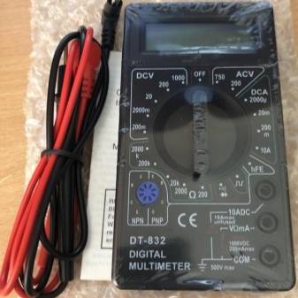
But most home masters use inexpensive models of the middle class of accuracy (with a 3.5 bit depth, which provides an accuracy of readings of 1%). These are common multimeters dt 830, 831, 832, 833. 834, etc. The last digit shows the "freshness" of the modification. Later models have wider functionality, but for home use, these new features are not critical. Working with all these models is not much different, so we will talk in general about the techniques and procedures.


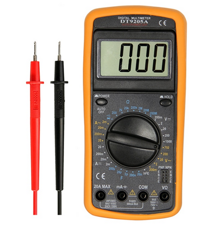
The structure of the electronic multimeter
Before using a multimeter, we will study its structure. Electronic models have a small LCD screen that displays the measurement results. There is a range switch below the screen. It rotates around its own axis. The part on which the red dot or arrow is applied indicates the current type and range of measurements. There are marks around the switch that indicate the type of measurements and their range.
General device of the multimeter
Below on the body there are sockets for connecting probes. Depending on the model of sockets, there are two or three, there are always two probes. One positive (red), the second negative - black. The black probe is always connected to a connector labeled "COM" or COMMON, or which is labeled "ground". Red - to one of the free nests. If there are always two connectors, there are no problems, if there are three sockets, you need to read the instructions for what measurements to insert the “positive” probe into which socket. In most cases, the red probe is connected to the middle socket. This is how most measurements are made. The upper connector is necessary if you are measuring a current up to 10 A (if more, then also in the middle socket).
Where to connect multimeter leads
There are tester models in which the sockets are located not on the right, but at the bottom (for example, the Resant DT 181 multimeter or Hama 00081700 EM393 in the photo). There is no difference when connecting in this case: black to the socket with the inscription “COM”, and red according to the situation - when measuring currents up to 200 mA to 10 A - to the rightmost socket, in all other situations - to the middle one.
Sockets for connecting probes on multimeters can be located below
There are models with four connectors.In this case, there are two sockets for measuring current - one for microcurrents (less than 200 mA), the second for current strength from 200 mA to 10 A. Having understood what is in the device and why, you can begin to figure out how to use a multimeter.
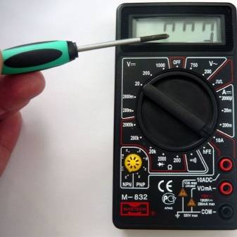
Switch position
The measurement mode depends on the position of the switch. There is a dot on one of its ends, it is usually tinted with white or red. This end indicates the current mode of operation. In some models, the switch is made in the form of a truncated cone or has one pointed edge. This sharp edge is also a pointer. To make it easier to work, you can apply bright paint to this pointing edge. It can be nail polish or some kind of abrasion resistant paint.
The position of the measuring range switch on the multimeter
By turning this switch you change the operating mode of the device. If it stands vertically upwards, the device is switched off. In addition, there are the following provisions:
- V with a wavy line or ACV (to the right of the "off" position) - AC voltage measurement mode;
- A with a straight line - DC current measurement;
- A with a wavy line - definition of alternating current (this mode is not available on all multimeters, it is not on the photos presented above);
- V with a straight line or the inscription DCV (to the left of the off position) - for measuring direct voltage;
- Ω - resistance measurement.
There are also provisions for determining the gain of transistors and determining the polarity of diodes. There may be others, but their purpose must be sought in the instructions for a particular device.
Peculiarities
The device in question combines several devices at once, connecting in different ways to one section of the circuit.In order to use it correctly and get a complete picture of the state of the electrical network or a separate outlet, you should know at least some theory. At a minimum, you should understand how you can measure the voltage, and what exactly - the strength of the current, and how you can correctly connect one or another device.
When the cables are connected to a working power source, they receive an electrical voltage measured between zero and phase. To put it simply, it is" - + "and" - ". The voltage in a standard electrical network can be measured both without a load connected to the electrical network, and with it.
But the current itself appears only when the circuit is closed. Only after that does it begin to strive to move between the poles. In this case, measurements should be carried out only when the device is connected in series. To measure the magnitude of the current, you must first let it pass through the multimeter.
In order for the multimeter itself not to distort the current strength and display the most accurate data, its resistance must be minimized. If it is set to the current measurement mode, and at the same time try to measure the voltage with it, then the result of this will be a simple short circuit. Although modern models do not have this problem, voltage and current measurements are made by the same terminal connection. But it will not be superfluous to recall some knowledge from the course of physics. According to them, the same voltage will be observed in sections of the electrical circuit connected in parallel, and the current will be the same only when the conductor connection is in series.
In order to avoid errors and inaccuracies, before starting measurements, you should analyze the markings that the contacts of the multimeter and mode switch have.Note that in domestic conditions, several groups of electrical networks are used. The most common system in modern homes will be a system where there is a voltage of 220 volts at a frequency of 50 hertz. Usually it consists of two elements - zero and phase. And the socket itself plays the role of an output.
In recent years, in new-built houses, a different power supply scheme has been installed - a three-phase one. Its difference will be a higher voltage at a level of 380 volts. This makes it possible to power more powerful devices that do not work correctly in traditional systems. At least for this reason, the rated voltage should be measured in the outlet in order to simply understand whether it is possible to connect some kind of powerful device to the sockets and the possibility of wiring to withstand the load created by the device.
In addition, voltage measurement will be required in other cases:
- if you want to check the operation of the power cables;
- if it is necessary to check the operability of the switch or socket;
- if the light in the chandelier does not light up, although it is known that it is operational.
The ability to independently use a multimeter will be a great opportunity to save on calling a wizard.
How to measure 220 with a multimeter
 Multimeters are used for measurement. They are of two types:
- Pointer or analog. Such models were used before the advent of electronic ones. They are inexpensive, not demanding in operation and do not require a DC source. The disadvantage of the device is the inconvenience of taking readings due to the size of the scale.
- Electronic or digital. These are modern convenient devices with a lot of functions. They are more expensive, but the readings are more accurate.Most professionals use this type of device.
- constant and alternating voltage;
- resistance;
- capacitive and frequency characteristics;
- strength of direct and alternating current;
- parameters of diodes and transistors;
- temperature regime.
Switching modes is done using the knob on the device panel.
 Work algorithm:
- Before starting work, the device is assembled. A black probe is always inserted into the connector marked COM. Red must be connected to the connector labeled VΩmA. There is a third output of 10 A, which means that the multitester is able to measure current up to the specified value.
- After connecting, the measurement mode is selected. It must be set carefully, as if the settings are incorrect, the device may fail. Changing the position of the switch during operation is prohibited. The rotary switch is set in the ACV or V field to position 750.
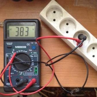
- Now the probes can be inserted into the socket sockets and see the result. A value of 220 V will have deviations, according to GOST, the error reaches 10%. If the value is outside the error, it is recommended to install a voltage stabilizer at home.
How to check the voltage in the outlet with a multimeter - step by step instructions
If any of the household appliances does not turn on, then before diagnosing it and checking the entire electrical / wiring circuit, you should make sure that there is / is no power supply. Even if the light in the room is on, this does not mean that there is voltage in a single outlet. You can verify this (or the opposite) using a special indicator probe (probe) or a multimeter.The latter device is even better, as it allows you to determine the numerical value of this parameter of the intra-house network.


If you check the voltage in the outlet with a simple multimeter, you can make sure that the voltage rating is within tolerance, whether it is enough for the correct operation of technical devices.
Basic principles of current measurement
The main feature of working with a multitester in ammeter mode is that it must be included in the open circuit. Such a connection is called serial. In fact, the device becomes part of this circuit, that is, all current must pass through it. And as you know, the current strength in any part of an unbranched electrical circuit is constant. Simply put, how much "entered" as much due and "exit". That is, the place of the serial connection of the ammeter does not really matter.
To make it clearer, below is a diagram that shows the difference in connecting a multimeter in different operating modes.
Differences in the principles of connecting a multitester in different measurement modes
- So, when measuring the current strength, the multimeter is included in the circuit break, itself becoming one of its links. That is, there will be a problem of how to organize this chain break in practice. They decide differently - this will be shown below.
- When measuring voltage (in voltmeter mode), the circuit, on the contrary, does not break, and the device is connected in parallel with the load (the section of the circuit where you want to know the voltage). When measuring the voltage of the power source, the probes are connected directly to the terminals (socket contacts), that is, the multimeter itself becomes a load.
- Finally, if the resistance is measured, then the external power supply does not figure at all.The contacts of the device are connected directly to a particular load (the ringed section of the circuit). The required current for measurements comes from an independent power source of the multitester.
Let's return to the topic of the article - to measure the current strength.
It is very important to initially correctly set the measurement range on the multimeter, in addition to direct or alternating current. I must say that beginners often have problems with this.
Current strength is a very misleading value. And “burning” your device, or even doing big trouble by incorrectly setting the upper limit of measurements, is as easy as shelling pears.
Start measuring the current strength, especially if there is no idea about its possible value in the circuit, should be from the maximum range of the multitester. If necessary, it is possible, by rearranging the wire and successively lowering the upper limit, to reach the optimal one.
Therefore, a strong recommendation - if you do not know how much current is expected in the circuit, always start measurements from the maximum values. That is, for example, on the same DT 830, the red probe must be installed in the 10 amp socket (shown in the illustration with a red arrow). And the mode switch knob should also show 10 amps (blue arrow). If the measurements show that the limit is too high (readings are less than 0.2 A), then you can, in order to get more accurate values, first move the red wire to the middle socket, and then the switch knob to the 200 mA position. It happens that this is too much, and you have to reduce the switch by another discharge, etc. Not quite convenient, we do not argue, but it is safe for both the user and the device.
Speaking of security
Safety precautions should never be neglected.And especially when it comes to dangerous voltages (and the mains voltage of 220 V is extremely dangerous) and high currents
We are calmly talking about amperes here, but meanwhile, a current no higher than 0.001 amperes is considered safe for humans. And a current of only 0.01 amperes, passing through the human body, most often leads to irreversible consequences.
Current measurements, especially if the work is carried out in the highest range, are recommended to be carried out as quickly as possible. Otherwise, the multitester may simply burn out.
By the way, warning labels near the socket for connecting the measuring wire can also inform about this.
Example of a warning label at the wire connection socket for measurements on the maximum permissible current range
Note. The word "unfused" in this case means that the device in this mode is not protected by a fuse
That is, if it overheats, it will simply fail completely. The allowable measurement time is also indicated - no more than 10 seconds, and even then no more than once every 15 minutes ("each 15 m"). That is, after each such measurement, you will also have to withstand a considerable pause.
In fairness, not all multimeters are so “finicky”. But if there is such a warning, you should not neglect it. And in any case, measure the current strength as quickly as possible.
Socket current measurement
Never, under any circumstances, measure the AC current of an outlet with a multitester directly, without a connected load. If you just stick two probes from the tester into the outlet, you can say goodbye to the device. As a result, we get a "New Year's fireworks" and a burned-out electrical measuring device.
The current strength in the socket is necessarily measured with the load connected in series in the tester-socket circuit. Even an ordinary light bulb with a cartridge (the place where the lamp is screwed in) can act as an elementary load.
To correctly measure the current strength in the circuit, we switch the trigger to the maximum position of the “A ~” section, in the presented device this value is 20 Amperes. We rearrange the red probe into the connector with the inscription "20A" (UNFUSED - mode without a fuse, FUSED - mode with a fuse)
Having connected the tester and the light bulb in series, we insert one of the probes into the socket, we connect one wire from the bulb base to the other probe. We insert the second wire of the light bulb into the free hole of the socket. We take the values of the current strength. It is not recommended to measure more than 15 seconds in time.
And yet, the current strength is not recommended to be measured in the outlet. It does not carry any semantic load. The household power supply simply has a maximum limit in amps that must be respected. The current strength always exists only in the presence of a load, where we measure the current.


Conclusion
If, nevertheless, difficulties arise, how to check the voltage in the outlet with a multimeter, then the instructions for the device give a detailed description of this. I am glad that such devices have an acceptable price.
9 Famous Women Who Have Fallen In Love With Women Showing interest in someone other than the opposite sex is not unusual. You can hardly surprise or shock someone if you admit it.
Unforgivable Movie Mistakes You Probably Never Noticed There are probably very few people who don't like watching movies. However, even in the best cinema there are errors that the viewer can notice.
20 photos of cats taken at the right moment Cats are amazing creatures, and perhaps everyone knows about it. They are also incredibly photogenic and always know how to be at the right time in the rules.
10 Adorable Celebrity Kids Who Look Very Different Today Time flies and one day little celebrities become unrecognizable adults Pretty boys and girls turn into s.
11 Weird Signs That You're Good in Bed Do you also want to believe that you're giving your romantic partner pleasure in bed? At least you don't want to blush and apologize.
7 body parts you shouldn't touch Think of your body as a temple: you can use it, but there are some sacred places that you shouldn't touch with your hands. Display research.


