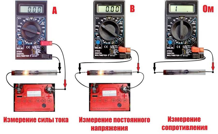
- We check the capacitor with a multimeter in ohmmeter mode
- How to check the multimeter for performance
- Check progress
- How to check the device without desoldering
- Chip check
- Features of SMD Capacitors
- Checking the capacitor with a multimeter
- How to test a capacitor
- Determining the capacitance of an unknown capacitor
- Method number 1: capacitance measurement with special devices
- Method number 2: measuring the capacitance of two capacitors in series
- Method number 3: measuring capacitance through the time constant of the circuit
- Other ways to measure capacitance
- Checking procedure
- Visual inspection
- Checking the reliability of fixation
- Resistance test
- per container
- Helpful Hints
- Checking with testers
- Capacity
- Voltage
- Resistance
- How does a capacitor work and why is it needed
- How to test a capacitor with a multimeter
- Electrolytic
- Ceramic
- Film
- Control button block: measurement tasks
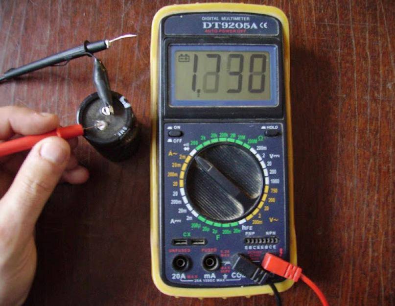
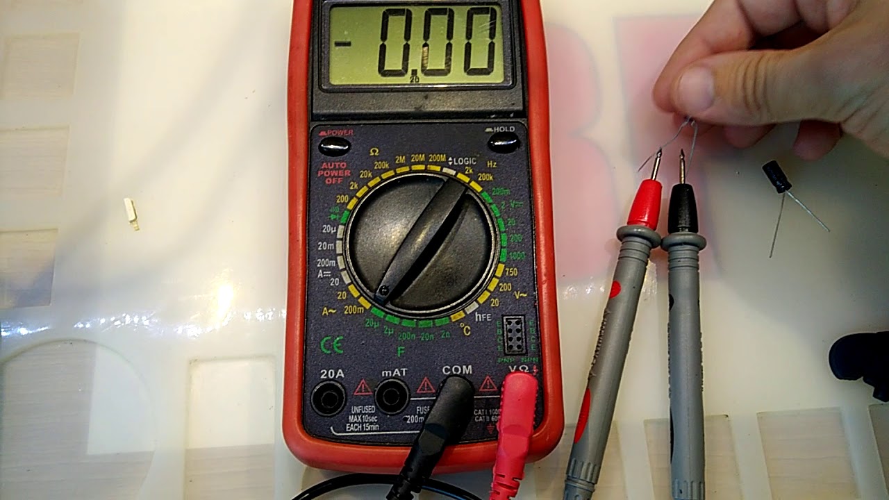
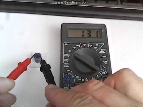
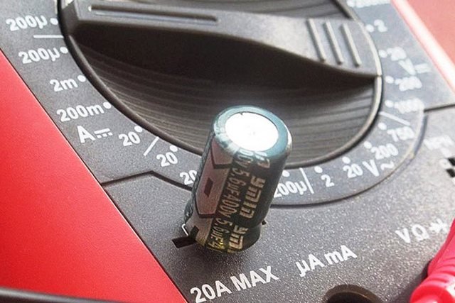
We check the capacitor with a multimeter in ohmmeter mode
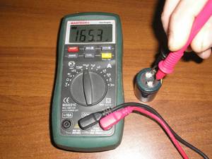
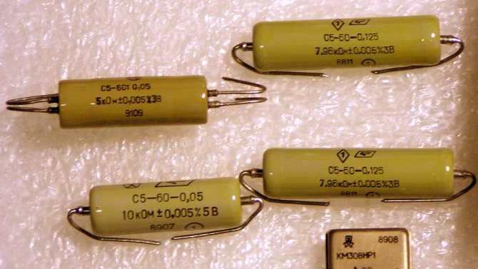
For example, we will test four capacitors ourselves: two polar (dielectric) and two non-polar (ceramic).
But before checking, we must necessarily discharge the capacitor, while it is enough to close its contacts with any metal.
In order to switch to the resistance (ohmmeter) mode, we move the switch to the resistance measurement group in order to establish the presence of an open or short circuit.
So, first of all, let's check the polar air conditioners (5.6 uF and 3.3 uF) previously installed near non-working energy-saving light bulbs
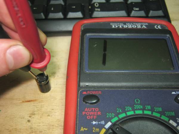
We discharge the capacitors by closing their contacts with a conventional screwdriver. You can use any other metal object that is convenient for you. The main thing is that the contacts fit snugly to it. This will allow us to get accurate instrument readings.
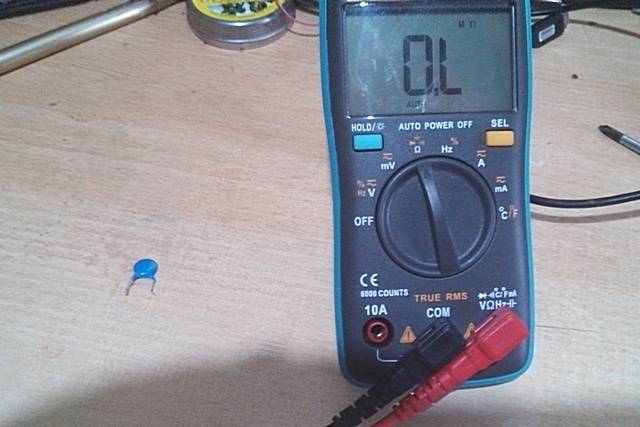
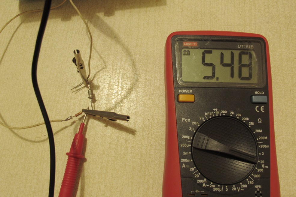
The next step is to set the switch to the 2 MΩ scale and connect the contacts of the capacitor and the probes of the device. Next, we observe on the display quickly dodging resistance parameters.
You ask me what is the matter and why do we see “floating indicators” of resistance on the display? This is quite simple to explain, since the power supply of the device (battery) has a constant voltage and due to this, the capacitor is charged.
Over time, the capacitor accumulates more and more charge (is charged), thereby increasing the resistance. The capacitance of the capacitor affects the charging speed. As soon as the capacitor is fully charged, its resistance value will correspond to the value of infinity, and the multimeter on the display will show "1". These are the parameters of the working capacitor.
There is no way to show the picture in the photo. So for the next instance with a capacity of 5.6 microfarads, the resistance indicators start at 200 kOhm and gradually increase until they overcome the 2 MΩ indicator. This procedure does not take more than -10 sec.
For the next capacitor with a capacity of 3.3 uF, everything happens in the same way, but the process takes less than 5 seconds.
You can check the next pair of non-polar capacitors in the same way by analogy with the previous capacitors. We connect the probes of the device and contacts, monitor the state of resistance on the display of the device.
Consider the first "150nK". At first, its resistance will decrease slightly to about 900 kOhm, then its gradual increase to a certain level follows. The process takes 30 seconds.
At the same time, on the multimeter of the MBGO model, we set the switch to a scale of 20 MΩ (the resistance is decent, charging is very fast)
The procedure is classic, we remove the charge by closing the contacts with a screwdriver:
We look at the display, tracking the resistance indicators:
We conclude that as a result of the check, all the presented capacitors are in good condition.
How to check the multimeter for performance
 It is necessary to move the switch to the position for measuring resistance. Usually this position is designated OHM. The device should be calibrated with a mechanical graduation so that the arrow is aligned with the extreme risk.
Close the tails with a screwdriver, a knife, one of the tentacles of the multimeter to remove the charge from the capacitor
At this stage, you must act carefully and carefully. Even a small household item can strike the human body
After turning on the device, it is necessary to switch the switch to the resistance measurement mode and connect the probes. The display should show zero resistance or close to it.


Check progress
Determined visually for physical disorders. Then they try to mount the legs on the board. Slightly swing the element in different directions.If one of the legs breaks or the electrical track on the board is peeled off, this will be immediately noticeable.
If there are no external signs of violations, then they reset the possible charge and call with a multimeter.
If the device shows almost zero resistance, then the element has begun to charge and is working. As you charge, the resistance starts to rise. The growth of the value should be smooth, without jerks.
In case of malfunction:
- When clamping the connectors, the tester readings are immediately dimensionless. So, a break in the element.
- Zero multimeter. Sometimes it gives an audible signal. This is a sign of a short circuit or, as they say, "breakdown".
In these cases, the element must be replaced with a new one.
 If you need to check the performance of a non-polar capacitor, then choose the measurement limit of the megaohm. During testing, a working radio component will not show resistance above 2 mΩ. True, if the nominal charge of the element is less than 0.25 microfarads, then an LC meter is required. A multimeter won't help here.
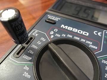
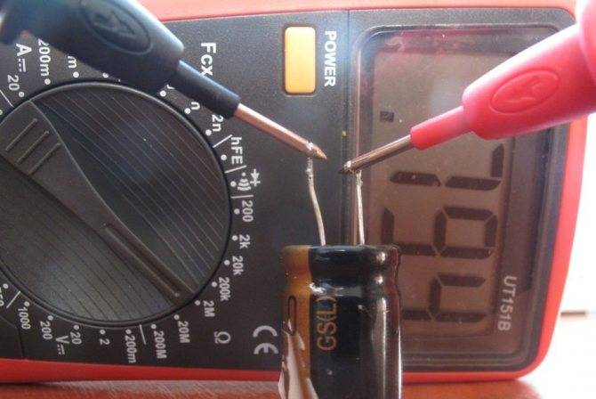
The resistance test is followed by the capacitance test. In order to know whether the radio element is capable of accumulating and holding a charge.
The multimeter toggle switch is switched to CX mode. The measurement limit is selected based on the capacity of the element. For example, if a capacitance of 10 microfarads is indicated on the case, then the limit on the multimeter can be 20 microfarads. The capacity value is indicated on the case. If the measurement indicators are very different from the declared ones, then the capacitor is faulty.
This type of measurement is best done with a digital instrument. The arrow will show only a quick deviation of the arrow, which only indirectly indicates the normality of the checked element.
How to check the device without desoldering
In order not to accidentally burn any microcircuit on the board with a soldering iron, there is a way to check the capacitor with a multimeter without soldering.
Before ringing, the electrical components are discharged. After that, the tester is switched to the resistance test mode. The tentacles of the device are connected to the legs of the element being checked, observing the required polarity. The arrow of the device should deviate, because as the element charges, its resistance increases. This indicates that the capacitor is good.
Sometimes you have to check on the board and microcircuits. This is a complex procedure, not always feasible. Since the microcircuit is a separate unit, inside of which there are a large number of micro-details.
Chip check
The multimeter is put into voltage measurement mode. A voltage is applied to the input of the microcircuit within the permissible range. After that, it is necessary to control the behavior at the output of the microcircuit. This is a very difficult call.
Before performing all types of work related to electricity, checking, testing radio elements, it is very important to follow the safety rules. The multimeter should only test a de-energized electrical board
Features of SMD Capacitors
Modern technologies allow making radio components of very small sizes. With the use of SMD technology, circuit components have become miniaturized. Despite their small size, testing SMD capacitors is no different from larger ones. If you need to find out if it is working or not, you can do it right on the board. If you need to measure the capacitance, you need to solder it, then take measurements.

SMD technology allows you to make miniature radio elements
The performance test of an SMD capacitor is carried out in the same way as electrolytic, ceramic and all others. Probes need to touch the metal leads on the sides. If they are filled with varnish, it is better to turn the board over and test it “from the back”, determining where the conclusions are.
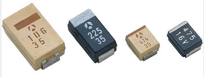
Tantalum SMD capacitors can be polarized. To indicate the polarity on the case, on the side of the negative terminal, a strip of a contrasting color is applied
Even the designation of a polar capacitor is similar: a contrasting stripe is applied on the case near the “minus”. Only tantalum capacitors can be polar SMD capacitors, so if you see a neat rectangle on the board with a strip along the short edge, apply a multimeter probe to the strip that is connected to the negative terminal (black probe).


Checking the capacitor with a multimeter
To begin with, let's figure out what kind of device it is, what it consists of, and what types of capacitors exist. A capacitor is a device that can store an electrical charge. Inside it consists of two metal plates parallel to each other. Between the plates is a dielectric (gasket). The larger the plates, the correspondingly more charge they can accumulate.
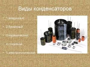
There are two types of capacitors:
- 1) polar;
- 2) non-polar.
As you might guess from the name, polar ones have polarity (plus and minus) and are connected to electronic circuits with strict observance of polarity: plus to plus, minus to minus. Otherwise, the capacitor may fail. All polar capacitors are electrolytic.There are both solid and liquid electrolytes. The capacitance ranges from 0.1 ÷ 100000 uF. Non-polar capacitors do not matter how to connect or solder into the circuit, they have no plus or minus. In non-polar conders, the dielectric material is paper, ceramics, mica, glass.
It will be interesting How to check the varistor with a multimeter?
Their capacitance is not very large, ranging from a few pF (picofarads) to units of microfarads (microfarads). Friends, some of you may wonder why this unnecessary information? What is the difference between polar and non-polar? All this affects the measurement technique. And before you check the capacitor with a multimeter, you need to understand what type of device is in front of us.
How to test a capacitor
Sometimes a malfunction of an electrolytic capacitor is detected without verification - by swelling or rupture of the top cover. It is intentionally weakened by a cross-shaped notch and works as a safety valve, rupturing at a slight pressure. Without this, the gases released from the electrolyte would rupture the capacitor case with splashing of the entire contents.
But violations may not appear outwardly. Here's what they are:
- Due to chemical changes, the capacity of the element has decreased. For example, capacitors with liquid electrolyte dry out, especially at high temperatures. Because of this feature, there are restrictions on the operating temperature for them (the permissible range is indicated on the case).
- An output break has occurred.
- Conductivity appeared between the plates (breakdown). Actually, it exists and is in good condition - this is the so-called leakage current. But upon breakdown, this value turns from scanty to significant.
- The maximum allowable voltage has decreased (reversible breakdown). For each capacitor there is a critical voltage that causes a short circuit between the plates. It is indicated on the body. In the case of a decrease in this parameter, the element behaves as if it is serviceable during testing, because the testers supply low voltage, but in the circuit it is broken.
The most primitive way to test a capacitor is for a spark. The element is charged, then the terminals are closed with a metal tool with an insulated handle. It is advisable to wear rubber gloves on your hands. A serviceable element is discharged with the formation of a spark and a characteristic crackle, a non-working element is sluggish and imperceptible.
This method has two drawbacks:
- danger of electrical injury;
- uncertainty: even in the presence of a spark, it is impossible to understand whether the actual capacitance of the radio component corresponds to the nominal capacitance.
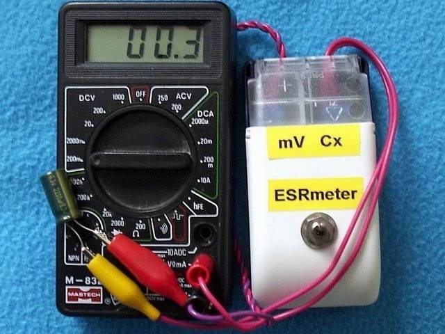
A more informative check using a tester. It is best to use a special - LC-meter. It is designed to measure capacitance, and is designed for a wide range. But a regular multimeter will also tell a lot about the state of the capacitor.
Determining the capacitance of an unknown capacitor
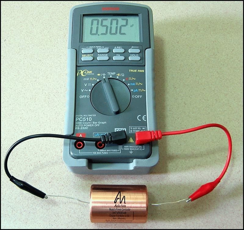
Method number 1: capacitance measurement with special devices
The easiest way is to measure capacitance with a capacitance measuring instrument. This is already clear, and this was already mentioned at the beginning of the article and there is nothing more to add.
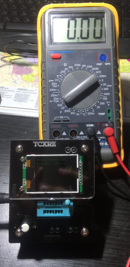
If the devices are completely dull, you can try to assemble a simple home-made tester. On the Internet you can find good schemes (more complicated, simpler, very simple).
Well, or fork out, finally, for a universal tester that measures capacitance up to 100,000 microfarads, ESR, resistance, inductance, allows you to check diodes and measure transistor parameters. How many times has he rescued me!
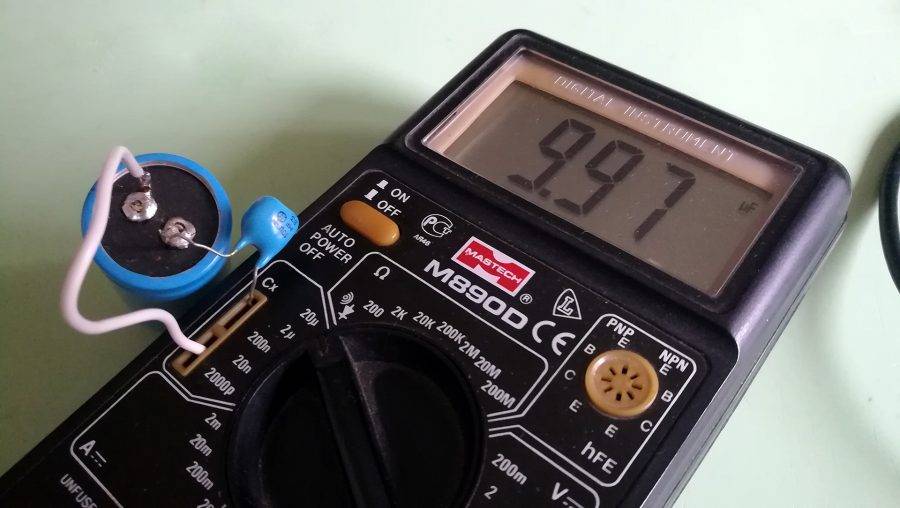
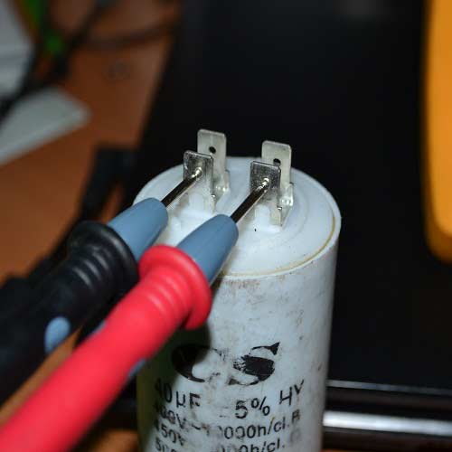
Method number 2: measuring the capacitance of two capacitors in series
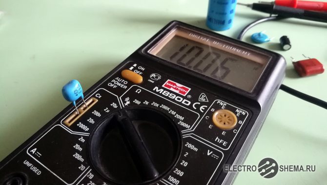
Sometimes it happens that there is a multimeter with a capacitance gauge, but its limit is not enough. Usually the upper threshold of multimeters is 20 or 200 uF, and we need to measure the capacitance, for example, at 1200 uF. How then to be?
The formula for the capacitance of two series-connected capacitors comes to the rescue:
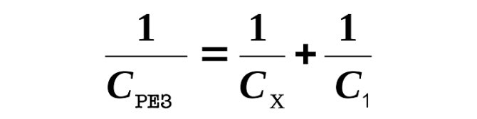
The bottom line is that the resulting capacitance Ccut of two capacitors in series will always be less than the capacitance of the smallest of these capacitors. In other words, if we take a 20 uF capacitor, then no matter how large the capacitance of the second capacitor is, the resulting capacitance will still be less than 20 uF.
Thus, if the measurement limit of our multimeter is 20 uF, then the unknown capacitor must be in series with the capacitor no more than 20 uF.
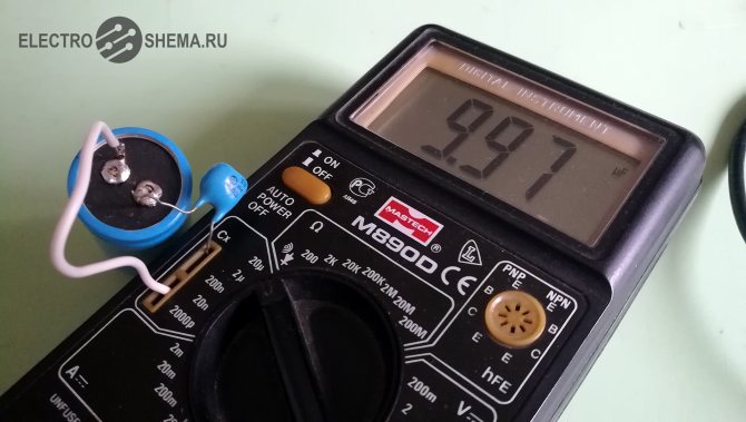
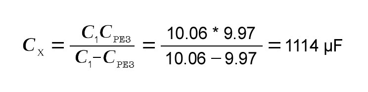
It remains only to measure the total capacitance of the chain of two capacitors connected in series. The capacitance of an unknown capacitor is calculated by the formula:
For example, let's calculate the capacitance of a large capacitor Cx from the photo above. To carry out the measurement, a 10.06 uF capacitor C1 is connected in series with this capacitor (it was previously measured). It can be seen that the resulting capacitance was Cres = 9.97 μF.
We substitute these numbers into the formula and get:
Method number 3: measuring capacitance through the time constant of the circuit
As you know, the time constant of an RC circuit depends on the value of the resistance R and the value of the capacitance Cx: The time constant is the time it takes for the voltage across the capacitor to decrease by a factor of e (where e is the base of the natural logarithm, approximately equal to 2.718).
Thus, if you detect how long the capacitor will discharge through a known resistance, it will not be difficult to calculate its capacitance.
To improve the measurement accuracy, it is necessary to take a resistor with a minimum resistance deviation. I think 0.005% will be fine =)


Although you can take a regular resistor with a 5-10% error and stupidly measure its real resistance with a multimeter. It is desirable to choose a resistor such that the discharge time of the capacitor is more or less sane (10-30 seconds).
Here's a guy who said it really well in a video:
Other ways to measure capacitance
It is also possible to very roughly estimate the capacitance of a capacitor through the growth rate of its resistance to direct current in the continuity mode. This was already mentioned when it was about checking for a break.
The brightness of the light bulb (see short circuit search method) also gives a very rough estimate of the capacitance, but nevertheless, this method has the right to exist.
There is also a method for measuring capacitance by measuring its AC resistance. An example of the implementation of this method is the simplest bridge circuit:
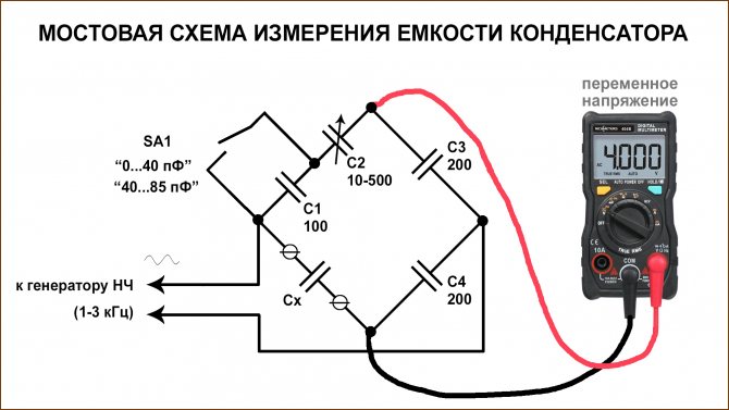
By rotating the rotor of the variable capacitor C2, the balance of the bridge is achieved (balancing is determined by the minimum voltmeter readings). The scale is pre-calibrated in terms of capacitance of the measured capacitor. Switch SA1 is used to switch the measuring range.The closed position corresponds to a scale of 40...85 pF. Capacitors C3 and C4 can be replaced with the same resistors.
The disadvantage of the circuit is that an alternating voltage generator is required, plus pre-calibration is required.
Checking procedure
Some defects can be detected without the device. Therefore, before using it, you must complete the first 2 points.
Visual inspection
Even a slight swelling of the case is a clear sign of a malfunction. Other defects that are easy to detect visually:
- the appearance of leaks (typical for "electrolytes");
- changing the color of the hull;
- the presence of signs of thermal effects in this area (detachment of tracks, darkening of the board, etc.).
Checking the reliability of fixation
You need to try to shake the container if it is soldered to the electronic board. Naturally, carefully. When one of the legs breaks, you will immediately feel it.
Resistance test
If you have to work with the "electrolyte", then its polarity is important here. The positive terminal is indicated on the body with a “+” label. Therefore, the terminals of the device are connected accordingly. Plus - to "+", minus - to "-". But this is for "electrolytes". When checking capacitors paper, ceramic, and so on - no difference. The measurement limit is the maximum.
What to watch? How does the arrow move? Depending on the value of the capacitor, it will either immediately rush to "∞", or slowly go to the edge of the scale. But the main thing is that when it is moved, there should be no jumps (jerks).
- If there is a breakdown (short circuit) in the part, then the arrow will remain at zero.
- With an internal cliff, it will abruptly go to "infinity".
per container
In this case, you will need a digital device.It is worth noting that not all multimeters are able to carry out such a test, and if they can, then the result will be quite approximate. At the very least, you shouldn't rely too much on "made in China" products.
How to connect the part to the device is written in its instructions (section "Capacity measurement"). If we are talking about the "electrolyte", then again - with the observance of polarity.
Approximately it is possible to determine the compliance with the capacity rating indicated on the part body with a pointer device. If it is small, then when checking for resistance, the arrow deviates quickly enough, but not sharply. With a significant capacitance, the charge proceeds more slowly, and this is clearly visible. But again, this is just indirect evidence of the suitability of the capacitor, indicating that there is no short circuit and it takes a charge. An increased leakage current cannot be determined in this way.
Helpful Hints
If the circuit fails, then you need to pay attention to the release date of the capacitors in a particular circuit. For 5 years, this radio component "dries out" by about 55 - 75%. It makes no sense to waste time on checking the old capacity - it is better to change it right away
Even if the capacitor, in principle, is working, then it already introduces certain distortions. This primarily applies to pulse circuits that can be encountered, for example, when repairing an inverter-type “welder”. And ideally, it is advisable to change such chain elements every couple of years.
In order for the measurement results to be as accurate as possible, a “fresh” battery should be inserted into the device before checking the capacity.
Before testing, the capacitor must be soldered out of the circuit (or at least one of its legs). For large parts with wiring - 1 of them is disconnected.Otherwise, there will be no true result. For example, the chain will "ring" through another section.
During the test of the capacitor, do not touch its terminals with your hands. For example, press the probe to the legs with your fingers. The resistance of our body is about 4 ohms, so it is completely pointless to check the radio component in this way.
It makes no sense to spend time checking the old capacity - it is better to change it right away. Even if the capacitor, in principle, is working, then it already introduces certain distortions. This primarily applies to pulse circuits that can be encountered, for example, when repairing an inverter-type “welder”. And ideally, it is advisable to change such chain elements every couple of years.
In order for the measurement results to be as accurate as possible, a “fresh” battery should be inserted into the device before checking the capacity.
Before testing, the capacitor must be soldered out of the circuit (or at least one of its legs). For large parts with wiring - 1 of them is disconnected. Otherwise, there will be no true result. For example, the chain will "ring" through another section.
During the test of the capacitor, do not touch its terminals with your hands. For example, press the probe to the legs with your fingers. The resistance of our body is about 4 ohms, so it is completely pointless to check the radio component in this way.
Checking with testers
Sequencing:
- We switch the ohmmeter or multimeter to the upper limit of measurements.
- We discharge by closing the central contact (wire) on the case.
- We connect one probe of the measuring device to the wire, the second - to the body.
- The serviceability of the part is indicated by a smooth deviation of the arrow or a change in digital values.
If the value “0” or “infinity” is immediately displayed, it means that the part under test needs to be replaced. During the test, it is impossible to touch the terminals of the energy storage device or the probes of the device connected to them, otherwise the resistance of your body will be measured, and not the element under study.
Capacity
To measure capacitance, you need a digital multimeter with the appropriate function.
Procedure:
- We set the multimeter in the capacitance determination mode (Cx) to the position corresponding to the expected value of the part under study.
- We connect the leads to a special connector or to the probes of the multimeter.
- The display shows the value.
You can also determine the size of the capacitance according to the “small-large” principle on a conventional multimeter. With a small value of the indicator, the arrow will deviate faster, and the larger the “capacity”, the slower the pointer will move.


Voltage
In addition to capacitance, you should check the operating voltage. On a serviceable part, it corresponds to that indicated on the case. To check, you will need a voltmeter or multimeter, as well as a charging source for the element under study with a lower voltage.
We make a measurement on a charged part and compare it with the nominal value
You need to act carefully and quickly, since in the process the charge in the drive is lost and it is important to remember the first digit
Resistance
When measuring resistance with a multimeter or ohmmeter, the indicator should not be in the extreme positions of the measurement. Values of "0" or "infinity" indicate, respectively, a short circuit or open circuit.
Non-polar drives with a capacitance greater than 0.25 uF can be tested by setting the measurement range to 2 MΩ.On a working part, the indicator on the display should be above 2.
How does a capacitor work and why is it needed
A capacitor is a passive electronic radio element. Its principle of operation is similar to a battery - it accumulates electrical energy in itself, but at the same time it has a very fast discharge and charge cycle. A more specialized definition says that a capacitor is an electronic component used to store energy or electric charge, consisting of two plates (conductors) separated by an insulating material (dielectric).
simple capacitor circuit
So what is the principle of operation of this device? On one plate (negative) an excess of electrons is collected, on the other - a deficiency. And the difference between their potentials will be called voltage. (For a strict understanding, you need to read, for example: I.E. Tamm Fundamentals of the Theory of Electricity)
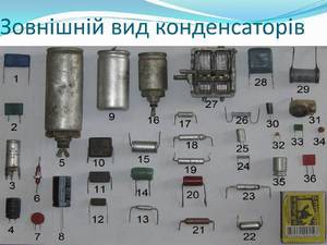
Depending on what material is used for the lining, capacitors are divided into:
- solid or dry;
- electrolytic - liquid;
- oxide-metal and oxide-semiconductor.
According to the insulating material, they are divided into the following types:
- paper;
- film;
- combined paper and film;
- thin-layer;
- …
Most often, the need to check using a multimeter arises when working with electrolytic capacitors.
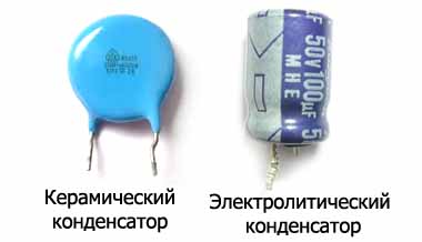
Ceramic and electrolytic capacitor
The capacitance of a capacitor is inversely related to the distance between the conductors, and in direct proportion to their area. The larger and closer they are to each other, the greater the capacity. It is measured using a microfarad (mF).The covers are made of aluminum foil, twisted into a roll. An oxide layer applied to one of the sides acts as an insulator. To ensure the highest capacity of the device, a very thin, electrolyte-impregnated paper is laid between the foil layers. A paper or film capacitor made using this technology is good because the plates separate the oxide layer into several molecules, which makes it possible to create volumetric elements with a large capacity.
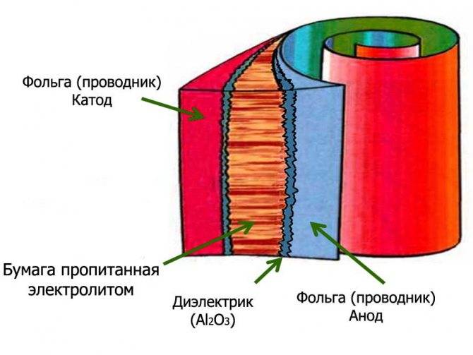
Capacitor device (such a roll is placed in an aluminum case, which in turn is placed in a plastic insulating box)
Today, capacitors are used in almost every electronic circuit. Their failure is most often associated with the expiration of the expiration date. Some electrolytic solutions are characterized by "shrinkage", during which their capacity decreases. This affects the operation of the circuit and the shape of the signal passing through it. It is noteworthy that this is typical even for elements not connected to the circuit. The average service life is 2 years. With this frequency, it is recommended to check all installed elements.
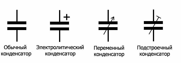
Designation of capacitors on the diagram. Regular, electrolytic, variable and trimmer.
How to test a capacitor with a multimeter
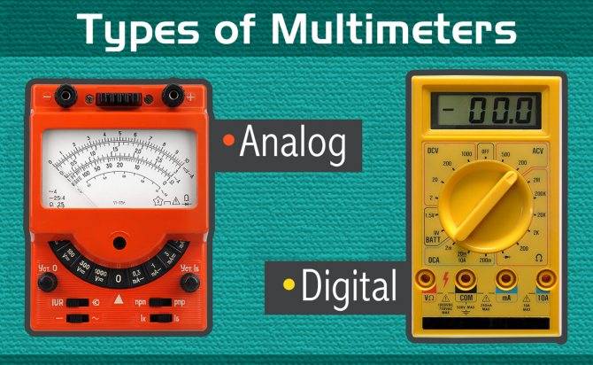
The industry produces several types of test equipment for measuring electrical parameters. Digital ones are more convenient for measurements and give accurate readings. Turnouts are preferred for the visual movement of the arrows.
If the conder looks absolutely intact, it is impossible to check it without instruments. It is better to check with soldering from the circuit. So the indicators are read more accurately. Simple parts rarely fail.Dielectrics are often mechanically damaged. The main characteristic during the test is the passage of only alternating current. Permanent takes place exclusively at the very beginning for a short period of time. The part resistance depends on the existing capacitance.
A prerequisite for checking a polar electrolytic capacitor with a multimeter for operability is a capacity of more than 0.25 microfarads. Step by step verification instructions:
- Discharge the element. For this, its legs are shortened with a metal object. The closure is characterized by the appearance of a spark and sound.
- The multimeter switch is set to the resistance value.
- Touch the probes to the legs of the capacitor, taking into account the polarity. Red to the plus leg, black poke into the minus one. This is only necessary when working with a polar device.
The capacitor starts charging when the probes are connected. The resistance grows to a maximum. If, with the probes, the multimeter squeaks at zero, then a short circuit has occurred. If the value 1 is immediately displayed on the dial, then there is an internal break in the element. Such conders are considered faulty - a short circuit and an open inside the element are unrecoverable.
If the value 1 appears after some time, the element is considered healthy.
Testing a non-polar capacitor is even easier. On the multimeter, we set the measurement to megaohms. After touching the probes, we look at the readings. If they are less than 2 MΩ, the part is faulty. More is correct. There is no need to observe polarity.


Electrolytic
As the name implies, aluminum-cased electrolytic conders are filled with electrolyte between the plates. The dimensions are very different - from millimeters to tens of decimeters.Technical characteristics can exceed those of non-polar ones by 3 orders of magnitude and reach large values - units of mF.

In electrolytic models, an additional defect associated with ESR (equivalent series resistance) appears. This indicator is also abbreviated as ESR. Such capacitors in high-frequency circuits filter the carrier signal from parasitic ones. But EMF suppression is possible, greatly reducing the level and playing the role of a resistor. This leads to overheating of the part structure.
What makes up ESR:
- resistance of plates, leads, connection nodes;
- inhomogeneity of dielectrics, moisture, parasitic impurities;
- electrolyte resistance due to changes in chemical parameters during heating, storage, drying.
In complex circuits, the EPS indicator is especially important, but it is measured only with special devices. Some craftsmen make them on their own and use them in conjunction with conventional multimeters.
Ceramic
First, we inspect the device visually. Be especially careful if used parts are used in the circuit. But even new ceramic materials can be defective. Conders with a breakdown are immediately noticeable - darkened, swollen, burned out, with a cracked body. Such electrical components are unequivocally rejected even without instrumental verification - it is clear that they are inoperative or do not give out the assigned parameters. It is better to attend to the search for the causes of breakdowns. Even new specimens with a crack in the hull are a "time bomb".

Film
Film devices are used in DC circuits, filters, standard resonant circuits. The main malfunctions of devices with low power:
- decrease in performance as a result of drying;
- increase in leakage current parameters;
- increased active losses within the circuit;
- closure on the plates;
- loss of contact;
- conductor break.
It is possible to measure the capacitance of a capacitor in test mode. Arrow models respond by deflecting the arrow with a jump and returning to zero. With a slight deviation, the arrows diagnose current leakage at low capacitance.
The low efficiency with low power level and high leakage current prevents the wide application of these capacitors and does not allow their full potential to be realized. Therefore, the use of this type of conder is impractical.

Control button block: measurement tasks
It is located directly below the LCD screen. The names of the buttons and their functions are collected in a table.
| Button name | Functions |
| Range/Delete | Switching the range of manual measurement / clearing information with deleting data from memory. |
| Store | Stores the displayed data in the instrument's memory with the Sto symbol shown on the display. A long press of the button opens a menu for setting autosave options. |
| Recall | View data from memory. |
| Max/Min | When pressed once, the minimum and maximum values of the measured value are displayed. Pressing and holding starts the PeakHold mode, which takes into account peak current and voltage values. |
| hold | Pressing once - holding (fixing) the data on the screen. Double pressing - returning the measurement mode to the default (Esc). Pressing and holding - switching to the screen backlight mode. |
| Rel | Turns on the mode for measuring relative values. |
| Hz% | Pressing and holding turns on the system settings menu - Setup mode. A single press switches the frequency measurement modes with duty cycle, and also allows you to select the direction in the settings menu. |
| Ok/Select/V.F.C. (Button in blue) | Pressing once - the choice of functions in the settings is turned on (Select mode). Press and hold - Metering mode with low-pass filters. |


