
- Verification methods
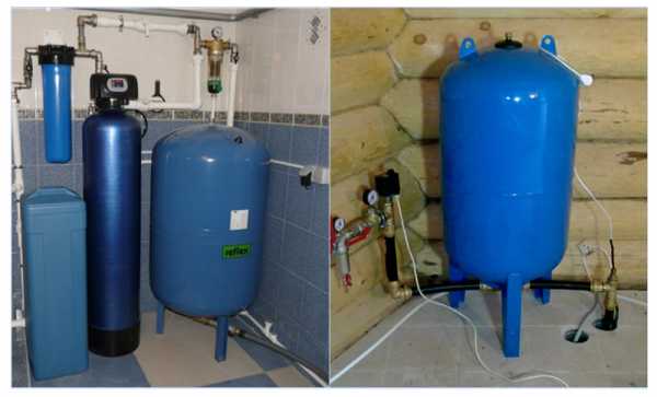
- Installation of a heating accumulator
- The cost of relays and accumulators of some manufacturers
- The principle of operation of the relay
- Pressure value in the accumulator
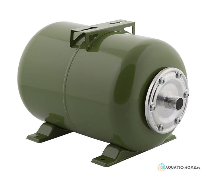
- Types of accumulators
- Advantages and disadvantages of TA
- Carrying out work on connecting and setting up a pressure switch for a hydraulic accumulator
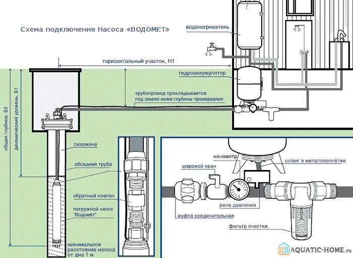
- Standard scheme for connecting a pressure switch to a hydraulic accumulator
- Correct setting of the accumulator pressure switch
- How quickly energy reserves are used up
- How to set up the system for 50 liters?
- Optimal pressure inside the hydraulic tank
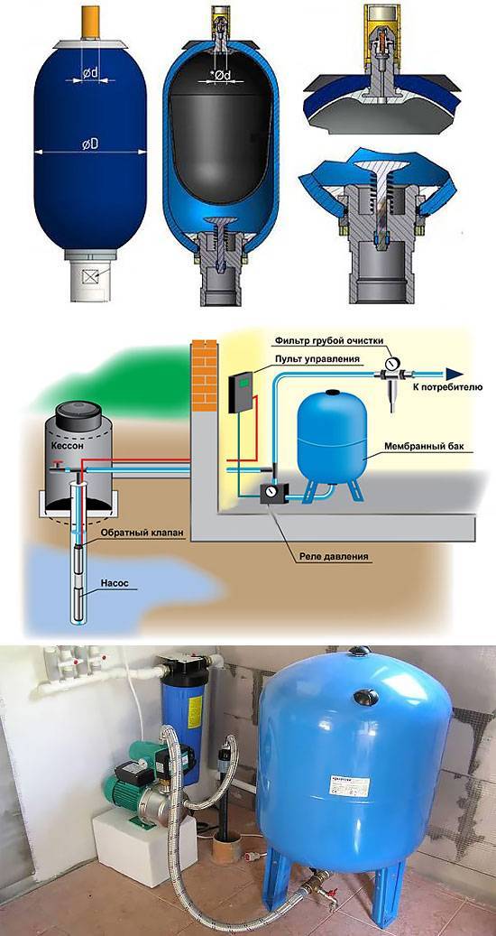
- Do-it-yourself installation steps for a hydroaccumulator for water supply systems
- Choosing a hydraulic tank connection scheme
- Connecting the accumulator to the water supply system
- What pressure should be in the accumulator: we check the system for operability
- Expansion tanks with rubber bulb
- How to properly adjust the pressure in the accumulator
- Working elements of the device and functioning
- How to change a bulb in a pressure water tank
- How to check the membrane in the accumulator for leaks
- The principle of operation of the pressure switch
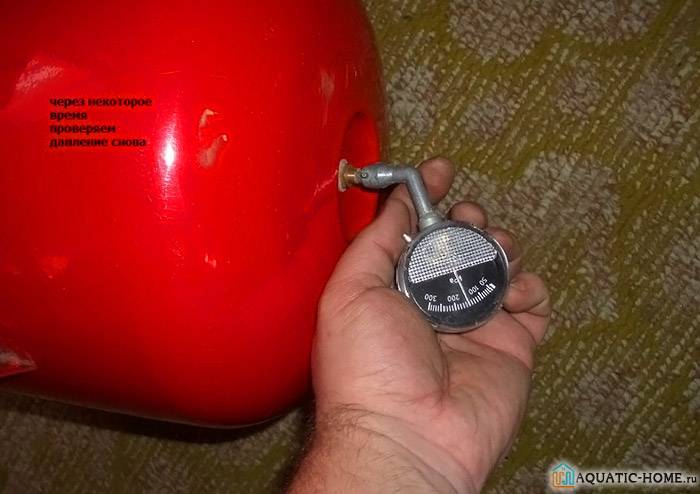
Verification methods
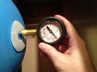
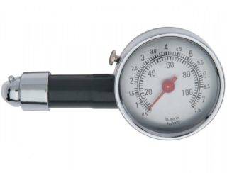 You can use a car pressure gauge to check the pressure.
The air pumped into the tank at the factory is gradually escaping through the rubber membrane and nipple.The rarefaction of the gas cavity leads to excessive stretching of the rubber bulb when it is filled with liquid. Without resistance, the membrane wears out quickly and may burst. Air pressure is measured with a manometer. The best option is an automotive measuring device.
The manufacturer's instructions indicate the number of checks for the device model. The average is 2 times a year. Before starting the parameter measurement procedure, it is necessary to drain all the liquid from the tank. The pump is disconnected from the power supply system. At the time of measurement, the tank must be empty. Control is required before connecting the device to the system. During storage in a warehouse, some air may leak out of the tank. The working pressure is indicated in the product data sheet.
To carry out the check, unscrew the decorative cap that closes the nipple. The node is located in the upper part of the body. A manometer is connected to the spool. The device must have a minimum error. Electronic and automotive devices are recommended. It is better not to use cheap plastic pressure gauges, they have a significant error in indicators. If the level is less than the factory parameters, air is pumped using a compressor. The accumulator is left for a day for control. After the next measurement, corresponding to the norm, the device is installed. Exceeding the optimal pressure is eliminated by bleeding air.
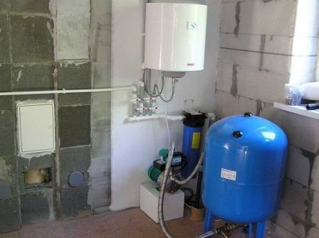
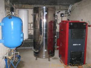
Installation of a heating accumulator
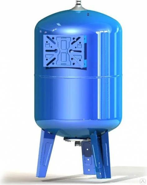
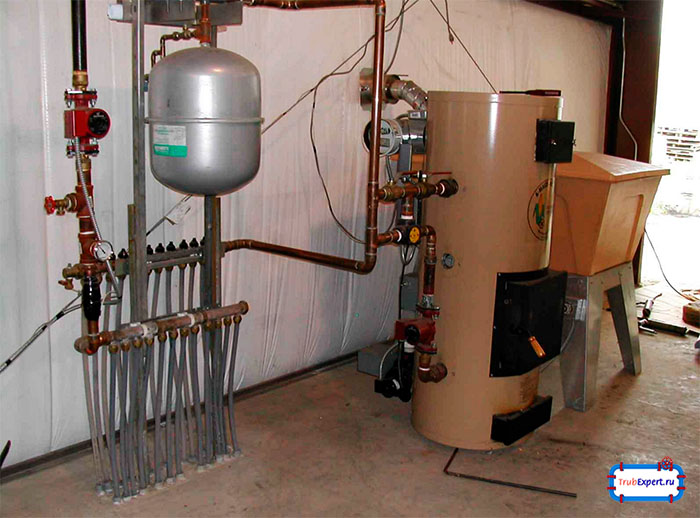
The expansion tank must only be installed in a heated room. If the weight of the accumulator exceeds 30 kilograms, then it is installed on a special stand. The location for the expander should be easily accessible for maintenance.
Heating and water supply systems
The insert is made into the pipes only on the return line. The insert is made between the final radiator, close to the boiler. A non-return valve and a pressure gauge are installed in front of the expansion tank to constantly measure the pressure in the system.
It is best to choose a model with a replaceable membrane, which is replaced in the event of a breakdown without much effort. If possible and desired, the accumulator can be installed without outside help, but if you are not sure or do not want to mess around for a long time, you can hire a specialist. However, in this case, you will not be able to save.
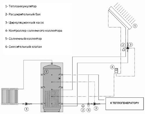
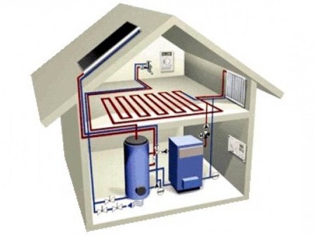
Heat accumulator in solar heating system
The need to improve the heating system of their own home forces owners to constantly search for useful ideas, additional devices that save fuel, evenly distribute heat inside the house, and increase the heat transfer of radiators.
The problem of uniform heat distribution is especially acute in houses with solid fuel boilers. In them, it is impossible to instantly stop the process of fuel combustion and the supply of heat to the pipeline of the system. If you turn off the supply tap, hot water, accumulating at the inlet, can reach the boiling point and damage part of the pipeline. You can distribute the number of kindlings over time. Such solutions are labor-intensive and ineffective. In this case, it is advisable to use a heat accumulator, which will ensure uniform distribution of heat throughout the house and eliminate temperature fluctuations.
In houses where a heat accumulator is built in, heat losses are significantly reduced.
A hydraulic accumulator is a container that accumulates heat produced by a solid fuel boiler, keeping it for a long time. The device works on the principle of a thermos.
The storage tank consists of the following components:
- Container made of steel or stainless steel, large size (rectangular or round);
- Four nozzles inside the tank, spaced apart in height. One is the outlet from the heater to the tank, and the other is the inlet of the heating system, the same at the bottom;
- A safety valve is built into the accumulator at the top;
- Outside, the container is insulated with a thick layer of insulating material.
The buffer tank accumulates the heated coolant inside, maintains heat in the house for up to two days after the heating system is turned off.
When installing a hydraulic accumulator, it is necessary to arrange a piping circuit between it and the boiler, including:
- Circulation pump;
- Thermal mixing valve;
- Expansion tank.
The storage tank must be thermally insulated, otherwise the heat generated will heat the room where the accumulator is located.
The storage tank works like this:
- From a solid fuel boiler, heated water enters the upper pipe;
- The circulation pump, while working, expels cold water from the bottom of the heat accumulator into the solid fuel boiler until the entire tank is filled with hot water;
- The next step is to supply hot water from the battery tank to the heating system. With the help of a circulation pump from the heating system, the cooled water is distilled into the tank, and from the tank into the system.
The cost of relays and accumulators of some manufacturers
Relay models can be purchased relatively inexpensively. Usually the cost of products does not exceed one thousand rubles. However, electronic counterparts may have a higher price, as they allow for more precise tuning. The table shows the models of some manufacturers and their cost.
Presented pressure switch Gileks RDM-5
| Image | Model | Dimensions in mm | Price in rubles |
|---|---|---|---|
| Gilex RDM-5 | 110x110x70 | 900 | |
| Danfoss KP1 | 107x65x105 | 1 570 | |
| Belamos PS-7 | 150x80x150 | 575 | |
| Caliber RD-5 | 103x65x120 | 490 |
As for hydraulic accumulators, their cost can be noticeably higher. It mainly depends on the volume of the structure. A capacious tank can significantly reduce the number of work cycles. However, there is not always enough space for it. The table shows prices for accumulators for water supply of different sizes.


Hydraulic capacity Poplar 24 l
| Manufacturer | Volume in liters | Cost in rubles |
|---|---|---|
| Gilex | 24 | 1 400 |
| 50 | 3 500 | |
| 100 | 6 300 | |
| Poplar | 24 | 1 100 |
| 50 | 2 900 | |
| 100 | 5 100 |
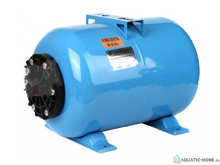
Hydraulic accumulator Gileks, containing 24 liters
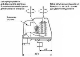
The principle of operation of the relay
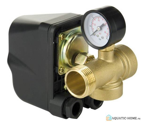
The main element of the pressure switch can be called a group of contacts fixed on a metal base. It is this part that turns the device on and off. There is a large and small spring next to the contacts, they regulate the pressure inside the system and help in solving the issue of how to increase the water pressure in the pumping station. The membrane cover is fixed at the bottom of the metal base, under it you can directly see the membrane and the metal piston. Closes the entire structure with a plastic cap.
To understand how to properly set up a pumping station, you need to know that the pressure switch works according to the following scheme:
- When the tap is opened, water from the storage tank flows to the point of analysis. In the process of emptying the container, the pressure begins to gradually decrease, respectively, the degree of pressure of the membrane on the piston decreases. The contacts close and the pump starts to work.
- During the operation of the pump, the taps at the points of analysis can be open, at this time the water enters the consumer.When the tap is closed, the tank starts filling with water.
- An increase in the water level in the tank leads to an increase in pressure in the system, which begins to put pressure on the membrane. It begins to put pressure on the piston, which helps to open the contacts and stop the pump.
A properly adjusted water pump pressure regulator ensures the normal frequency of switching on and off the pumping station, normal water pressure and equipment life. Incorrectly set parameters cause continuous operation of the pump or its complete stop.
Pressure value in the accumulator
 Optimum pressure in the accumulator provides a constant water pressure and prevents wear of system parts
Inside the hydraulic tank there are two media - air or gas and water filling the rubber membrane. The principle of operation of the device: when the pump is turned on, the liquid enters the expandable container. The gas is compressed, its pressure increases. The air pressure pushes water out of the membrane into the distribution pipes. When the indicator for which the automation is configured is reached, the device turns off. Water consumption comes from the hydroaccumulator reserve. A decrease in fluid volume causes a pressure drop and the pump restarts. The operation of the hydraulic accumulator is controlled by a pressure switch.
The main function of the pressure in the accumulator is to create optimal conditions for the operation of the pumping station. The pressure of air excludes inclusion and deenergizing of the mechanism after each opening of the crane. Installing a storage tank in the water supply system solves other problems:
- Prevention of abrupt changes in pressure in the pipeline (water hammer), causing damage to pipes and mixers.
- Extending the life of pumping equipment, preventing wear of parts and assemblies.
- Creating a reserve of water inside the tank, which is used when there is a power outage.
The choice of tank volume depends on the power and type of pump. Units with a built-in frequency converter are characterized by soft start. For them, a tank with a minimum capacity (24 l) is enough. The lack of mechanisms is high cost; they are rarely used in private households. A common option is budget borehole pumps, which give maximum power at startup. They quickly create a high pressure in the pipes. The membrane tank should compensate for it.
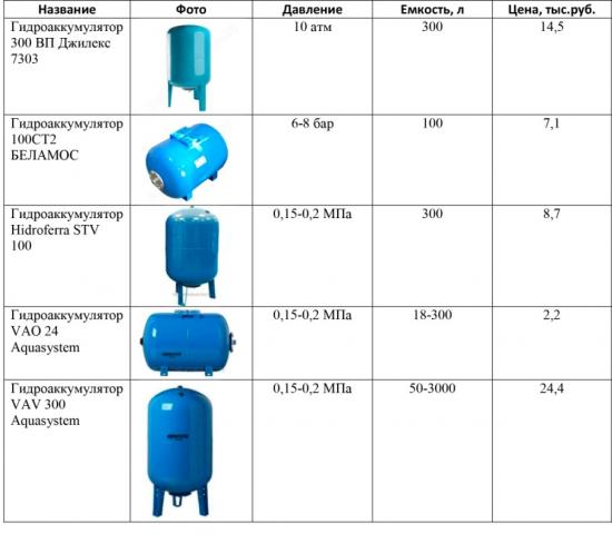
Types of accumulators
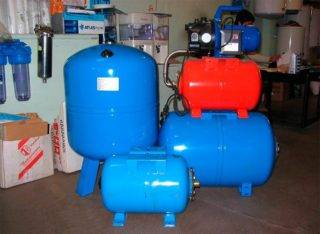 Hydraulic accumulators are used in heating, cold and hot water supply systems.
Tanks differ in size, purpose, execution. The design and function of the tanks remain unchanged.
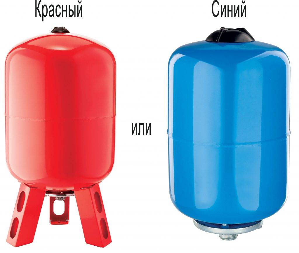
By appointment:
- for hot water (red);
- for cold water (blue).
The difference between storage tanks is in the material from which the membrane is made. In the container intended for drinking (cold) water, rubber safe for human health is used.
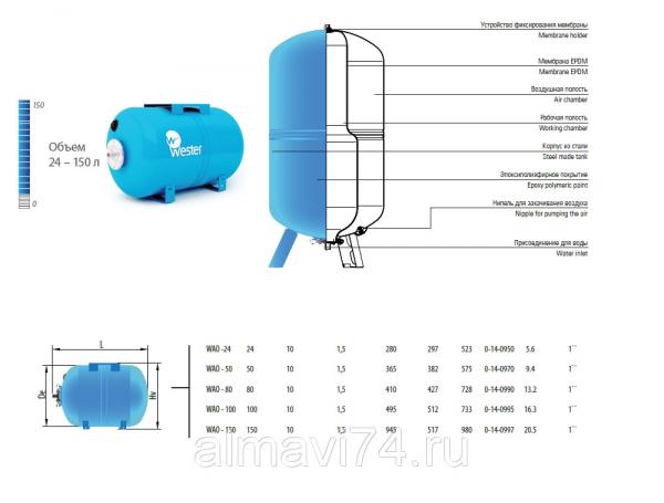
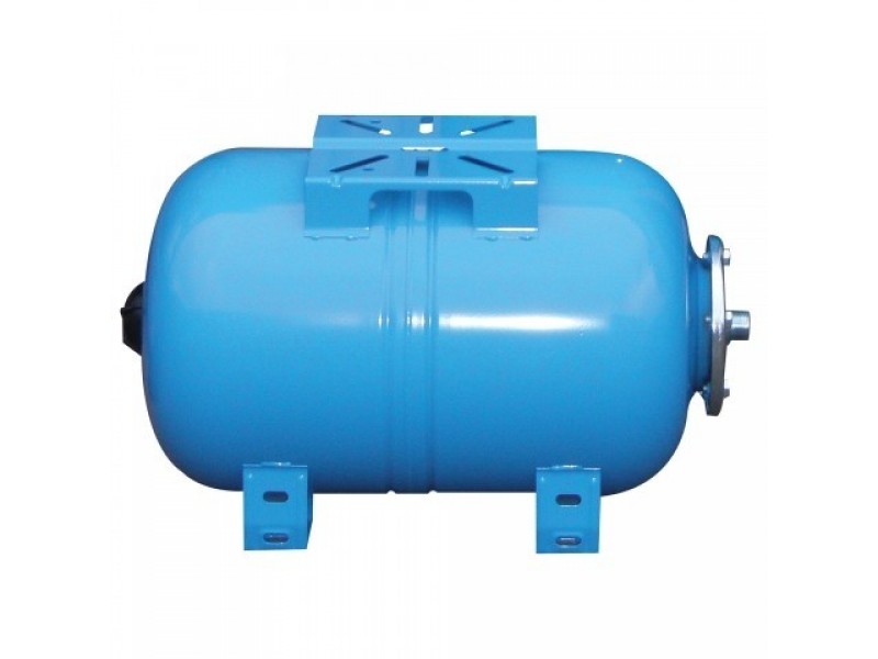
By execution:
- vertical models - used for limited space;
- the horizontal version is used complete with an external pump fixed on the body.
Each type of device is equipped with a special device for bleeding air. A valve is installed in the upper part of the vertical hydraulic tanks. Accumulated air is released through it, preventing the formation of traffic jams in the system. Horizontal tanks have a pipe and ball valve assembly.Drainage is carried out into the sewer. In tanks with a volume of less than 100 liters, valves and drain units are not installed. Air is removed during preventive maintenance.
Advantages and disadvantages of TA
TA dimensions are impressive
Let's start with the benefits of using a hot water and heating storage tank:
- temperature stability in the circuit;
- fuel economy;
- reduction in the number of fuel loadings into the boiler;
- the heater fully realizes its power potential;
- the possibility of saving if an electric boiler acts as a heater;
- simultaneous heating of the heat carrier in the heating circuit and hot water.
There is nothing that does not have its shortcomings. Same with heat sinks.
- take up a lot of space;
- are expensive;
- need a more powerful boiler.
Everyone understands that every business must be done well and efficiently, preferably adhering to all the rules. In practice, unfortunately, this is not always possible. Here you need to count the money, because everything always rests on them. The use of buffer tanks really helps to reduce fuel costs and stabilize the temperature in the circuit. At the same time, initially you will need to buy a boiler twice as powerful, which, of course, is more expensive, and buy the heat accumulator itself, which is also not cheap. You can make purchases gradually, first make a circuit without a storage tank, and then buy it over time if the desire does not disappear. In this case, it will be necessary to slightly correct the layout of the heating pipes.
Interesting on the topic:
- Replacement of heating pipes
- Which heater to choose
- The use of boxes in the heating system
- Features of heating industrial premises
Carrying out work on connecting and setting up a pressure switch for a hydraulic accumulator
Although many people find the process of mounting and adjusting the device difficult to understand, in fact it is not. Each owner of a country house with a well or a well can independently connect and configure a device to provide the building with water.
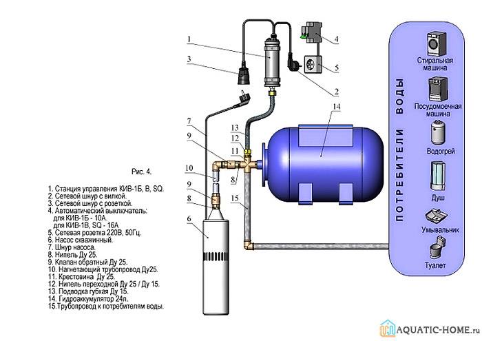
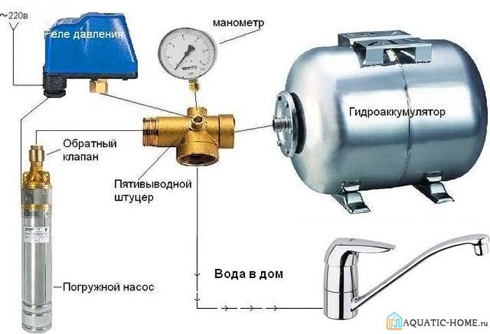
One of the schemes for connecting the accumulator to the system
Standard scheme for connecting a pressure switch to a hydraulic accumulator
The finished product interacts with both the plumbing and electrical systems of the building. When closing and opening contacts, liquid is supplied or blocked. The pressure device is installed permanently, since there is no need to move it from place to place.


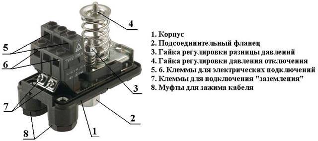
The purpose of the contact groups of the device is indicated
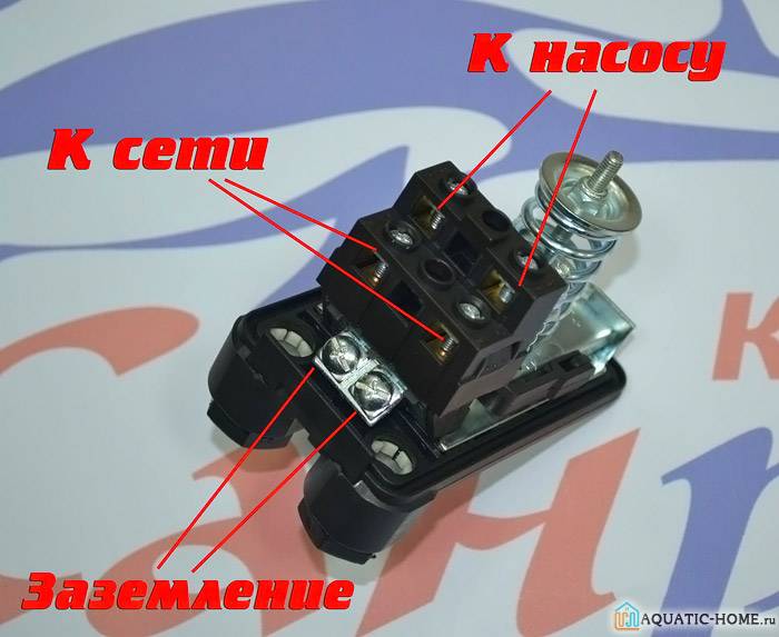
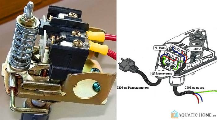
For connection, it is recommended to allocate a separate power line. Directly from the shield should be a cable with a copper core section of 2.5 square meters. mm. It is not recommended to connect wires without grounding, because the combination of water and electricity is fraught with hidden danger.
Visual diagram for independent connection of the relay
Cables should be passed through the holes located on the plastic case, and then connected to the terminal block. It contains terminals for phase and zero, grounding, wires for the pump.
Correct setting of the accumulator pressure switch
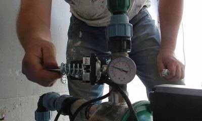
To adjust the device, an accurate pressure gauge is required to determine the pressure without errors. Focusing on its readings, you can make a relatively quick adjustment. By turning the nuts located on the springs, you can reduce or increase the pressure. During setup, you must follow a certain sequence of actions.
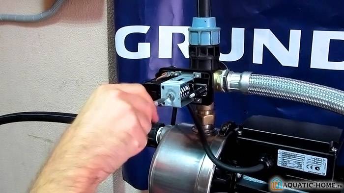
Work is underway to set up the device
So, the adjustment of the pressure switch for the accumulator is carried out as follows.
- The system turns on, after which, using a pressure gauge, the indicators are monitored at which the device is turned on and off;
- First, the lower level spring, which is large, is adjusted. For adjustment, a regular wrench is used.
- The set threshold is being tested. If necessary, the previous paragraph is repeated.
- Next, the nut is turned for the spring, which allows you to set the upper pressure level. It has a smaller size.
- The operation of the system is fully tested. If for some reason the results are not satisfactory, then a reconfiguration is performed.
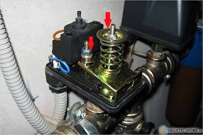
The adjusting nuts of the device are shown
How quickly energy reserves are used up
The accumulative tank for the heating system, included in the circuit, heats the premises when the boiler is turned off, it is not necessary to heat the boiler constantly, while saving fuel up to 30 - 50%.
The backup heat consumption time depends on the following factors.
- Capacity tank sizes.
- Temperatures of the air space inside and outside the room.
- Heat loss.
- "Smart" automation.
- Consumption expense.
Heating with the boiler turned off lasts several hours, or two to three days.
Connection heat accumulator for solid fuel boiler does not allow thermal energy to “fly away into the pipe”. Heat accumulates inside the tank. With automation equipment, the heat supply is economically spent on heating radiators, underfloor heating, and water supply.
If there is a preferential night tariff for electricity, the battery is charged at night.
In order to make a boiler room in the house on your own, you need to think through a lot of details.
1000 l. thermal energy is enough for 11 - 12 daytime hours for a room of 150 square meters. m. This is an effective economical backup heat supply with a difference in tariffs.
How to set up the system for 50 liters?
 After the calculations, it is necessary to measure the air pressure indicator inside the station, the value of which should not exceed 1.5 atm.
It is this indicator that will provide a good pressure of water. The larger the parameter, the less water can flow.
For measurement, you can use a pressure gauge for a car, which helps to calculate the indicator with the least inaccuracy.
After determining the air pressure, it is necessary:
- Start the pump to establish pressure in the system.
- Determine at what point on the pressure gauge the shutdown occurs.
- Set the switch to disable the mechanism.
- Turn on the tap so that the accumulator gets rid of moisture, and fix the indicator.
- Fit the small spring under the formed thresholds.
| Index | Action | Result |
| 3.2-3,3 | Rotation of the screw on a small spring until the motor is completely turned off. | Decrease in indicator |
| Less than 2 | Add pressure | Increase in indicator |
The recommended value is 2 atmospheres.
By adhering to these recommendations, acceptable indicators of the water supply system can be established.
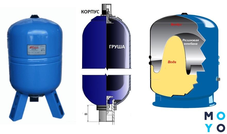
Optimal pressure inside the hydraulic tank
Any accumulator inside has a rubber membrane that divides the space into two chambers. One contains water and the other contains compressed air. Thanks to this structure, it is possible to create the necessary pressure when filling and emptying the rubber container.


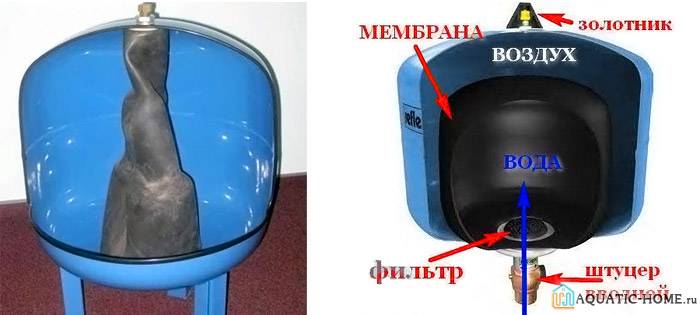
The device of the hydraulic accumulator is clearly shown
To extend the life of the device, you need to know what pressure should be in the accumulator. It largely depends on the indicators set to turn on the pump. The pressure inside the tank should be about 10 percent less.
Tank pressure check
For example, if the switch-on is set to 2.5 bar and the switch-off is set to 3.5 bar, then the air pressure inside the tank should be set to 2.3 bar. Ready-made pumping stations usually do not require additional adjustment.
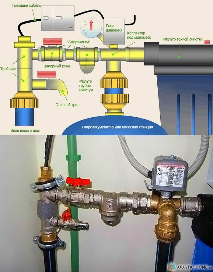
Do-it-yourself installation steps for a hydroaccumulator for water supply systems
Work on the installation of the purchased accumulator is carried out in several stages. The first thing to do is check the pressure in the air chamber. This is done simply, using a car pump or compressor equipped with a pressure gauge. The pressure is made slightly greater than the rate at which the pump turns on. The upper level is set from the relay and is set one atmosphere above the primary level.
Next, you should decide on the installation scheme.

Choosing a hydraulic tank connection scheme
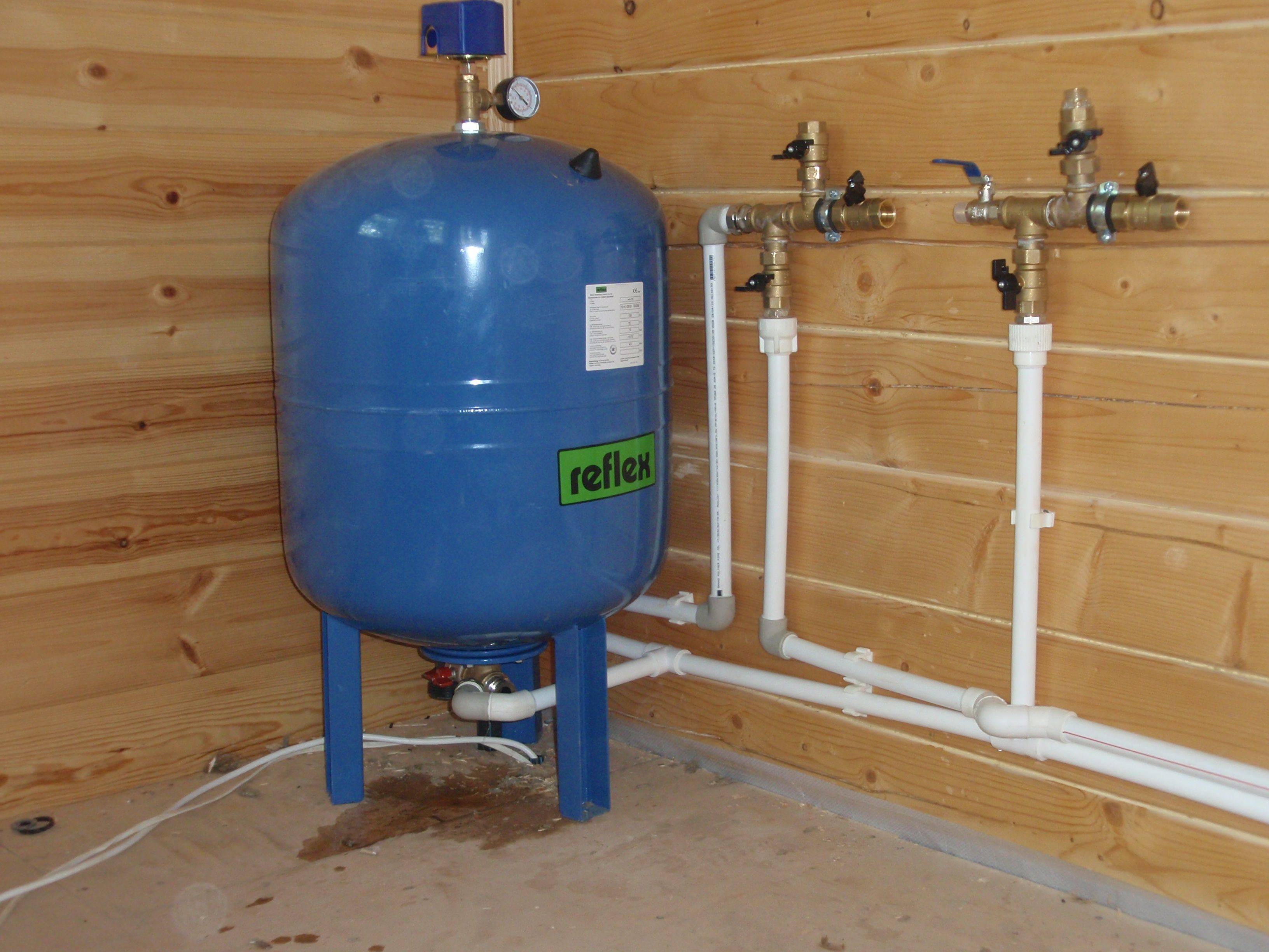
The most convenient is the connection diagram of a hydraulic accumulator with a five-pin collector. Installation is carried out according to the scheme, which is in the technical documentation. A collector with five outlets is screwed to the fitting of the accumulator. The remaining 4 outputs from the collector are occupied by a pipe from the pump, water supply to the dwelling, a control relay and a pressure gauge. If it is not planned to install a measuring device, then the fifth output is muted.
Connecting the accumulator to the water supply system
After assembling all the nodes, the pump (if the system is equipped with a submersible pump) or the hose (if the pump is surface) is first lowered into the well or well. The pump is powered. That, in fact, is all.

Important! All connections are made with winding FUM tape or flax. It should be understood that the pressure in the system will be quite high. However, you should not be too zealous either, everything is good in moderation.
Otherwise, there is a risk of breaking the nuts on the fittings.
However, you should not be too zealous either, everything is good in moderation. Otherwise, there is a risk of breaking the nuts on the fittings.
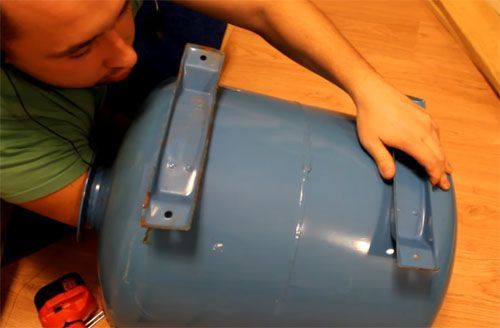
Having dealt with the installation, you can move on to the issue of replacing the membrane, which often fails in models with a vertical arrangement. Here we will make a step-by-step instruction with photo examples.
| Photo example | Action to take |
|---|---|
 | First, we unscrew the bolts of the flange of the dismantled hydraulic tank. They are wrapped "in the body" or tightened with nuts - depending on the model. |
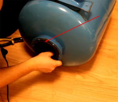
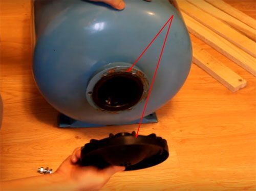 | When the bolts are out, the flange can be easily removed. Let's put it aside for now - to pull out the failed pear, you need to unscrew one more nut. |
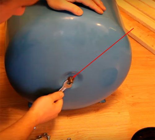 | Expand the container. At the back is a purge nipple. The nut also needs to be removed. There may be two of them, one of which acts as a locknut. This is done with a key of 12. |
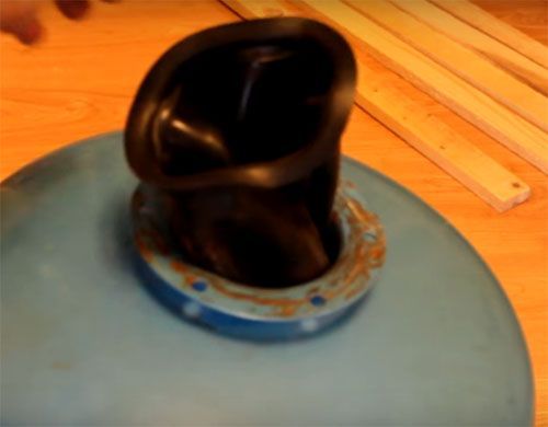 | Now, with a little effort, the pear is pulled out through the large hole on the side of the flange. |
 | We lay out a new pear, we expel air from it. This is necessary to make it more convenient to install it in the tank. |
 | Having folded four times in length, we put it into the container completely, including the part that was outside during dismantling. This is done so that it is possible to get the nipple into the hole intended for it. |
 | The next stage is not for people with a full physique. Experienced craftsmen say that in order to install the nipple for the accumulator in place, sometimes you have to call your wife for help - they say, her hand is thinner. |
 | Once in the hole, it is imperative to make a nut so that during further assembly it does not go back. In this case, you will have to start all over again. |
 | We straighten the pear seat and tighten the nuts on the nipple. The matter remains small ... |
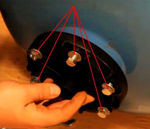 | ... - put the flange in place and tighten the bolts. When tightening, do not be zealous over one screw. Having pulled everything up a little, we begin broach through the system of opposite units. This means with six bolts the order is as follows - 1,4,2,5,3,6. This method is used in tire shops when pulling wheels. |
Now it is worthwhile to deal with the necessary pressure in more detail.
What pressure should be in the accumulator: we check the system for operability
The factory settings of the hydraulic tanks imply a set pressure of 1.5 atm. It does not depend on the volume of the tank. In other words, the air pressure in a 50-liter accumulator will be the same as in a 150-liter tank. If the factory settings are not suitable, you can reset the indicators to values \u200b\u200bthat are convenient for the home master.
Very important! Do not overestimate the pressure in the accumulators (24 liters, 50 or 100 - it doesn’t matter). This is fraught with failure of faucets, household appliances, pump. 1.5 atm., installed from the factory, not taken from the ceiling
This parameter is calculated on the basis of numerous tests and experiments.
1.5 atm., installed from the factory, are not taken from the ceiling. This parameter is calculated on the basis of numerous tests and experiments.

Expansion tanks with rubber bulb
Replacing a pear in a hydraulic accumulator for 20, 24, 50, 80 and 100 liters is done in the same way.
Hydraulic accumulators are energy storage devices. Like batteries in electrical systems, they store and discharge energy as a liquid under pressure.


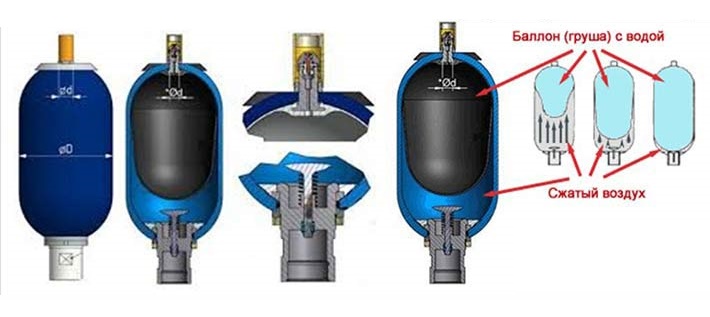


The accumulator itself is a pressure vessel that contains hydraulic fluid and a compressible gas, usually nitrogen. The body or shell is made of steel and aluminum, titanium and fiber-reinforced composite materials. A movable rubber bladder inside the body separates the water from the gas.

In these hydropneumatic units, fluids are slightly compressed under pressure. But gases are compressed into smaller volumes under high pressure, and engineers use this property in the design of expansion tanks for plumbing. Potential energy is stored in the compressed gas and released on demand to force fluid out of the battery and into the home's water supply.
The hydraulic pump pressurizes the system and forces fluid into the accumulator. The bulb for the expansion tank inflates and compresses the volume of gas, and the battery stores energy.
Water injection stops when system pressure and gas are balanced. When water flows out of a faucet or shower, the pressure in the hydraulic system drops and the accumulator releases the pressurized accumulated fluid into the circuit. And the charging cycle starts again.
Drillers recommend rubber-diaphragm accumulators as the best expansion tanks. They are made in standard sizes (24, 50, 80, 100 liters). Depending on the design, you can replace the pear in the accumulator in case of failure or damage to the tank yourself.

How to properly adjust the pressure in the accumulator
 Setting the pressure switch
Correct operation of the pumping station requires the correct setting of three main parameters:
- The pressure at which the pump turns on.
- The shutdown level of a functioning unit.
- Air pressure in the membrane tank.
The first two parameters are controlled by the pressure switch. The device is installed on the inlet fitting of the accumulator. Its adjustment takes place empirically, to reduce the error of the action, it is performed several times. The relay design includes two vertical springs. They are planted on a metal axis and secured with nuts. The parts differ in size: a large spring controls the activation of the pump, a small one is required to set the difference between upper and lower pressure. The springs are connected to a membrane that closes and opens electrical contacts.
Adjustment is made by turning the nut with a wrench. Clockwise rotation compresses the spring and increases the threshold for turning on the pump. Turning counterclockwise weakens the part and reduces the actuation parameter. The adjustment procedure takes place according to a certain scheme:
- The air pressure in the tank is checked, if necessary, it is pumped up by the compressor.
- The large spring nut turns in the right direction.
- The water tap opens. The pressure drops, at a certain moment the pump turns on. The pressure value is marked on the manometer. If necessary, the procedure is repeated
- The difference in performance and the shutdown limit is regulated by a small spring. It is sensitive to the setting, so the rotation is carried out by half or a quarter of a turn.
- The indicator is determined with the taps closed and the pump turned on. The pressure gauge will show the value at which the contacts will open and the unit will turn off.If it is from 3 atmospheres and above, the spring should be loosened.
- Drain the water and restart the unit. The procedure is repeated until the required parameters are obtained.
The factory settings of the relay are taken as a basis. They are indicated in the device passport. The average pump start indicator is 1.4-1.8 bar, shutdowns are 2.5-3 bar.
Working elements of the device and functioning
From the point of view of design features, the relay is a small unit equipped with special springs. The first of them defines the limit of maximum pressure, and the second defines the minimum. Adjustment is made by means of the auxiliary nuts placed in the case.
Familiarization with the internal structure of the device
The working springs are connected to the membrane, which reacts to pressure surges in one way or another. Exceeding the maximum values leads to compression of the metal spiral, and a decrease leads to stretching. Thanks to such a device, in the contact group, contacts are closed and opened at a certain moment.
The location of the device in the general scheme
The principle of operation of the pressure switch for the accumulator is as follows. Water enters the membrane tank until it is completely filled, which leads to an increase in pressure. When the maximum allowable level is reached, the pump stops pumping liquid.
As water flows, the pressure in the system drops. When the lower level is overcome, the equipment will turn on again. The cycles of turning on and off are repeated over and over again until the elements of the system are in working condition.
Connection diagram with a drain valve in the system
Typically, a relay consists of the following elements:
- plastic cases;
- rubber membrane;
- brass piston;
- membrane cover;
- threaded studs;
- metal plate;
- couplings for cable fastening;
- blocks for terminals;
- articulated platform;
- adjusting springs;
- contact node.
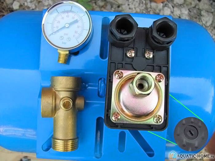
A manometer can be used to visually determine the pressure
How to change a bulb in a pressure water tank
A pressure accumulator with an internal rubber membrane is a way to supply water to a plumbing system. When the faucet is open, the pressure in the tank pushes the water out of the bag and the pump is idle. The pump only works to fill the tank to the set pressure.
Frequent turning on of the pump or problems with low water pressure lead to malfunctions and replacement of the rubber bulb in the accumulator.
Disconnect water and electricity from the pump.
Open the valve closest to the accumulator to drain the water and relieve pressure in the system.
Disconnect the tank from the plumbing system and drain any remaining water.
Remove the nuts holding the cover flange in place. Remove cover flange.
Remove damaged accumulator rubber bag


Pry off the rubber bulb rim seal from the edge of the accumulator and pull it out through the hole.
Installing a diaphragm in a hydraulic accumulator requires caution. Install the new membrane by rolling and sliding through the hole in the reservoir.
Firmly press the edges of the pear to the reservoir opening.
Replace the cover flange, making sure that it does not press against the rim of the accumulator rubber bulb, damaging it.
Tighten the nuts to hold the flange in place
Be careful not to overtighten them and damage the flange.
Remove the air valve cap and charge the tank to the correct pressure. Check for leaks around the flange. Tighten the air valve cap.
Install the tank in place in the plumbing system. Turn on the water supply, and reconnect the power to the pump. Monitor the new installation for any leaks.
Video on the topic of how to change a pear in a hydraulic accumulator with a Gilex nipple, 6.47 minutes long:
How to check the membrane in the accumulator for leaks
The service life of the accumulator membrane is 6-8 years.
Signs of leakage:
- The water drained from the tank goes with air. The principle of operation of the accumulator does not allow mixing of liquid and gas. If this happens, then the pear in the accumulator needs to be replaced.
- A mixture of air and water comes out of the nipple. When you pull out the membrane, check if there is water inside the tank. If the tank is dry, then the pear is intact and there is a problem with tightness inside the nipple itself.
- The water from the faucet changes temperature dramatically.
- Cyclic switching on and off of the pump.
- Condensation on the tank in a warm room indicates that the inner walls, instead of air, are in contact with cold water from the well.
The optimal mounting position for any accumulator is vertical, with the hydraulic opening down.
When solid contaminants enter the water supply, horizontal installation contributes to uneven or accelerated membrane wear.
There is uneven wear of the pear, as it rubs the top of the body, floating in the liquid. The degree of damage depends on fluid cleanliness, cycle speed and compression ratio (defined as the maximum pressure in the system / to the minimum).
The principle of operation of the pressure switch
An autonomous water supply system in a private house consists of water pipes, a pump, and controls and cleaning elements. The hydraulic accumulator in it plays the role of a water pressure control device. First, the latter is stored in the battery, and then, as necessary, it is consumed when the taps are opened.
This configuration of the water supply system allows you to reduce the operating time of the pumping station, as well as the number of its “on / off” cycles.
The pressure switch here performs the function of controlling the pump. It monitors the level of filling of the accumulator with water, so that when this tank is empty, it will turn on the pumping of liquid from the water intake in time.
The main elements of the relay are two springs for setting pressure parameters, a membrane responsive to water pressure with a metal insert and a 220 V contact group
If the water pressure in the system is within the parameters set on the relay, then the pump does not work. If the pressure drops below the minimum setting Pstart (Pmin, Ron), then an electric current is supplied to the pumping station to make it work.
Further, when the accumulator is filled to Рstop (Pmax, Рoff), the pump is de-energized and switched off.
Step by step, the relay in question works as follows:
- There is no water in the accumulator. The pressure is below Pstart - set by a large spring, the membrane in the relay is displaced and closes the electrical contacts.
- Water begins to flow into the system. When Rstop is reached, the difference between the upper and lower pressures is set by a small spring, the membrane moves and opens the contacts. As a result, the pump stops working.
- Someone in the house opens a faucet or turns on a washing machine - there is a decrease in pressure in the water supply.Further, at some point, the water in the system becomes too small, the pressure again reaches Rpusk. And the pump turns on again.
Without a pressure switch, all these manipulations with turning the pumping station on / off would have to be done manually.
The data sheet for the pressure switch for accumulators indicates the factory settings to which the control springs are initially set - almost always these settings have to be changed to more suitable ones
When choosing the pressure switch in question, first of all, you should look at:
- the maximum temperature of the working environment - for hot water and heating, their own sensors, for cold water, their own;
- pressure adjustment range - the possible settings of Pstop and Rpusk must correspond to your particular system;
- maximum operating current - the pump power should not be higher than this parameter.
The setting of the pressure switch under consideration is made on the basis of calculations, taking into account the capacity of the accumulator, the average one-time water consumption by consumers in the house and the maximum possible pressure in the system.
The larger the battery and the greater the difference between Rstop and Rstart, the less often the pump will turn on.


