- Wiring diagrams for switches and lamps of various types
- One-button switch - a circuit for switching on one or more lamps at the same time
- Connecting a chandelier with a fan
- Proximity switches
- Connection of a switch with light bulbs connected in parallel
- How to connect a switch?
- Installation of pre-installation elements of the single-key switch circuit
- Connection diagram of a single-gang switch
- Connecting the switch to the network
- Scheme of connecting a pass-through switch from 2 places
- Installation procedure for 2-point walk-through switches: wiring diagram
- Power calculation for RCD
- Calculating power for a simple single-level circuit
- We calculate the power for a single-level circuit with several protection devices
- We calculate the power for a two-level circuit
- RCD power table
- Switch installation
Wiring diagrams for switches and lamps of various types
The choice of connection scheme depends on the number of lighting fixtures and points to control their operation. Below we consider the most common of them.
One-button switch - a circuit for switching on one or more lamps at the same time
The most commonly used lighting connection option is a single-gang switch.With it, you can turn on and off both one lighting device, and several at the same time. Such a switch is mounted in a standard socket box, in case of flush-mounted electrical wiring. Or it can be overhead, when laying the cable in an open way. Installation of electrical wiring and connection of lamps and switches occurs in the following sequence:
- A supply cable is being laid from the electrical panel to the junction box above the location of the future switch;
- A place is being prepared for installing the switch and from it along the wall, strictly vertically, a two-wire wire is connected to the junction box;
- From the junction box to the lighting fixtures (regardless of the number of lamps), an electric cable is supplied in a three-core (if it is necessary to ground the device) or two-core version (without grounding);
- The switch is installed according to the diagram indicated on the device;
- In the junction box, power lines, lamps and switches are connected according to the diagram for a single-gang switch.
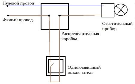
Wiring diagram such a switch for one device is as follows.
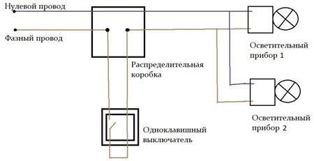
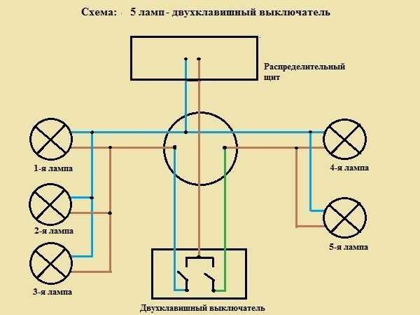
For several lighting fixtures that will turn on at the same time, the circuit will change slightly.
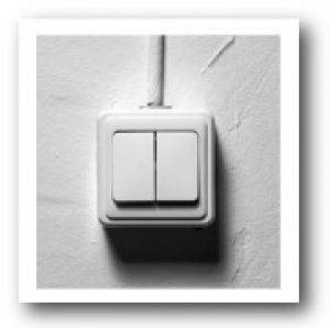
The connection of two-gang or three-gang switches is carried out similarly to the one-gang version. The difference lies in the number of cores that are connected to the switch and the wiring diagrams in the junction box.
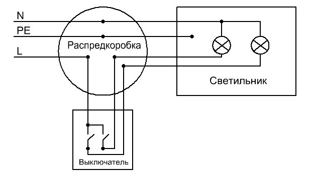
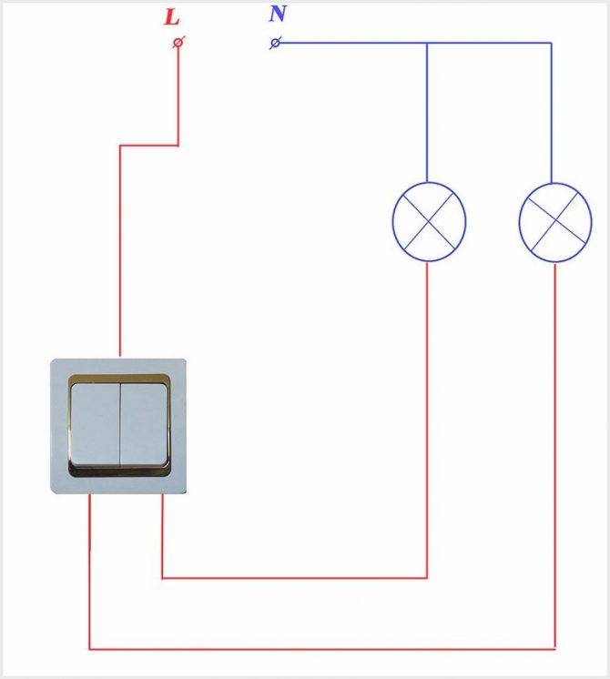
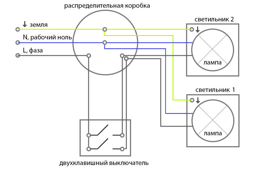
A two-gang switch can be used to control two separate lamps, as well as the operation of one chandelier with several lamps.To do this, one supply phase wire is connected to the switch and two outgoing lines to the junction box. The phase and neutral conductors are brought to the junction box from the electrical panel, and from the lighting devices, zero and phase from each device.
Connecting a two-gang switch and two lamps (or one chandelier with two modes of operation) is as follows.
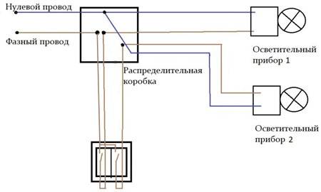
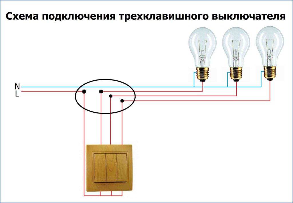
The installation of a circuit with three lamps and a three-gang switch is also carried out, only one more outgoing wire from the switch and one more lighting device are added.
Connecting a chandelier with a fan
Connecting a device such as a chandelier with a fan can be done in two ways: with the fan and lighting turned on at the same time, as well as with the possibility of separately turning on each mode.
The first option involves the installation of a system with a single-gang switch, in the same way as if two simultaneously turned on lamps were mounted.
The second option requires laying three cores to a two-gang switch (one key turns on the light, the second turns on the fan) and three cores to a chandelier with a fan, by analogy with the circuit for two independent lighting fixtures.
The choice of scheme depends on the desire of the user, as well as the type and number of cable cores laid to the switch and the suspension point of the chandelier with a fan.
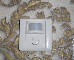
Proximity switches
This type of control device is used to automatically turn on the lighting. Proximity switches include various control devices, the design of which includes sensors: light sensor, motion sensor or timer.


The light sensor is used to turn on the light when insufficient light is detected. For example, this way you can turn on street lighting at dusk.
The motion sensor allows you to turn on lighting devices when motion is detected, for example, when a person enters a room. They can have different versions: infrared, ultrasonic, radio wave or photoelectric. Such devices allow you to save electrical energy, are easy to install and convenient to use.
The timer can be built into a separate control device, or into the lighting fixture itself. It turns on or off the lamp at a user-defined time.
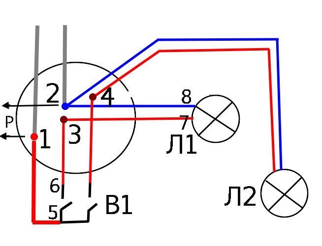
Connection of a switch with light bulbs connected in parallel
This connection of the light bulb is different in that with it, when the button is pressed, another light source is turned on. A definite plus is that if one of the lamps burns out, the other remains operational. The serial scheme of connecting light bulbs to the switch does not allow you to determine by visual inspection which one needs to be replaced. Therefore, this option with parallel connection is considered the best. It makes sense to use multi-colored wires. Choose red if you want to extend the "phase".
To safely connect a light bulb, use certified sockets with special connectors equipped with screw terminals.The essence of the scheme is to connect the power core to the open contact of the switch, which is then extended to two lamps, and after that (already, say, white) the cable returns to the junction box through the "zero" connection of the switch. Thus, in the "OFF" position, the phase is interrupted.

How to connect a switch?
After you have made all the wire connections in the switch, you will need to install it. Almost anyone can install a switch, and now we'll talk about it. After you have summed up the wires, they must be securely fastened.

Now you can start fixing it in the junction box. In the junction box, it will be attached using special clips. They are located on the sides of this product. First, insert the switch into the socket, and then clamp its contacts with a screwdriver. After tightening the bolts, the switch will be securely held in the wall.

After the core of the switch is securely fixed in the gate, you can proceed to install the decorative frame. After the decorative frame is installed, you can start checking the device for device performance. Here is a detailed installation guide for this device. As you can see, almost anyone can connect a switch.
Installation of pre-installation elements of the single-key switch circuit
Any scheme begins with a junction box. It is in it that all the necessary wires will soon be collected, the cores of which will be connected to each other in a certain sequence, creating a single-gang switch circuit.
In this example, a hidden wiring method is shown, in a compact form, you lead what is usually under the plaster.For hidden and open wiring, the circuit for connecting the switch is the same.
We mount the socket box, it is the basis for mounting the mechanism of the socket or switch.

In more detail, the installation of this element of the circuit is presented on our website in the following instructions, the installation of underlays for concrete and drywall.
Now, let's add a circuit breaker, it performs the function of protecting the electrical circuit from overload and short circuit currents, it is usually installed in the power panel.
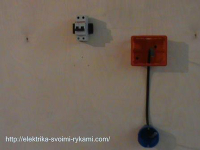
For a complete picture, we lack the last element of the circuit - a lamp, we will install it a little later, and now we are moving on to the next step.
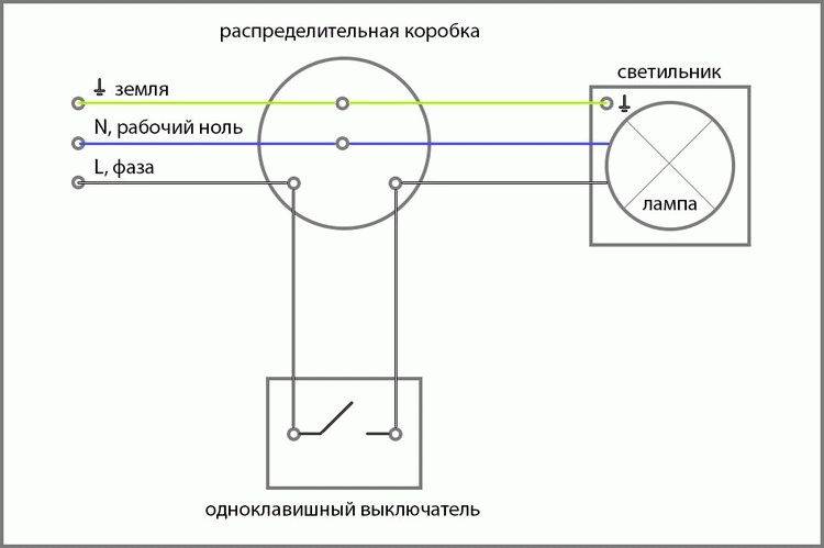
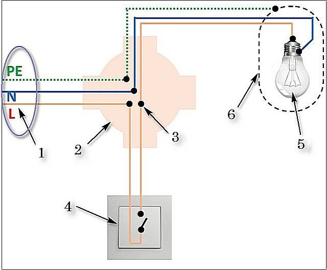
Connection diagram of a single-gang switch
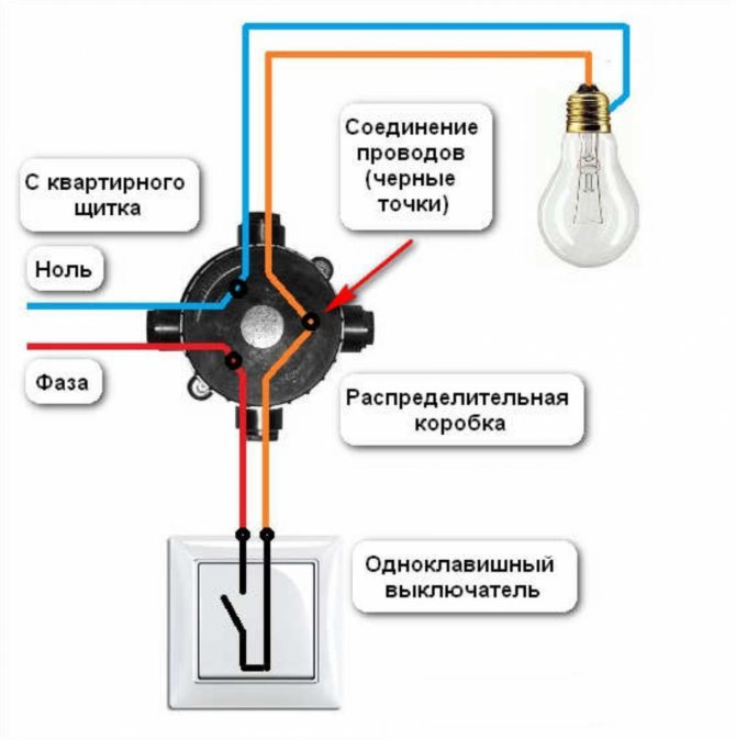
The main rule that must be observed when installing switching devices is the need to install them on a phase conductor. In other words, when a light bulb, lamp or other consumer is turned off using such a device, a phase disappears at its input. This gives a guarantee of protection against accidental electric shock in the event of a violation of the insulation of the electrical wiring or when touching open live parts.


The light switch is installed according to the diagram shown in the figure.
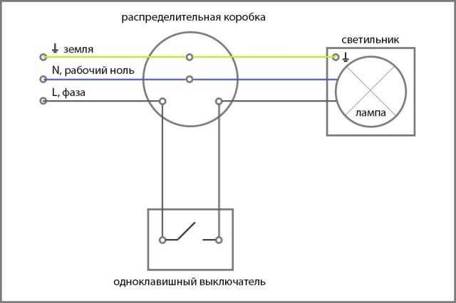
As can be seen from the diagram, the correct connection of the light switch does not cause any difficulties. The picture also shows the ground wire going through the junction box to the luminaire. In the electrical wiring of old houses, such a conductor may be absent.
For the correct connection of the wires in the junction box, it is better to check once again that the conductor going through the switch to the lamp is exactly phase.The easiest way to do this is to use an ordinary indicator screwdriver.
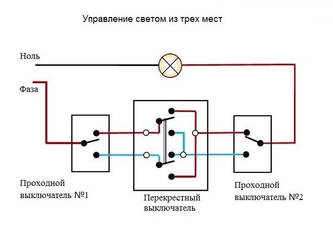
Somewhat more complex is the single-gang switch feedthrough, which is used to ensure ease of use of lighting, for example, in long corridors or for connecting outdoor lamps. Using this scheme, it is possible to turn on and off such lamps using two switches located in different places.

As can be seen from the diagram, it provides two different paths for the passage of current through two switches installed in the circuit. The luminaires are powered only if the contacts of the switches close the conductors of the same branch. This can be done by changing the key position of any of them.
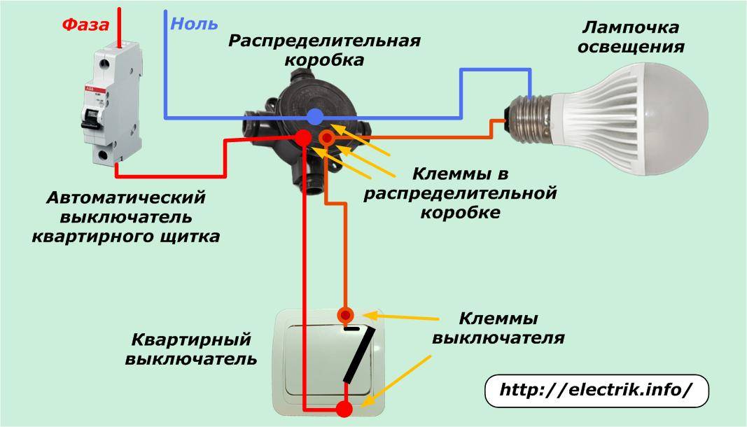
Connecting the switch to the network

When to Connect light bulb through switch, the scheme is not just a recommendation. This is a guide to action. It cannot be changed. The place of installation of the latter is the break of the "Zero" cable. And the step by step algorithm is as follows:
- The core before laying in the contact connector is stripped of insulation by about 1 cm.
- The bare part is inserted into the hole until it stops, loosening the bolts in advance.
- The screws are tightened until a secure connection is achieved. The wire is immobilized.
- The same actions are performed with the second cable. The sequence of events is identical.
- The interior of the switch is placed in the cup holder, the spacer mechanism is actuated.

When using pliers and screwdrivers, do not use excessive force. Metal is soft, plastic is brittle.Otherwise, you can damage the nodes, which will lead to the need to spend money on purchasing a new device.
However, it is impossible to clamp the contacts too weakly.
It is important that the cord does not move along the axis of the contact hole, does not fall out, does not break, does not twist. Then the switch will last a long time, and will not require repair and replacement.
HelpfulUseless


Scheme of connecting a pass-through switch from 2 places
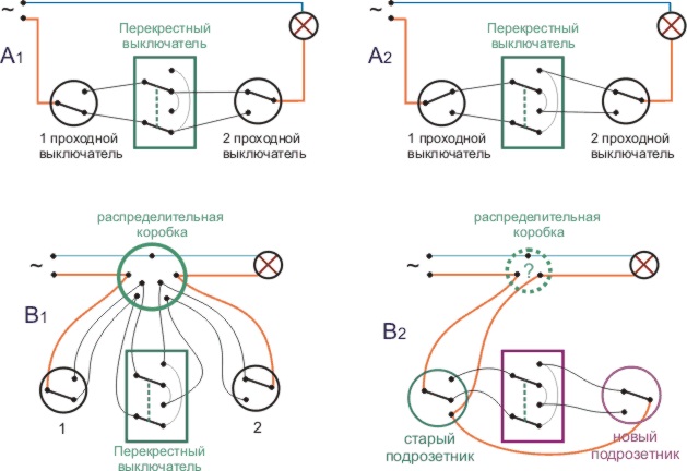
The circuit of the pass-through switch from two places is carried out using two pass-through single-key devices that work only in pairs. Each of them has one contact at the entry point, and a pair at the exit point.
Before connecting the feed-through switch, the connection diagram clearly shows all the steps, you should de-energize the room using the appropriate switch located in the control panel. After that, it is necessary to additionally check the absence of voltage in all the wires of the switch. To do this, use a special screwdriver.
To perform the work you will need: flat, Phillips and indicator screwdrivers, a knife, side cutters, a level, a tape measure and a puncher. To install switches and lay wires in the walls of the room, it is necessary to make the appropriate holes and gates, according to the layout plan of the devices.
Unlike conventional switches, pass-through switches have not two, but three contacts and can switch the “phase” from the first contact to the second or third
Wires must be laid at a distance of at least 15 cm from the ceiling. They can be located not only in a hidden way, but also be stacked in trays or boxes. Such installation makes it possible to quickly perform repairs in case of damage to the cable.The ends of the wires must be brought into the junction boxes, in which all connections are also made using contactors.
Installation procedure for 2-point walk-through switches: wiring diagram
All actions for installing switching devices are carried out on the basis of a connection diagram of 2 places of pass-through switches, which can be found on the Internet. It differs from the installation of conventional switches, since there are three wires here instead of the usual two. In this case, two wires are used as a jumper between two switches located in different places in the room, and the third one is used to supply the phase.
Any type of lamps can be used as a light source in such a scheme - from conventional incandescent lamps to fluorescent, energy-saving and LED
Five wires should be suitable for the junction box: the power supply from the machine, three cables going to the switches, and a connected wire directed to the lighting fixture. When constructing a connection diagram for a single-gang pass-through switch, three-core cables are used. The zero wire and ground are led directly to the light source. The brown wire of the phase, which supplies current, passes through the switches, according to the diagram, and is output to the lighting lamp.
The switches are connected at the break of the phase wire, and zero, having passed the junction box, is directed to the lighting fixture. Passing the phase through the switch will ensure safety during repair and maintenance of the luminaire.
Installing the pass switch consists of the following sequence of actions:
- the ends of the wires are stripped of insulation;
- using the indicator, it is necessary to determine the phase wire;
- using twisting, the phase wire should be connected to one of the wires on the first switch (white or red wires are used here);
- the wires are connected to each other by the zero terminals of the switches;
- connecting a separate wire of the second switch to the lamp;
- in the junction box, the wire from the lamp is connected to the neutral wire;
When installing walk-through switches yourself, you need to take care of safety
Power calculation for RCD
Each individual device has its own threshold current load, at which it will work normally and will not burn out. Naturally, it must be higher than the total current load of all devices connected to the RCD. There are three types of RCD connection schemes, for each of which the calculation of the power of the device is different:
- A simple single-level circuit with one protection device.
- Single-level scheme with several protection devices.
- Two-level trip protection circuit.
Calculating power for a simple single-level circuit
A simple single-level circuit is characterized by the presence of one RCD, which is installed after the counter. Its rated current load must be higher than the total current load of all consumers connected to it. Suppose the apartment has a boiler with a capacity of 1.6 kW, a washing machine for 2.3 kW, several light bulbs with a total of 0.5 kW and other electrical appliances for 2.5 kW. Then the calculation of the current load will be as follows:
(1600+2300+500+2500)/220 = 31.3 A
This means that for this apartment you will need a device with a current load of at least 31.3 A. The nearest RCD in terms of power is 32 A.It will be enough even if all household appliances are turned on at the same time.


One such suitable device is the RCD ERA NO-902-126 VD63, designed for a rated current of 32 A and a leakage current of 30 mA.
We calculate the power for a single-level circuit with several protection devices
Such a branched single-level circuit assumes the presence of an additional bus in the meter device, from which wires depart, forming into separate groups for individual RCDs. Thanks to this, it is possible to install several devices on different groups of consumers or on different phases (with a three-phase network connection). Usually a separate RCD is installed on the washing machine, and the rest of the devices are mounted for consumers, which are formed into groups. Suppose you decide to install an RCD for a washing machine with a power of 2.3 kW, a separate device for a boiler with a power of 1.6 kW and an additional RCD for the rest of the equipment with a total power of 3 kW. Then the calculations will be as follows:
- For a washing machine - 2300/220 = 10.5 A
- For a boiler - 1600/220 = 7.3 A
- For the rest of the equipment - 3000/220 = 13.6 A
Given the calculations for this branched single-level circuit, three devices with a capacity of 8, 13 and 16 A will be required. For the most part, such connection schemes are applicable for apartments, garages, temporary buildings, etc.
By the way, if you don’t want to bother with installing such a circuit, then pay attention to portable RCD adapters that can be quickly switched between sockets. They are designed for one appliance.
We calculate the power for a two-level circuit
The principle of calculating the power of a residual current device in a two-level circuit is the same as in a single-level one, with the only difference being the presence of an additional RCD located at the entrance to the apartment, up to the meter. Its rated current load must correspond to the total current load of all devices in the apartment, including the meter. We note the most common RCD indicators for current load: 4 A, 5 A, 6 A, 8 A, 10 A, 13 A, 16 A, 20 A, 25 A, 32 A, 40 A, 50 A, etc.
The RCD at the input will protect the apartment from a fire, and the devices installed on individual groups of consumers will protect a person from electric shock. This scheme is the most convenient in terms of repairing electrical wiring, as it allows you to turn off a separate section without turning off the whole house. Also, if you need to repair cable systems at the enterprise, you will not have to turn off all office premises, which means there will be no massive downtime. The only drawback is the considerable cost of installing an RCD (depending on the number of devices).
If you need to choose an RCD for a group of machines for a single-phase network, then we can advise the ERA NO-902-129 VD63 model with a rated current load of 63 A - this is enough for all electrical appliances in the house.
RCD power table
If you are thinking about how to easily and quickly select an RCD by power, the table below will help you with this:
| Total load power kW | 2.2 | 3.5 | 5.5 | 7 | 8.8 | 13.8 | 17.6 | 22 |
| RCD type 10-300 mA | 10 A | 16 A | 25 A | 32 A | 40 A | 64 A | 80 A | 100 A |
Switch installation
To ensure the operation of lighting and other devices connected through switches, it is necessary to install them correctly and reliably.Do-it-yourself installation of the switch is quite simple, but it is necessary to follow a certain sequence of work. To install the switch in its place, it must be disassembled.


Switch disassembly procedure:
- remove the switch key by prying it with a flat screwdriver from one side;
- unscrew the screws of the protective frame and disconnect it from the mechanism;
- fix the switch body in the cup holder of the wall using spacer screws;
- loosen the screws for connecting the electrical wires.


