
- Preparatory stage
- Connecting LED according to a simple circuit with a resistor and a diode - option 2
- Calculation part of the scheme
- Cons of using the scheme for connecting LEDs to 220 V according to option 2
- Connection
- Self assembly
- Illuminated switch device
- The backlight circuit works like this:
- Types of illuminated switches
- Preparing to connect
- Connection methods
- Connectors
- Soldering
- DIY illuminated switch
- "Horror stories" and myths about the light switch
- Connection rules
- Installation of a single switch
- Installation and connection of switches with several keys
- Connecting a backlit switch
- How to combine lamps and a switch
Preparatory stage
If you have not encountered the replacement or installation of illuminated switches before, then you will have to prepare a little and think over your actions. In general, measures to remove a neon light bulb or LED can be divided into two stages:
- removing voltage from current-carrying wires;
- preparation of the necessary tool.
The first point is to de-energize the room in which the backlit switch is located. To do this, the handle of the circuit breaker must be turned to the "off" position. In some houses, fuses (plugs) are installed instead, which will have to be unscrewed.If the phase and neutral wires are connected to different machines, then for complete safety both machines are turned off (both plugs are removed).
The essence of the second stage is to avoid unnecessary fuss in search of the missing tool during the work. To remove the illuminated switch and turn off the backlight, you will need: an indicator screwdriver, a powerful flat-head screwdriver, wire cutters and a knife.
Connecting LED according to a simple circuit with a resistor and a diode - option 2
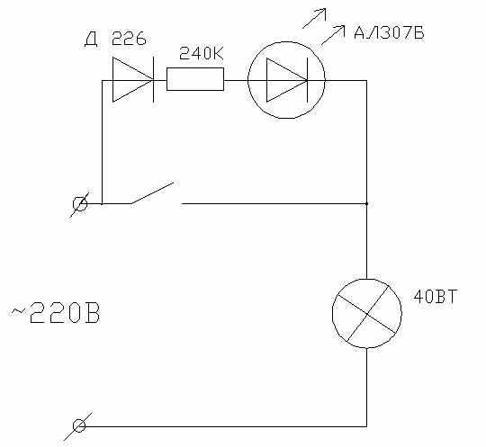
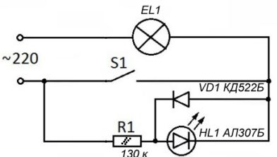
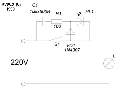
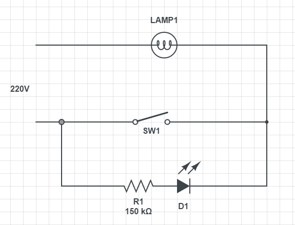
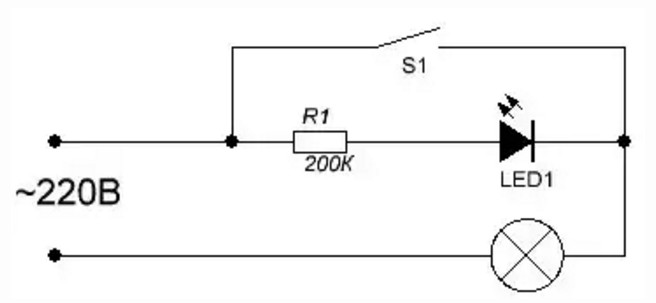
Another simple circuit showing how to connect LEDs to 220VAC is not much more complicated and can also be classified as a simple circuit.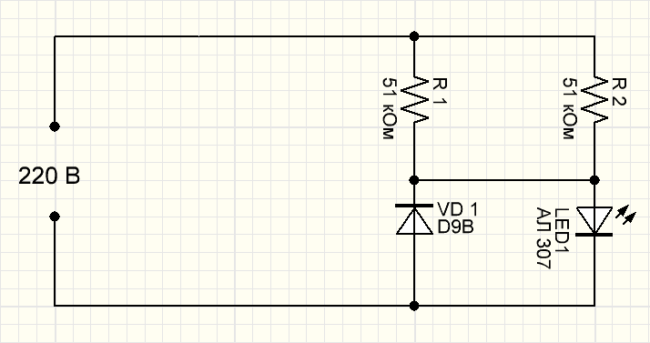
Consider the principle of operation. With a positive half-wave, current flows through resistors 1 and 2, as well as the LED itself. In this case, it is worth remembering that the voltage drop across the LED will be reversed for a conventional diode - VD1. As soon as the negative half-wave of 220 V "gets" into the circuit, the current will go through a conventional diode and resistors. In this case, the direct voltage drop across VD1 will be reversed with respect to the LED. Everything is simple.
With a positive half-wave of the mains voltage, the current flows through the resistors R1, R2 and the LED1 LED (in this case, the forward voltage drop on the LED1 LED is the reverse voltage for the VD1 diode). With a negative half-wave of the mains voltage, the current flows through the diode VD1 and resistors R1, R2 (in this case, the forward voltage drop across the VD1 diode is the reverse voltage for the LED1 LED).
Calculation part of the scheme
Rated mains voltage:
US.NOM = 220 V
The minimum and maximum mains voltage is accepted (experimental data):
US.MIN = 170 V
US.MAX = 250 V
The LED1 LED is accepted for installation, having the maximum allowable current:
ILED1.OPTION = 20 mA
Maximum rated peak current of LED1:
ILED1.AMPL.MAX = 0.7*ILED1.OPTION \u003d 0.7 * 20 \u003d 14 mA
Voltage drop across LED1 (experimental data):
ULED1 = 2 V
Minimum and maximum operating voltage across resistors R1, R2:
UR.ACT MIN = US.MIN = 170 V
UR.ACT MAX = US.MAX = 250 V
Estimated equivalent resistance of resistors R1, R2:
REQ.CALC = UR.AMPL.MAX/ILED1.AMPL.MAX = 350/14 = 25 kOhm
Maximum total power of resistors R1, R2:
PR.MAX = UR.ACT MAX2/REQ.CALC = 2502/25 = 2500mW = 2.5W
Estimated total power of resistors R1, R2:
PR.CALC = PR.MAX/0.7 = 2.5/0.7 = 3.6 W
A parallel connection of two resistors of the MLT-2 type is accepted, having a total maximum allowable power:
PR.DOP = 2 2 = 4 W
Estimated resistance of each resistor:
RCALC = 2*REQ.CALC \u003d 2 * 25 \u003d 50 kOhm
The nearest larger standard resistance of each resistor is taken:
R1 = R2 = 51 kΩ
Equivalent resistance of resistors R1, R2:
RECV = R1/2 = 51/2 = 26 kΩ
Maximum total power of resistors R1, R2:
PR.MAX = UR.ACT MAX2/RECV = 2502/26 = 2400 mW = 2.4 W


Minimum and maximum amplitude current of the HL1 LED and VD1 diode:
ILED1.AMPL.MIN = IVD1.AMPL.MIN = UR.AMPL.MIN/RECV = 240/26 = 9.2 mA
ILED1.AMPL.MAX = IVD1.AMPL.MAX = UR.AMPL.MAX/RECV = 350/26 = 13 mA
Minimum and maximum average current of HL1 LED and VD1 diode:
ILED1.WED.MIN = IVD1.SR.MIN = ILED1.ACT.MIN/TOF = 3.3/1.1 = 3.0 mA
ILED1.MED.MAX = IVD1.MED.MAX = ILED1.ACTUAL MAX/TOF = 4.8/1.1 = 4.4 mA
Reverse voltage diode VD1:
UVD1.OBR = ULED1.OL = 2 V
Design parameters of the diode VD1:
UVD1.CALC = UVD1.OBR/0.7 = 2/0.7 = 2.9 V
IVD1.CALC = UVD1.AMPL.MAX/0.7 = 13/0.7 = 19 mA
A VD1 diode of the D9V type is adopted, which has the following main parameters:
UVD1.DOP = 30 V
IVD1.DOP = 20 mA
I0.MAX = 250 uA
Cons of using the scheme for connecting LEDs to 220 V according to option 2
The main disadvantages of connecting LEDs according to this scheme are the low brightness of the LEDs, due to the low current. ILED1.SR = (3.0-4.4) mA and high power on resistors: R1, R2: PR.MAX = 2.4 W.
Connection
After studying the design of the circuit breaker, you can directly connect the circuit breaker. For those who first encountered such a task, it is recommended to draw up a diagram in advance, according to which wires will be laid to the switch and lighting fixtures.
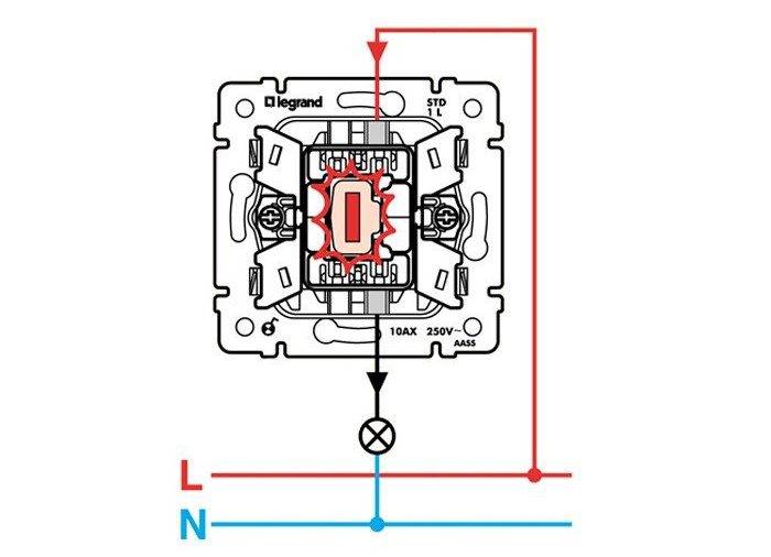
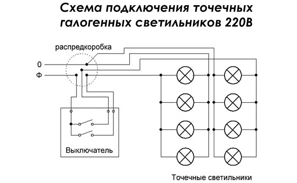
The standard wiring diagram includes a phase wire that is energized. It is indicated by the letter L and is connected to the lamp through the switch. In addition to it, there is a neutral or neutral wire N, which is connected directly to the lamp socket. If there is a ground wire, it is also connected directly to the luminaire.
Wires can be laid in a closed or open way, if this is provided for by the wiring diagram. In the first case, a strobe device in the walls will be required, in the second - corrugated pipes or cable channels. With hidden wiring under the switch, a hole is drilled in the wall.
In order to ensure a reliable connection and quality contact with the terminals, the end of each conductor is stripped by about 1-1.5 cm.When using stranded wires, it is recommended to crimp their ends. Three wires are connected to the two-gang switch. The first is phase and is fed to the input, and the second and third go to the output and are brought directly to the lamp. Zero and ground conductors are connected to the contacts of the light sources. The place of input of the phase wire is indicated by an arrow inside the switch. The phase itself is determined by the tester.
After all the wires are installed in their places and the double illuminated switch is connected, it is necessary to insulate potentially dangerous places. Then the whole structure, together with the wires, is installed in the mounting box and fixed with braces using screws. Upon completion of the main work, you need to install the decorative panel and both keys in place.
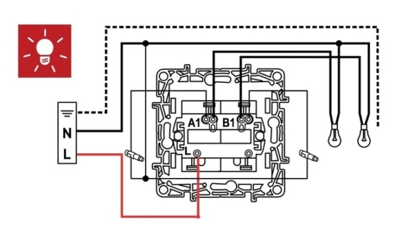
If there is a backlight, to connect a double switch, you must use additional wiring connected to mini-indicators mounted on the keys. One of them is connected to the phase at the input at the top, and the other is connected to one of the wires going to the fixtures. When the light is turned off, the colored indicators will continue to glow on each key.
Self assembly
If you know how to handle a soldering iron, understand electronics and have all the design details at your disposal, then you can assemble a touch switch for connecting to an LED strip, powered by a 220 volt network, with your own hands. The whole difficulty here lies in correctly soldering the circuit.The following is the simplest scheme that a beginner can handle.
Note! Capacitor C3 can be omitted from the circuit.
For assembly you will need the following parts:
Scheme for product assembly
- two transistors KT315;
- resistance (at 30 ohms);
- semiconductor D226;
- a simple capacitor (at 0.22 microfarads);
- power supply or a powerful battery with an output voltage of 9 volts;
- electrolytic capacitor (at 100 microfarads, 16 V).
All these components should be soldered according to the above scheme, placing it in a suitable case.
Illuminated switch device
If you remove the switch keys, then at the bottom you can see a small neon lamp - this is the backlight.
To understand how it works, consider the design of a backlit switch. And first, let's remember how the double switch works.


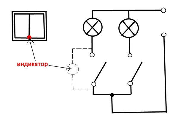


The phase coming to the switch is connected to the contact L, and from contacts L1 and L2 goes to lighting lamps, for example, a chandelier.
Movable switch contacts close between contacts L, L1 and L2:
1. L and L1 -> the first key is pressed; 2. L and L2 -> the second key is pressed; 3. L — L1 and L2 -> both keys are pressed.
Now it is clear why it is impossible to simultaneously connect “phase” and “zero” to the switch - there will be a short circuit.
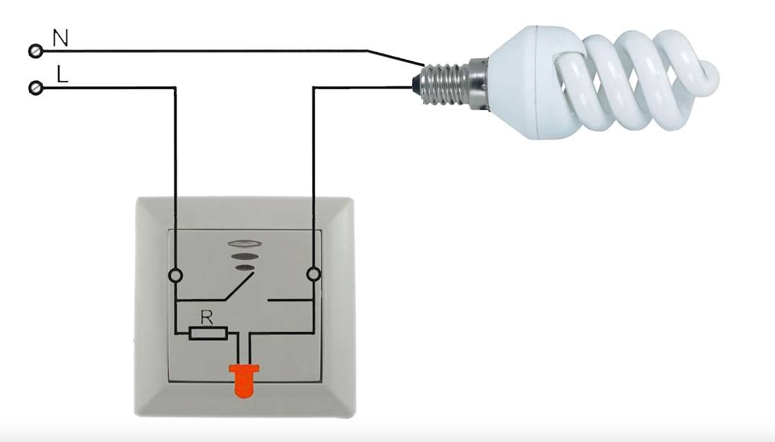
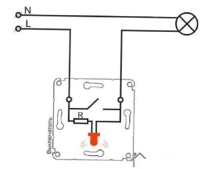
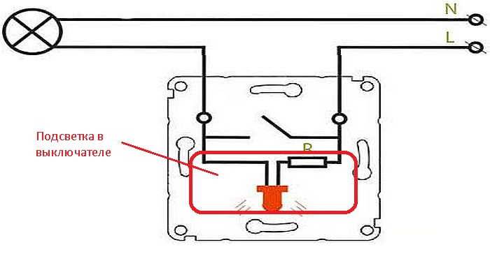
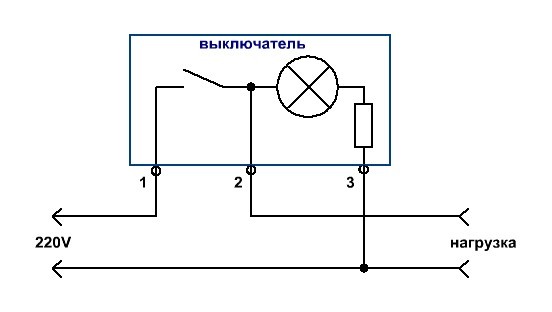
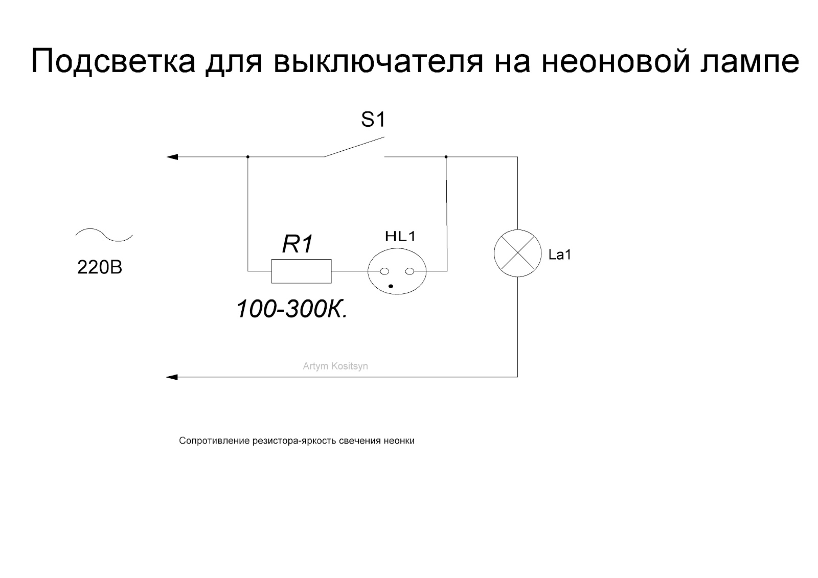
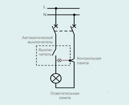
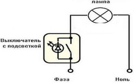
Here, a backlight circuit is installed on the switch, consisting of a current-limiting resistor and a neon light bulb. Bulb and resistor are soldered to the contacts L and L1.
The backlight circuit works like this:
While the light is off, the switch contacts L and L1 open, which means that the neon bulb will burn, since voltage comes to it through the filament of the lamp.
When the light is turned on, the movable contact of the switch closes to each other L and L1, thereby excluding the backlight circuit from the circuit. The lighting lamp lights up and the backlight goes out.
The question arises. And why doesn't the light bulb light up through the backlight? Everything is simple here.
To light a neon lamp, a small voltage and current is enough. In the backlight circuit, a current-limiting resistor is responsible for this, which dampens excess voltage. But for a lighting lamp, this voltage and current strength is not enough, so it does not light up.
When the switch is turned on, then through its contacts L and L1 phase directly comes to the lamp, bypassing the backlight chain.
Types of illuminated switches
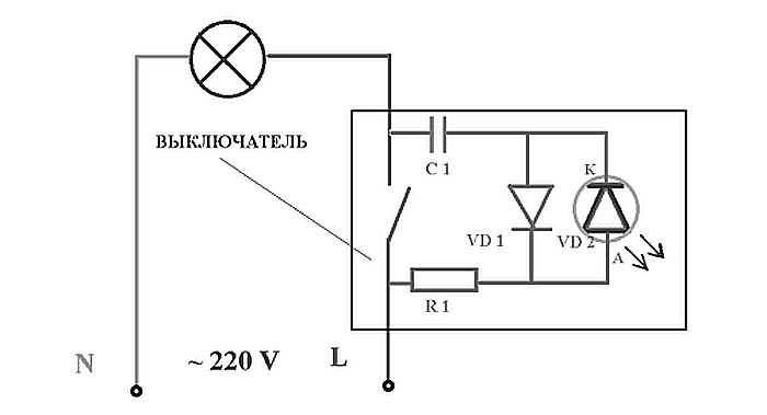
A common disadvantage of such devices is the inability to connect them to any fluorescent lamps equipped with starters. In this case, the capacitor through the LED will gradually charge, and when it reaches full charge, it will send all the accumulated electricity to the lamp. There is a short flash, which is periodically repeated and greatly irritates others.
The main criterion for choosing switches is the way they are turned on. The most widespread are standard keyboard devices designed for indoor and outdoor installation. Their design is extremely simple, and they are reliable and convenient in operation. Closing and opening of the circuit is carried out by means of a mechanical two-position switch.
Different models use LEDs as backlight. or neon lights. Despite the external similarity, they differ significantly in technical characteristics.For example, neon lamps have low power consumption, but they also contribute to a high voltage drop. That is, with a minimum glow current of 0.1 mA, the voltage drop is 70 V. For LEDs, these indicators will be 2 mA and 2 V, respectively.
The backlight can be installed not only in double switches, but also in devices with three and even four keys, as well as on walk-through models. A luminous dot is usually located on the case or on the keys - at the top, in the center or at the bottom.
Preparing to connect
The backlit switch is connected to the network in the same way as a normal one. The additional circuit does not affect the basic functions of the two-gang switch. A phase wire is connected to the device itself. This avoids the appearance of voltage on the lamp socket when the device is turned off. Zero wires, on the contrary, are connected directly to the lighting fixture. Before starting work, the electrical network must be de-energized by turning off the machine or unscrewing the safety plugs.
First, you should disassemble the switch to familiarize yourself with its design. Disassembly begins with keys secured with pins or plastic latches. Usually, they are pulled out with little effort, alternately - first one, and then the other.
After the keys, the case is released from the decorative frame. Its fastening is carried out with two screws that are easily unscrewed. When all plastic parts are removed, the electrical part of the device becomes completely open for viewing. Immediately you need to determine the location of the terminals where the wires will be connected. The terminals themselves are equipped in the form of small copper pads with clamping screws.The wire is cleaned of insulation, inserted into its place and pressed with a screw.
If there is a backlight, it is necessary to strip the wire and insert it into the desired spring connector. The internal spring at the same time provides reliable fixation and high-quality contact.
Connection methods
Connecting the LED strip to the power supply in series
Therefore, we pay attention to polarity: we connect “+” only to the same pole, and “-” to minus
At the end of the tape, which comes on a reel, conductors are soldered. If the glow is monochrome, there are two conductors - "+" and "-", for multi-color 4, - one common "positive" (+ V) and three colored ones (R - red, G - green, B - blue).
Bobbins in their purest form
But a 5-meter piece is not always needed. shorter lengths are often required. Cut the tape along the marked lines.


Cutting lines on LED strips
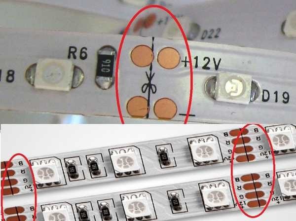
In the photo you can see contact pads on both sides of the cut line. They are signed on each tape, so it’s quite difficult to get confused when connecting. To make it even easier, use conductors of different colors. So it will be clearer and you definitely will not get confused.
Connectors
You can connect the LED strip without soldering. There are special connectors for this. These are specially designed devices - plastic cases that provide proper contact. There are connectors:
- for connection to the conductor strip;
- connection of two tapes. Different types of connectors
Everything is very simple: the cover is opened, a tape or conductors with bare ends are inserted. The lid closes. The connection is ready.
The method is very simple, but not very reliable.Contact is only provided by pressure, and if the cover is loosened a little, problems begin.
Soldering
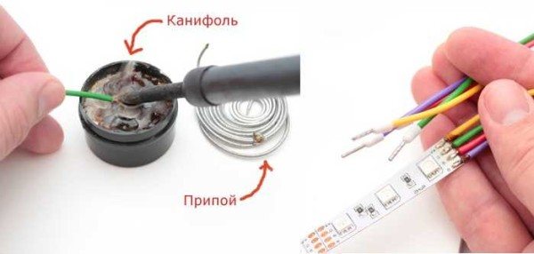
If you have at least some soldering skills, it is better to use this method. To work, you will need a medium-power soldering iron, with a thin or sharpened tip. You need rosin or flux, as well as tin or solder.
We clean the ends of the conductors from the insulation, twist them into a tight bundle. We take a heated soldering iron, lay the conductor on the rosin, warm it up. We take a little solder on the tip of the soldering iron, we warm up the wires again. The veins should be tightened with tin - tinned. In this form, the conductors are easy to solder.
How to connect a diode tape
Similarly, it is desirable to lubricate the contact pads: dip the soldering iron in rosin, warm up the pad. Make sure that the tin does not leak out of the platforms. Take the prepared conductor, lay it on the platform, warm it up with a soldering iron. The tin should melt and tighten the conductor. Hold the conductor in place for 10-20 seconds (sometimes it is easier to hold it with thin-nosed pliers or tweezers - the conductor heats up), pull. He must hold on tight. We solder all the necessary conductors in the same way.
ON RGB strips with 4 wires, be careful not to connect the pads during soldering. The distance between the contacts is very small, the slightest streaks can ruin the whole thing. Act carefully.
Watch the process of soldering the diode tape in the video. You will need to repeat everything.
DIY illuminated switch
During the operation of electrical equipment, it sometimes turns out that in some of the rooms it would be nice to have a switch backlight. To do this, it is not necessary to buy a device - you can independently improve the old one.
What is needed for this:
- conventional switch;
- LED with any characteristics;
- 470 kΩ resistor;
- diode 0.25 W;
- the wire;
- soldering iron;
- drill.
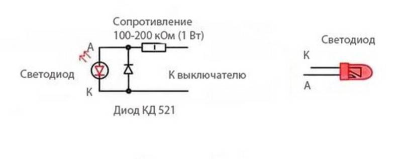
Using a soldering iron, begin to assemble the circuit. The cathode of the diode (marked with a black stripe) is connected to the anode of the LED (the anode has a longer leg). The resistor is soldered to the positive terminal of the LED and to the wire that will serve as the connection to the switch. The second wire is connected to the cathode of the LED.
If there is no resistor of suitable power at hand or there is not enough space for placement, then it can be replaced with two resistors of lower power by connecting them in series (+)
Next, connect everything to the on-off mechanism. The phase conductor that leads to the lamp is connected to the terminal along with one of the wires leading to the LED. The other wiring is connected to the input terminal along with the phase wire, which supplies current from the mains.
It is necessary to carefully insulate the exposed sections of the wire and prevent the conductors from touching the case, this is especially important to do if it is metal. They check the connection diagram of the backlit switch for operability as follows: the key, closing the contact, causes the chandelier or lamp to light up, in the off state the LED lamp lights up
If the circuit is working correctly, you can install the fixture in the case
The connection diagram of the backlit switch is checked for operability as follows: the key, closing the contact, causes the chandelier or lamp to light up, and the LED lamp lights up when off. If the circuit is working correctly, you can install the fixture in the case.
In order to see the lighting, the LED lamp is led out into the drilled hole at the top of the housing.It is not necessary to do this if the case is light - the light will break through it.
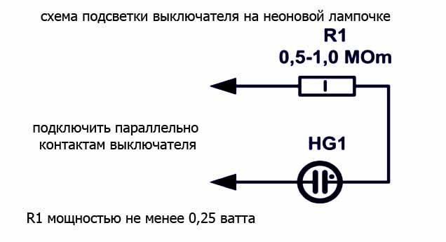
The switch can be illuminated with a neon lamp. The circuit uses a HG1 gas discharge lamp and any type of resistance with a nominal value of 0.5-1.0 MΩ with a power of more than 0.25 W (+)
"Horror stories" and myths about the light switch
To understand the so-called "problem", consider the different types of indication. It comes in neon and LED. There is no fundamental difference in power consumption, both circuits consume no more than 1 W of power. Neons come in two colors: orange (red) or green, depending on the gas in the flask. The LED can be of any color, even dynamically changing hue (RGB).


Now for the myths:
- Additional electricity consumption. To some extent, this statement is true. The LED backlight circuit consumes about 1W of power. For a month, it accumulates 0.5–0.7 kilowatt / hour. That is, you will have to pay a couple of rubles for comfort (from each switch). Similar costs for a neon lamp. There, energy is spent mainly on a limiting resistor.
- “We installed the backlight - now the switched off lamps are burning in the dark!” And it is true. Old-style lamps (incandescent and halogen) regularly go out when turned off. But no one uses them anymore. The problem concerns economical fluorescent discharge lamps (they flash intermittently), and LED lamps with an inexpensive control circuit (low glow).
The first option is gradually becoming irrelevant.

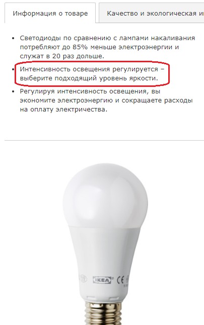
LED lamps are constantly getting cheaper, the only advantage of housekeepers (price) is lost.As for LED lamps, you can buy more expensive ones with a dimmable power supply. Such lamps can change the brightness of the glow when connected through a regulator: the so-called "dimmer". At the same time, the issue of parasitic glow in the power supply is resolved if a backlit switch is used.
Information about this is in the instructions for the lamp.
If the first myth (additional energy consumption) must be put up with: you just pay a small amount for convenience, then the second “problem” has several solutions. You will learn about this from our material.
Connection rules
Regardless of the type, the installation of a backlit switch is the same. The differences are only in a couple of nuances.
Installation of a single switch
The easiest way is to connect a single-gang (single) backlit switch. First of all, you need to turn off the power and remove the old switch.
For this:
Remove the key using a flathead screwdriver.
Carefully remove the decorative trim.
Unscrew the screws connecting the device to the socket. Pull it out.
Loosen the fasteners, disconnect the wires .. At the end of the manipulations, the inside of the dismantled switch remains on the hands
It is thrown away or used as a spare part.
At the end of the manipulations, the inside of the dismantled switch remains on the hands. It is thrown away or used as spare parts.
To install a new light switch with indicator / backlight, you must repeat the above steps, only in reverse order:
- Insert the "insides" into the socket, not forgetting to attach the wires to the switch contacts.
- Screw in the bolts.
- Install a decorative frame.
- Insert key.
- Turn on the power to check the correct installation and connection. If the work is done correctly, the diode in the backlight will light up.
Installation and connection of switches with several keys
Connecting a double or triple illuminated switch is carried out in much the same way. To install a design with two keys, you will need a screwdriver, side cutters, tips and an indicator with which to determine the phase.
The work is done like this:
As in the previous case, first of all it is necessary to de-energize the apartment / house. Next, the dismantling of the old device begins.
Remove the keys and unscrew the screws. There will be three wires in the socket. One is the incoming power, two more are the power going to the lighting fixture.
Now, using an indicator screwdriver, you need to find the phase wire, mark it or just remember
You need to act very carefully, because this stage requires the presence of voltage in the network.
De-energize the network.
Strip wires from insulation.
Get a new device. It has three contact groups and a pair of wires coming from the backlight.
Using a measuring device, determine the "Off" position.
Usually, the wires coming from the LED have special contact plates for the screws. The screw must be unscrewed, attached to the plate and screwed back. Repeat the action for other contacts.
Attach the phase wire to the plate, located separately from the others, with a screw.
Connect the wire going to the chandelier to the contact and fix it.
Fasten the last wire under the contact on which there are no plates.
Check if the connection is correct.
Insert the inside of the switch into the junction box.
Fasten the screws.
Reinstall the keys.
After the installation is completed, connect the power supply and check the operation of the device.

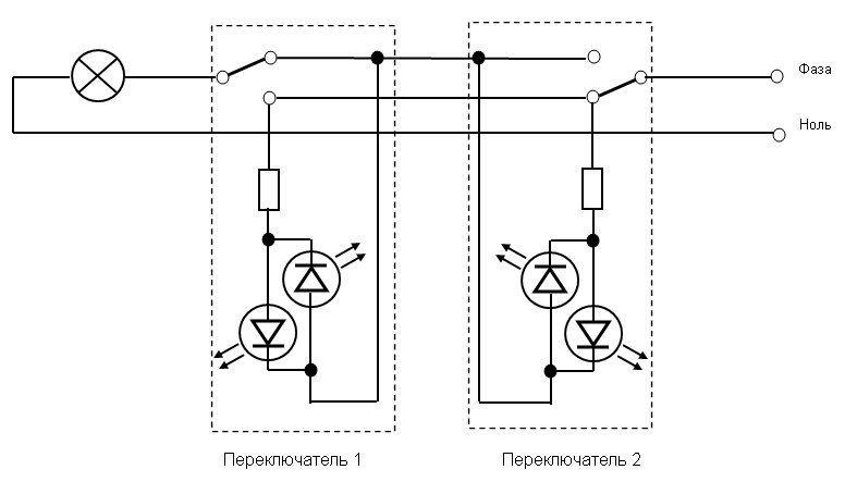
If it is necessary to control the light source from different places, a pass / toggle switch should be installed. Its main difference from classical models is the presence of a movable contact. If you press the on / off key, it will be transferred from one contact to another, starting the work of the second circuit.
Connecting a backlit switch
The connection diagram of the pass-through switch is extremely simple. Two separate devices are installed on both sides of the chain.
To do this, you will need to lay a three-core cable to one and to the other. When the first switch is turned on, the circuit will be closed and the lamp will be on. When you turn on the second light will turn off.
How to combine lamps and a switch
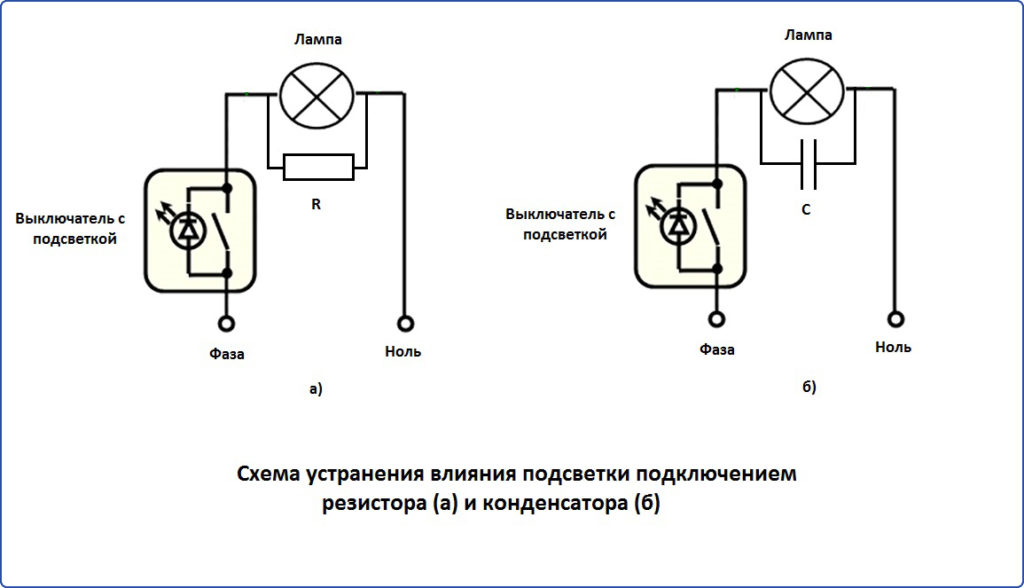
If the fluorescent lamp flickers or glows faintly after turning it off, the problem can be solved by connecting an additional resistance (resistor or capacitor) in parallel with the lighting point.
To do this, you need a resistor with a nominal value of 50 kOhm and a power of 2 watts. It will absorb excess current when the backlight is on and will not allow the lamp capacitor to charge.


 The resistor is placed in a junction box in a ceiling lamp or chandelier cartridge, having previously connected it to two wires and insulating the bare areas. Heat shrink tubing can be used for insulation (+)
This method of eliminating the cause of flashing energy-saving lamps is considered quite dangerous and experienced electricians do not recommend using it without sufficient skills in electrical work.
It is better to use a ready-made protection unit for fluorescent and LED lamps, which eliminates flicker, protects against power surges, and eliminates interference from lamps. Its connection is mandatory if a lighted switch is used.
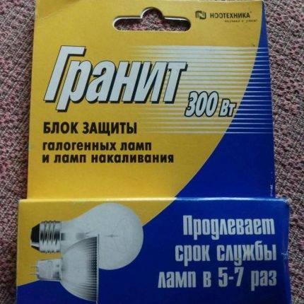 The maximum lamp power when using the GRANITE BZ-300-L block is 300 W. The protection is triggered when the mains voltage is 275-300 W
The protective unit is connected in parallel with lamps that do not work correctly - flicker or dimly glow when turned off. Install it in the body of the lamp or in the glass of the chandelier.
When using lighting fixtures with two or more lighting groups, a separate block (+) is installed on each of the groups
Solutions to popular problems and malfunctions of LED lamps are detailed in these articles:
- Why LED lamps are on when the switch is off: causes and solutions
- Why LED lights blink: troubleshooting + how to fix
- Do-it-yourself LED lamp repair: causes of breakdowns, when and how you can repair it yourself


