- Three-point light switching circuit
- Where is the switch used?
- Basic connection errors
- Changing a conventional switch under the gate
- Switch wiring method
- Screw type clamp
- Non-screw clamp
- Well-known manufacturers of electrical feed-through switches
- Varieties of switches
- Keyboards
- Swivel cross
- The appearance of the rotary switches (photo gallery)
- Overhead and built-in
- Characteristics of cross switches
- Main characteristics
- Wiring Features
- Well-known manufacturers of electrical feed-through switches
- Self connection
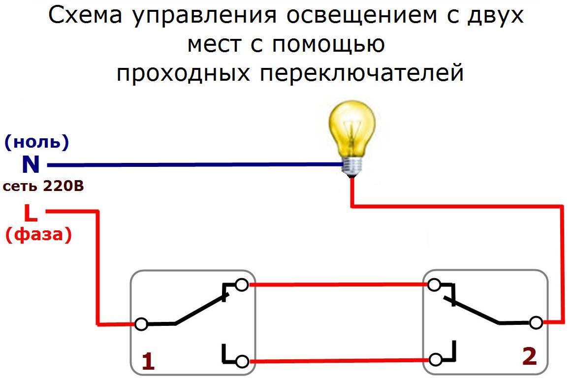
- Why are pass switches needed?
- Some subtleties
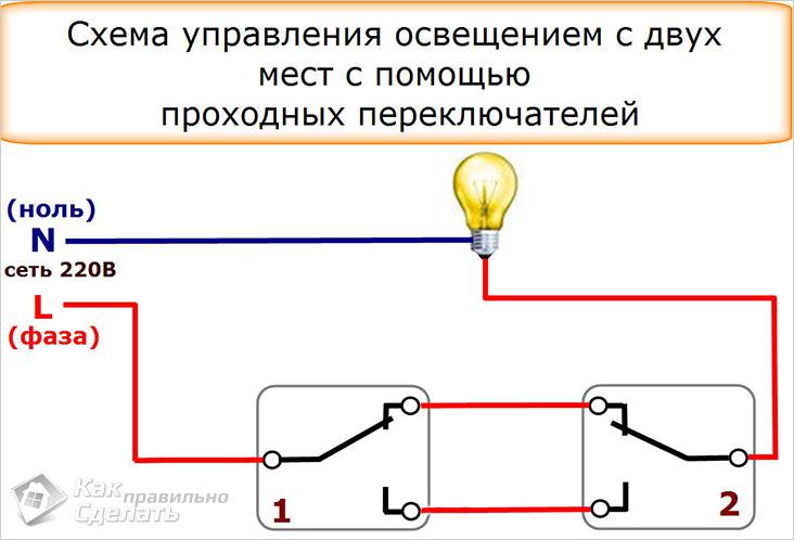
- Why might you need a PV light circuit for 2 switches?
- Lighting control scheme from 3 places
- feed-through mounting and cross switches
- detach action
- Conclusions and useful video on the topic
Three-point light switching circuit
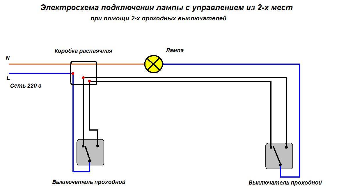
In the previous section, switching on and off electricity from two points was considered: the circuit is very simple.
Well, if you need to turn on/off the light from three points? Such a problem arises when trying to save light in a multi-storey building and at the same time not walk up the stairs in the dark. There is nothing difficult in this.But you will need an additional switch, and not a pass-through, but a cross one.
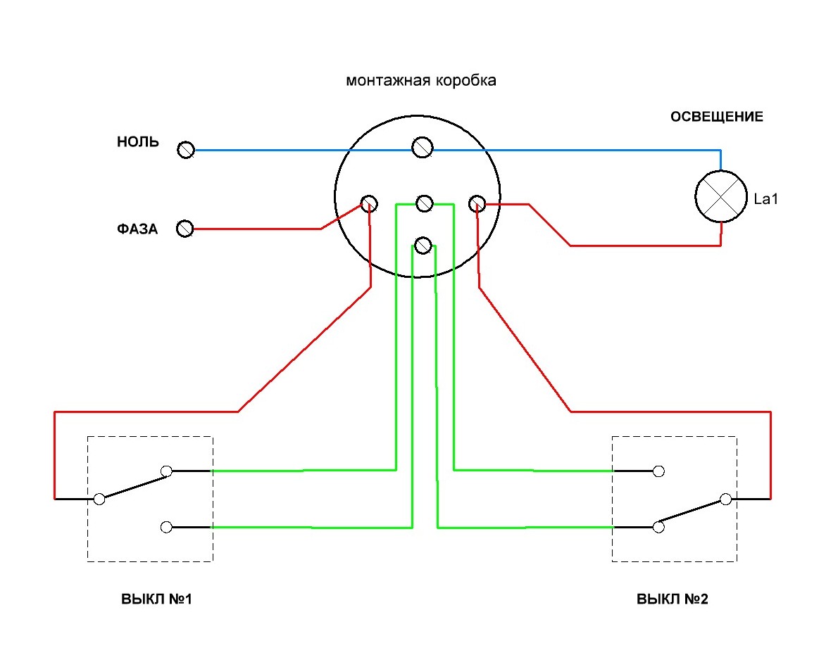
Rice. 3 Cross switch circuit
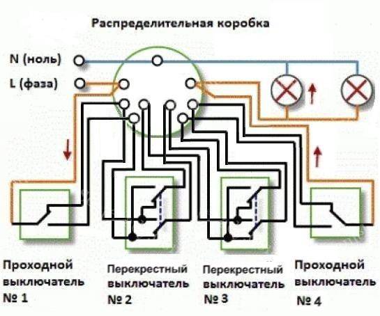
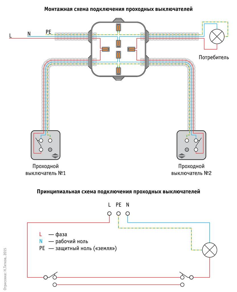
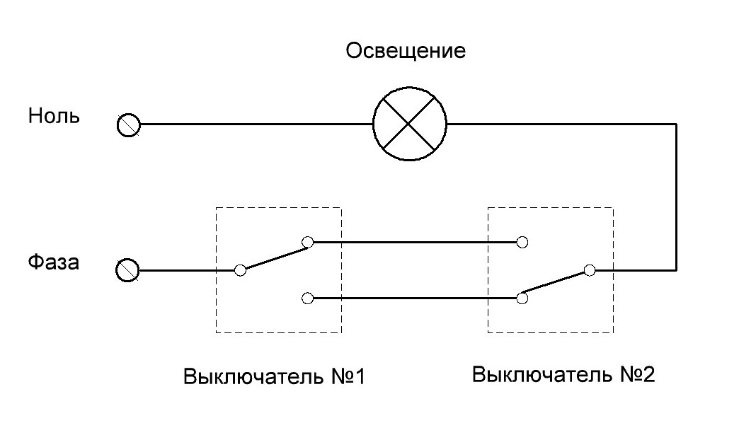
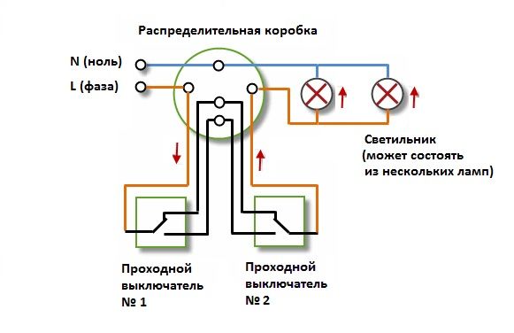
With a crossover switch, phase can be transferred from any input to any output, and the circuit can be disconnected between any input-output pair. Using a cross switch and two pass-through switches, you can assemble a light on / off circuit from those points, for example, on a staircase in a three-story house:
Fig. 4 Scheme of turning on / off the light from three points
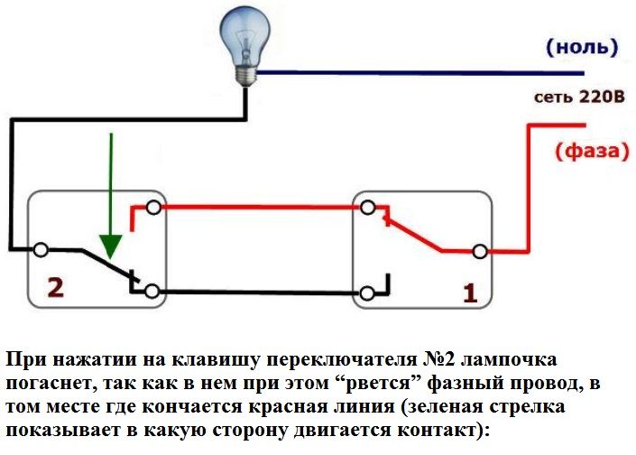
Figure 4 shows the position of the switches in which the light is on. By clicking a key on any of those switches, we turn off the light. After that, it is worth pressing a key on any switch - the light will light up.
And if the floors are not three, but five, six? You can assemble the circuit so that the light will turn on and off from any floor.
Only two switches are always needed: at the beginning and end of the chain. Between them put cross switches. An example of a diagram for a four-story staircase is shown in Fig. 5.
Rice. 5. Scheme of turning on / off the light from four points
Armed with pencil and paper, you can draw different options and make sure that pressing any key on any switch leads to a change in the situation: the light goes out, and if the light was off, it lights up.
This wonderful circuit can grow as more cross switches are added to it.
No matter how many cross switches with four contacts, there should be only two pass-through switches: at the beginning and at the end.
Where is the switch used?
In addition to organizations, as mentioned above, such a solution is relevant for flights of stairs, with the addition of a time relay.However, the relay is designed for a certain amount of time, regardless of whether the person managed to climb the stairs or not. This means that the system with the addition of a temporary sensor is not very convenient, although in general the switches make life much easier.
Thus, in order to illuminate the flight of stairs for 4 floors, it is enough to press the switch on the first one. And upon completion of the movement up the stairs, turn off all the lamps with one click on the top floor.
Basic connection errors
The most common mistake is made at the stage of determining the common terminal. Some users believe that regardless of the scheme, the correct link will be where there is only one contact. The circuit assembled in this way does not work correctly, the switches in it depend on each other
In this case, it is important to remember that on switches from different manufacturers, the common terminal may be located in different places. Therefore, you should always check the provided diagram or call the links with a tester.
If everything is done correctly, and the circuit still does not work correctly, then the reason may be the wrong choice of switch, perhaps just 2 standard devices are installed on the network.
The next popular installation error is the incorrect introduction of intermediate devices into the circuit. Often 2 wires from switch #1 are connected to the input, and from switch #2 both to the output. The circuit will not work, since the contacts must be connected crosswise. For such walk-through electrical switches, the connection diagram is almost always indicated on the device itself.
Changing a conventional switch under the gate
When studying a photo of a pass-through switch in the network, it becomes clear that the differences of this type from the usual one are minimal. And therefore, if there are a couple of ordinary elements in stock, they can be easily converted into an improved look. Especially when it comes to existing devices. Thus, it will be possible to save not only on the cost of electricity, but also on the purchase of additional devices.
The instruction on how to make a pass-through switch from a standard one implies the presence of a pair of switching devices manufactured by the same company and one release format (key shape, size, color). Moreover, you will need a single-key and two-key varieties.


It is important to pay attention here that the two-key type of device has terminals that allow changing places. This is important to ensure an independent process of closing and opening the network. In other words, in one position of the key, the first network will be turned on, in another position, the second one.
In other words, in one position of the key, the first network will be turned on, in another position, the second one.
The algorithm of actions will look like:
- at the point of attachment with a probe, determine which of the wires running in the wall (over the wall) is the phase wire and mark it with a color, this will facilitate the installation process;
- if the element is active, and not new, you will need to de-energize it and remove it (loosen the contact clamps and each socket screw);
- on the reverse side of the removed device, open the clamps on the case and remove the electrical component;
- using a thick screwdriver (slotted type), the spring pushers are carefully removed from the frame to avoid damage to the elements;
- the same screwdriver pry the teeth on the ends of the extracted mechanism;
- one of the moving rocker contacts located on the electrical part will need to be turned a full turn (180 °);
- cut off one of the common contact areas (without subsequent insulation);
- return the removed elements to their place;
- if we are talking about an active element, you will need to install it in its original place;
- remove the key from the single-key switch and put it on the assembled structure;
- install the second switch on the planned control point, connecting it to the first three-wire cable;
- connect the circuit together in a junction box.
In the case of switches installed during repair, the presence of an improved switch can be taken into account in the design. If we are talking about an autonomous alteration of control points for an electrical device, the process will be more complicated.
At first, after installing the considered types of switches, whether they are from the factory or made independently, there may be confusion in use due to some features of the devices, since it will no longer be clear by the position of the key whether the device is on or off.
Also, the network will not be available simultaneously from both (all) points of control. At one point in time, the command must be given from one point. However, the initial unfamiliarity will not override the benefits of the installation.
Switch wiring method
Before starting the installation of the switch, you need to know that the internal wire attachments in the device may be different. There are two switching methods.
Screw type clamp
The screw type contact is tightened with a screwdriver.Preliminarily, about 2 cm of the wire is cleaned of insulation, then it is located under the terminal and fixed
It is extremely important that not a millimeter of insulation remains under the terminal, otherwise it will begin to melt, which is very dangerous.
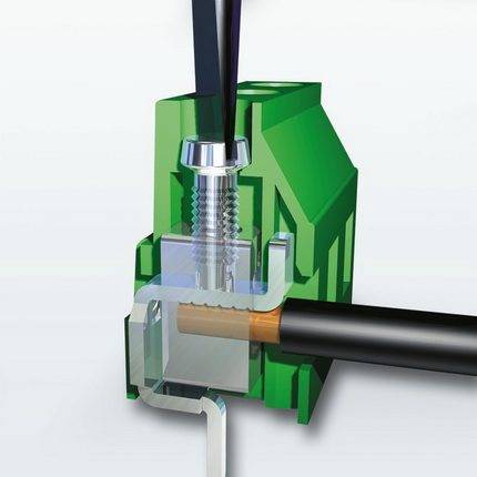 The screw-type clamp is best used for aluminum wires, which tend to heat up and deform. To return to working capacity, it will be enough to tighten the contact (+)
This connection is especially good for aluminum wires. They heat up during operation, which eventually leads to deformation. The contact in this case begins to warm up and spark.


To solve the problem, it will be enough to tighten the screw. The wires sandwiched between the two flat contact plates will "fall into place" and the device will operate without heat or sparks.
Non-screw clamp
Represents contact with the pressure plate. Equipped with a special button that adjusts the position of the plate. The wire is stripped of insulation by 1 cm, after which it is inserted into the contact hole and clamped. The whole procedure is very fast and easy.
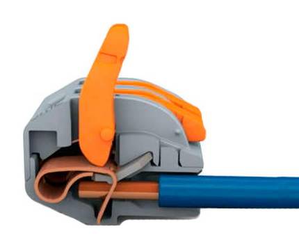
The non-screw terminal is extremely easy to install, which is why experts recommend that novice electricians work with terminals of this type.
The design of the terminal ensures high reliability of the resulting connection. Non-screw terminals are best used for copper wiring.
It must be admitted that screw and non-screw clamps provide approximately the same reliability and quality of connections. However, the second option is easier to install. It is his experienced experts who recommend using it to novice electricians.
Well-known manufacturers of electrical feed-through switches
The most common switches are products of the brand Legrand (Legrand). The switches are made of high-quality materials, have a stylish laconic design, are easy to install and are famous for their flexible pricing policy. The lineup has a lot of offers - from cheap to expensive options. Among the shortcomings, users attributed the need to adjust the installation site.
Lezard is a subsidiary of Legrand located in China. From the parent, Lezard inherited only the design, the quality of the products and materials used is significantly different from the original.
Another major player in the market is the Wessen brand, which is part of the Schneider Electric group of companies. Switches are manufactured according to the latest developments on new equipment and comply with European quality standards. The devices provide for the replacement of the switch frame without complete dismantling.
Makel, a Turkish manufacturer of indoor electrical networking devices, has been supplying the market with high-quality and safe switches for many years, which, on top of everything, have a stylish design. Engineers have developed the ability to connect devices without interfering with the junction box, which facilitates the installation process and guarantees the safety of further operation.
Varieties of switches
According to their design, cross switches are divided into 2 types: keyboard and rotary.
Keyboards
Switches of this type are used most often.
Key switches, it is more correct to call them switches, break one circuit and close another. Conventional switches only open or close one circuit.Outwardly, they practically do not differ. They can only be distinguished from the back by the number of contacts:
- a conventional single-key has 2 contacts;
- at the checkpoint -3;
- at the cross - 4.
Key switches can have 1, 2 or 3 keys. Multi-key switches are designed to independently control multiple circuits.
Swivel cross
Switches of this type are installed less frequently than keyboards. Usually they are used in warehouses and industrial premises, for street lighting, as an interior decoration in apartments. The contact groups in them are closed and opened by turning the lever.
The appearance of the rotary switches (photo gallery)
Overhead and built-in
According to the installation method, switches are divided into 2 types: overhead and built-in.
Built-in switches are mounted at the stage of construction or repair in boxes installed in niches. The wires are laid in stubs or attached to the walls. Typically, this method is used before plastering walls or facing them with drywall or other materials.
Overhead switches and wires suitable for them are attached to the wall. In this case, there is no need to scratch the walls and knock out recesses for the boxes. In this way they are usually mounted during cosmetic repairs. Overhead switches create certain inconveniences: dust accumulates on them, people cling to them while driving. In some cases, the owners, on the contrary, prefer this type of switch for interior design.
Characteristics of cross switches
On the market of electrical products there is a wide choice of switches and switches of domestic and foreign manufacturers.The difference in price between different manufacturers is significant, and the dimensions and technical characteristics are similar.
Main characteristics
| Voltage | 220–230 V |
| Current strength | 10 A |
| Material corps | thermoplastic polycarbonate plastic |
Models with housings that protect against moisture and steam are more expensive.
Wiring Features
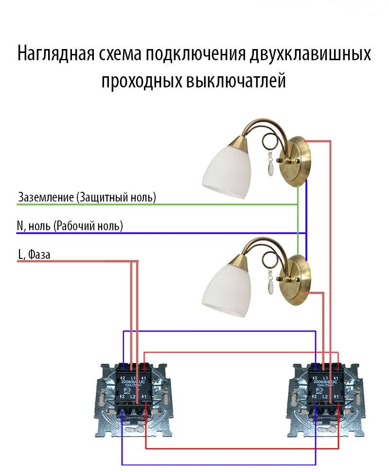
The connection diagram of the switch, depending on its type (the number of keys is taken into account), varies slightly.

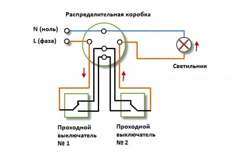
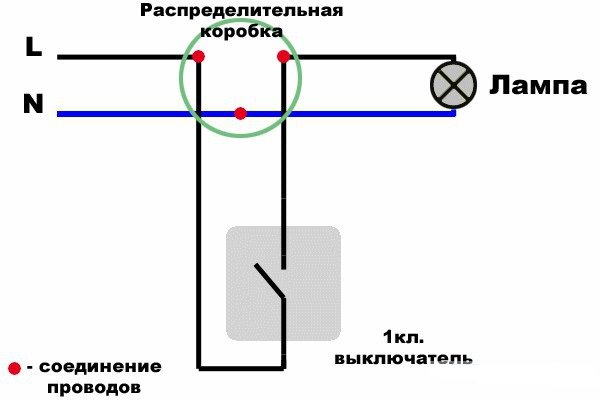
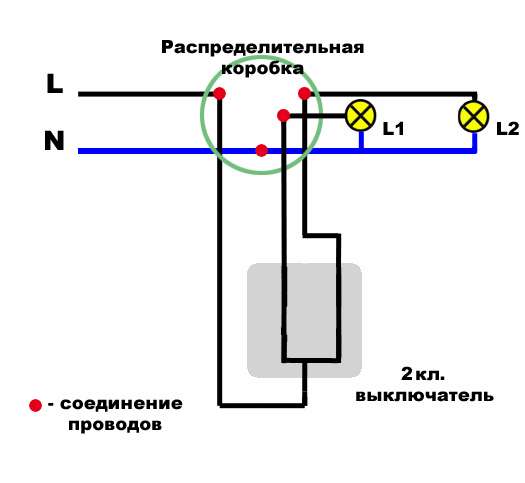
The simplest option is to connect a single-gang switch, in which case you can do everything yourself. In such a situation, in the distribution box, there are only 2 wires - zero and phase.


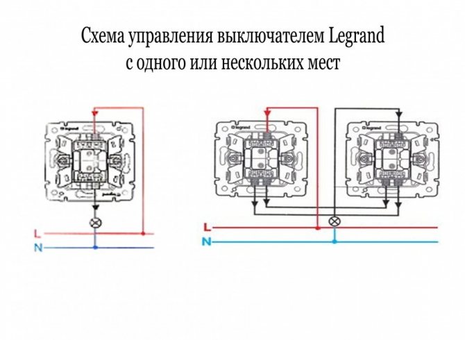


The blue wire (zero) is connected to the same wire on the lamp. The input phase initially moves to the device to turn off the light, after which it returns to the distribution box again, and only then it is connected to the phase from the light bulb.
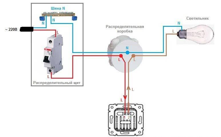
The main condition for connecting a single-key light switch is attentiveness, because even with only two wires, situations are quite common when a person confuses the wires.
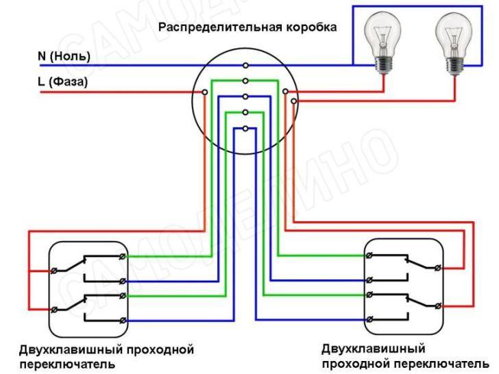
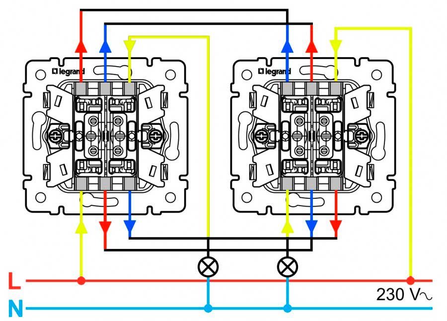
Connecting a two-gang switch will require great knowledge of electricians, this is justified by the fact that all groups of lamps have a separate circuit break. As with a single-key unit, there are two cores in the distribution box. The blue wire is connected to other wires of the same color at the input.


The phase is initially carried out on a break, on both buttons, then it is fixed in a predetermined recess. Outgoing wires go to each group of lighting fixtures present or to two individual light bulbs.

Be sure to take into account the fact that the back of the case contains three holes: two are located on the left side, and one more on the right. Where there is only one hole, the input phase is connected, and where there are two holes, the output phase is connected to the lamp.

The input phase is sent to break, and after that it is divided into three different phase conductors, each of which is sent to its own group of light bulbs.

Well-known manufacturers of electrical feed-through switches
The most common switches are products of the brand Legrand (Legrand). The switches are made of high-quality materials, have a stylish laconic design, are easy to install and are famous for their flexible pricing policy. The lineup has a lot of offers - from cheap to expensive options. Among the shortcomings, users attributed the need to adjust the installation site.
Lezard is a subsidiary of Legrand located in China. From the parent, Lezard inherited only the design, the quality of the products and materials used is significantly different from the original.
Another major player in the market is the Wessen brand, which is part of the Schneider Electric group of companies. Switches are manufactured according to the latest developments on new equipment and comply with European quality standards. The devices provide for the replacement of the switch frame without complete dismantling.
Makel, a Turkish manufacturer of indoor electrical networking devices, has been supplying the market with high-quality and safe switches for many years, which, on top of everything, have a stylish design.Engineers have developed the ability to connect devices without interfering with the junction box, which facilitates the installation process and guarantees the safety of further operation.
HelpfulUseless
Self connection
Connecting a single-gang switch
To connect a single-key or two-key switch, you will need to first prepare the tools and materials in accordance with the following list:
- knife with a sharp blade;
- wire cutters;
- screwdrivers of various types;
- pliers;
- contact with an insulator;
- insulating tape;
- wires;
- junction box;
After all the preparations are completed, you can begin the installation process.
To install a single-key switch, you will need to reproduce the following algorithm of actions:
At the initial stage, it is necessary to install the junction box and securely fix it on the wall, if this element was not previously available.
A three-core wire is pulled from the installed box to the socket, and on both sides there must be a margin of at least 15 cm, which will be required to further connect the device.
The second wire is also laid from the junction box, but extends to the lighting fixture.
The third stretched wire will serve to provide power to the box, it is pulled to it from the machine.
The fourth and last wire is pulled to the machine itself from the electrical panel with an energy meter, or from the introductory machine. However, if there is already a power wire, then this step should be skipped, and the previously drawn cable should be de-energized in order to protect yourself from accidents during the installation process.
Connect a system responsible for safety during the operation of the feed-through switch, for example, a multi-pole circuit breaker or a special device that limits the incoming voltage.
On the wires, with a knife, the first protective layer is cut off, and the insulation is also removed. After that, the phase and neutral wires are connected to the circuit breaker. The cores of the wires are fixed on the terminals of the machine, after which they are clamped using special clamping screws.
According to the exact same scheme, all the wires going to the distribution box are connected


At this stage, it is important to observe the correct technology for connecting wires. To do this, you need to focus on their colors: the phase and the insulator are connected to the terminals located in the same way as in the previous connection
In other words, if before that the neutral wire was connected on the left side, then here it must be repeated, its connection to the right, instead of the phase, is unacceptable.
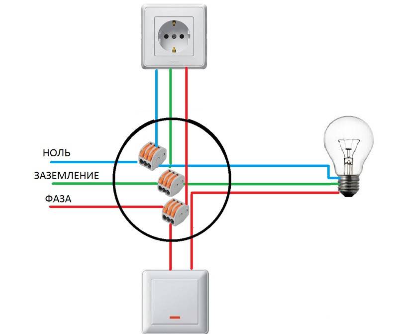
If the lighting system has some features, for example, a light source with metal elements is planned to be installed in the kitchen or in the bathroom, where there is always high humidity, then grounding must also be considered. Its functions will be performed by the third wire, it must be connected to both the incoming and outgoing contacts using the contact clamp.
At this stage, you can go directly to connecting the lighting fixture, the ground wire is not required in most cases, but in any case, it is not recommended to cut it off, as it may be needed in the future. The remaining wires are prepared according to the scheme described above, after which they are connected to the cartridge of the device.
An unused ground wire can be insulated and then placed inside the socket.
Most modern models of walk-through switches are equipped with plug-in contacts, which greatly facilitates the connection process. The contact corresponding to the incoming phase is traditionally indicated by the Latin letter L, and the outgoing phase has an icon in the form of an arrow pointing down. The phase wire must be connected exactly to the L contact, and the neutral wire must be connected to the outgoing phase with an arrow.
It remains only to place the connected switch device in the socket, after which the process can be considered completely completed.
Connecting a two-gang switch
A number of nuances arise if you plan to connect a two-gang pass-through switch. In fact, there is nothing complicated about this, since there are no fundamental differences in the schemes.
The connection of such a device is carried out using a double single-key switch circuit, which is described in detail above. In simple terms, each of the keys of such a device will be equal to connecting two independent single-key switches.
The number of wires used increases in proportion to the growth of the keys used, otherwise, the connection technology remains unchanged.
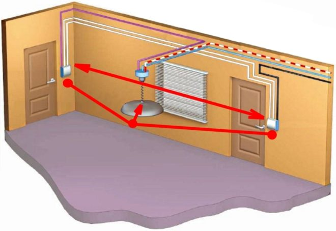
Why are pass switches needed?
Turning on the light in a long dark hallway can be quite inconvenient if there is only one switch located at the end of the room. The most rational installation of pass-through switches (another name is cross switches) in different sides of the room.
So it will be possible to turn on, turn off the light immediately after entering the corridor.This is especially true in the entrance of the house, where the apartments are located in one line along a long landing, on flights of stairs, in offices, industrial premises.
Another use case for such a control scheme is a large bedroom with several beds. If you install walk-through switches at each bed, you can turn on the light without getting up. The installation of such devices is justified in summer cottages, personal plots, courtyards of private houses. You can turn on the light at the exit from the house - after the completion of business there is no need to go in the dark.
Some subtleties
If it is required to create several intermediate control points for lighting fixtures, for example, for flights of stairs of the entrance of a five-story building, then all of them are switched on sequentially to each other. The same phase must pass through them - this is a prerequisite.
There is an opinion that for the installation of intermediate on-off points for lighting fixtures, it is worth using only a four-core cable. This simplifies installation work.
There is some truth in this, but there is a real threat to include wire of improper section in the line. This is because cables with so many conductors are designed for three-phase current, the fourth core in them is one third smaller in diameter, it is connected to the ground loop. Phase current cannot be passed through it.
All work on connecting an additional on-off point is carried out with the voltage removed and in compliance with other electrical safety measures.
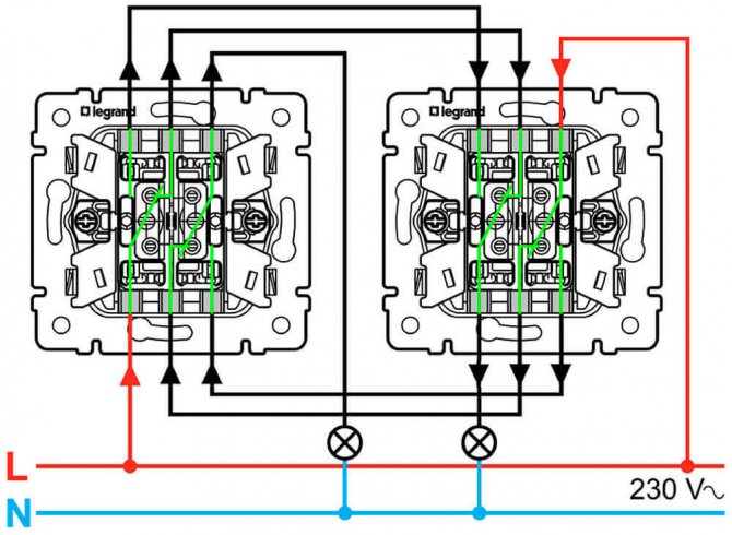
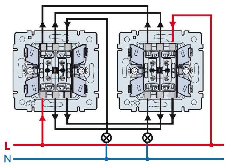
Wiring diagram for through and cross switches from 3 places:
Why might you need a PV light circuit for 2 switches?
3-position pass switch Is it possible to connect more switches to control the lighting of one lamp? There is no intermediate provision in this case.
When the ends of the probes are closed, the device emits a sound signal, which is very convenient, since there is no need to look at the device display. In this case, it is better to first watch the video, which clearly explains, and most importantly shows how to do it.
In any case, you need to get a tester to detect the cable under the plaster and check for its presence where you are going to do something.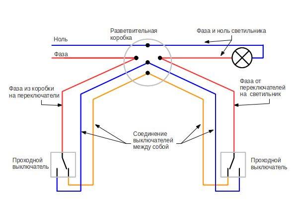
We provide electric potential through the phase wire L. It is used for the same purpose to control three groups of lamps.
Solution for three control points The organization of through-switching systems is largely determined by the area of the premises, the length, the number of door moves. We go up the illuminated stairs and turn off the light To illuminate the stairs, mid-flight switches are a necessity: control the lighting in the living room on the first floor; three lamps at the stairway; lighting control on the second floor area.
Four PVs are connected using cross switches as described above. Schemes with control from more than three locations The number of control locations is in principle unlimited.
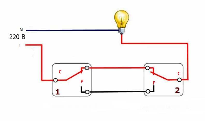
As mentioned above, in the absence of a circuit, it is better to call contacts at different key positions. The phase wire is fed to the inputs of both switches, and the other inputs of the switches are connected to one of the ends of one and the other lamp.
How to connect a two-gang through and cross switch from two or more places
See also: Snip power cable laying
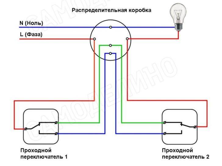
Lighting control scheme from 3 places
The scheme, in which there will be 3 or more switches per lighting fixture, is slightly different from the standard version. A simple three-wire marching switch will not help here. In the store you will need to purchase a toggle or cross switch, which is equipped with 4 outputs. It will act as an intermediate link between the main switches.
In the box, you need to find 2 secondary cores from the main switches and connect them to the changeover device. The wire from 1 of the main device goes to the input of the intermediate one, and the wire coming out of it goes to 2 to the output terminals. In order not to confuse anything, you should always refer to the diagram that is drawn on the devices themselves. It happens that the entrance and exit to them are located on the same side.


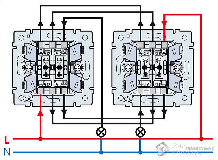
Only wires from a four-core cable are brought into the junction box, and the device itself is located in any place convenient for the user. With proper connection, the light will turn on and off from any installed device. Multiple toggle switches can be added to the circuit. The connection diagram of the main devices remains the same as with lighting from 2 places.
feed-through mounting and cross switches
The best option for electrical circuit design and installation
- at the stage of construction or at home during its capital
Need. repair to take into account all the premises in which you may need
independent switching on and off of lighting from 3 points
remote.These are long corridors, basement with several rooms
entrances and exits, flights of stairs. take into account Should and yard
buildings, street lighting.
who, Tem is going to mount the lighting on his own, but not
has skills, experts advise first to assemble a temporary scheme
lighting by connecting 2 walk-through switches with short wires and
connect a light bulb. It should be remembered which contacts were
wires are connected. After making sure the chain is assembled correctly,
switches need Sequence.
detach action
Installation of lighting is carried out in the following order:
- Lay and fasten the two-core connection wire for the feedthroughs.
switches. - At the installation site of the crossover switch, leave a small
loop, but the wire does not install. - cut the switches to their permanent place.
-
to the switches Connect the ends of the two-wire,
zero phase or wires.Wire connection
- Make sure the lighting can be independently controlled from 2
points. - circuit Disconnect from mains supply.
-
At the installation site of the crossover switch, a two-core cable
cut and install a switch in the cross gap.Break connection of two-wire Connect
- cable circuit to the mains.
- Make sure the lighting can be independently controlled from 3
points.
internal For work, any two-wire wire is suitable
insulated, the cross section of which corresponds to the intended For. load
For street lighting, a double-insulated wire is used.
Practice has shown that the control of long lighting
corridors, on flights of stairs, in basements cheaper rooms and
it is more practical to do with the use of walk-throughs and switches
cross.
Conclusions and useful video on the topic
How to install a single-gang surface switch:
The sequence of work when replacing the device:
Rules and sequence for connecting a two-gang switch:
Installing and connecting the switch is one of the simplest electrical work. Special knowledge and skills are practically not required here, but you should not treat this event irresponsibly either. Electricity does not forgive even the smallest mistakes.
Therefore, those who do not have experience in carrying out such work should seek help from specialists or more experienced home craftsmen.


