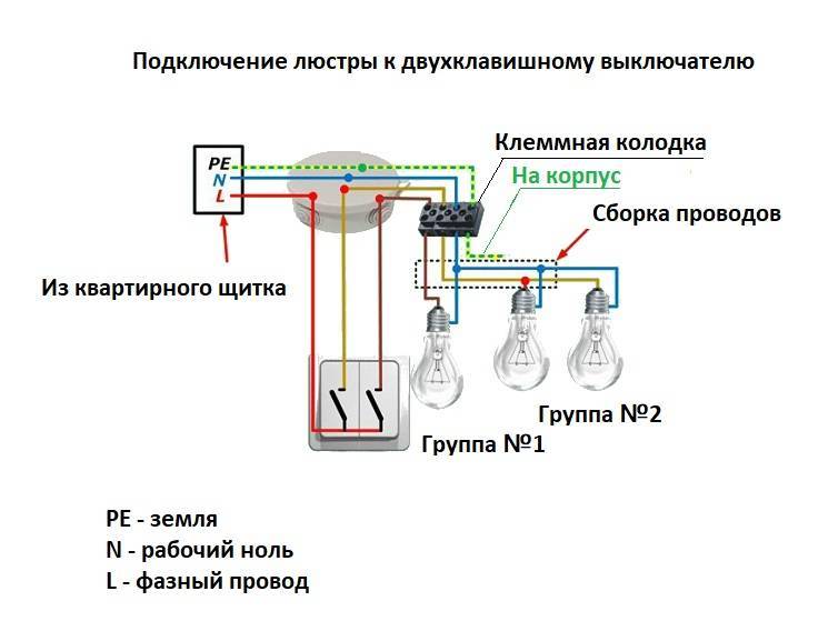
- How to connect a lamp to a two-gang type switch
- Types of two-gang switches
- Preparatory operations
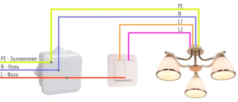
- grounding
- Phase and neutral conductors
- Connecting a Chinese chandelier
- The most common mistakes in connecting a chandelier
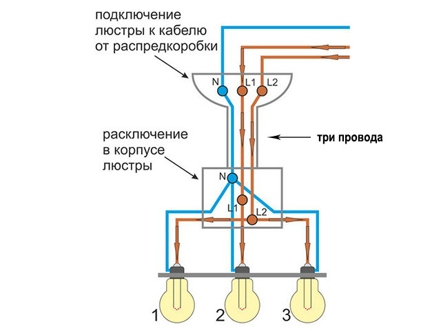
- If the number of wires in the chandelier and on the ceiling do not match
- Incorrect connection of the double switch
- Instead of a phase wire, a neutral wire passes through the switch
- Incorrect wiring diagram for the neutral wire of the chandelier
- The most common mistakes in connecting a chandelier
- Incorrect connection of the double switch
- Instead of a phase wire, a neutral wire passes through the switch
- Incorrect wiring diagram for the neutral wire of the chandelier
- Errors when connecting a two-gang switch
- Safety
- How to recognize wires?
- What threatens to swap the phase and zero?
- How to connect wires?
- Wiring diagram
- Installation and connection of the chandelier
- Preparation for work
How to connect a lamp to a two-gang type switch
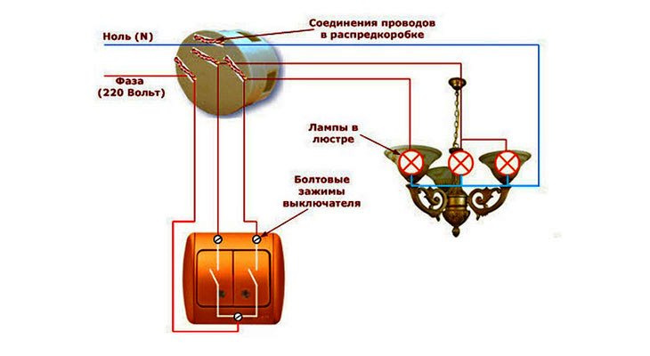
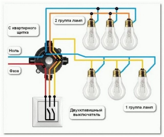
When connecting a chandelier to a single-key or two-key switch, it is important to understand its principle of operation. The lamp lights up due to the connection of several elements
At the moment the light source is connected, one conductor goes from the shield to the chandelier. The second is connected to the chandelier, but with a switch.It is important that using the switch it is impossible to carry out the zero view of the conductor. It must not have a break from the junction box.
Note! When determining the phase and neutral conductor, it is necessary to check where the voltage indicator is. This can be done in a storey form of a shield
You need to touch the element indicator with a measuring screwdriver. When the light comes on, this means that it is phase.

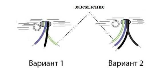
Several elements can go from the ceiling covering, one of which is a phase, and the other is zero. According to this wiring diagram, you can connect all the lamps. If three cables come out of it, then the first and next is the phase, and the third is zero. According to this scheme, you can distribute the connection of lamps in the chandelier. There is such a moment when three elements come out of the ceiling, but there is no way to distribute the inclusion of a chandelier. The third has a yellow-green color and is considered zero.

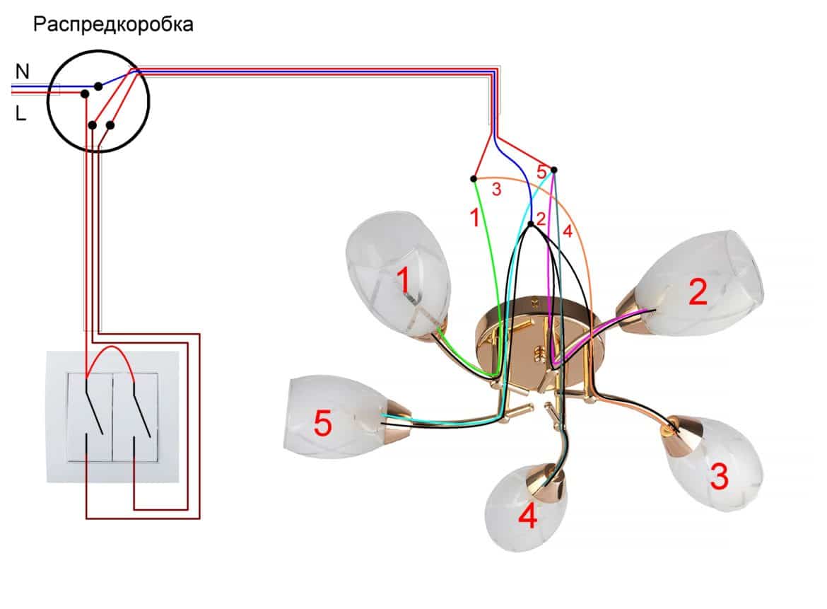
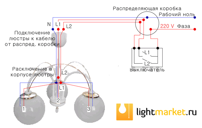
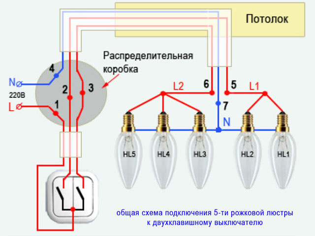
To connect the source to a switch that has two keys, you need to understand where the two, three wires of the chandelier or the five-arm switch are uncharged, and where the charged conductor is. To determine a common conductor, you do not need much knowledge, it has a different color from others. This means that the other two have several lighting sections. Then zero is connected to a common conductor, and each section, which has different phases of conductors, goes through a two-key type of switch.

Types of two-gang switches
Any two-button switch has three contacts. One above, two below.
The switch can be with or without backlit keys. In the first case, when using LED, energy-saving lamps, they can blink during operation or glow slightly when turned off.
Recently, LED lamps have appeared that are specifically designed for such switches. But their price due to a more complex electronic circuit is quite high. Cheaper to replace the switch.
If, with a limited budget, backlighting is vital, you will have to use one incandescent lamp of any power in the chandelier.
Preparatory operations
Such operations are connected with the fact that it is necessary to ring out all the wires for connection. This is especially true for those who do not deal with electricity all the time. As a rule, from 2 to 3 wires can stick out on the ceiling, and very rarely - four wires, but they are actually not needed, since even 2 wires are enough. If 3 wires still stick out, then one of them is grounding. If you know where the neutral wire is, where the phase wire is, and where the ground wire is, then there should be no problems connecting the chandelier.
grounding
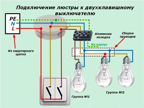
Grounding conductors are found in new buildings, as well as in apartments after major repairs, with the replacement of electrical wiring. As a rule, it is distinguished by a green-yellow color. It connects to the same conductor that is located on the chandelier, although not all chandeliers have a similar wire.
 The ground wire is in the houses of new construction or recently restored
It happens that there is no such conductor on the chandelier, so the ground wire on the ceiling is insulated and left unconnected, otherwise, if it is not insulated, it may accidentally touch the phase wire and then a short circuit will result, since the ground wire is always connected to the neutral wire.
Phase and neutral conductors
Working, the main conductors are considered "phase" and "zero".In old houses, all wires have the same color. In new homes or homes that have been refurbished, electrical wiring is done with multi-colored wires, which simplifies the wiring process. Unfortunately, this does not always happen and it is better to play it safe once again by ringing all the wires: there are all sorts of electricians and they do not always adhere to certain rules. This is especially true in relation to private specialists, who often do not even have documents allowing them to do such work.
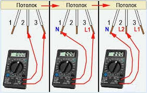
To determine which wire is which, you can use either a multimeter or an indicator screwdriver, with which it is easy to determine the phase conductor. If there are 3 wires on the ceiling, and they are switched by two switches, then there should be 2 phase wires and one zero. Switches should be turned on/off one by one to determine which phase conductor is associated with a particular switch key. After the purpose of all the wires is determined, you can start connecting the chandelier by turning off the machine on the light panel for reliability, although it is enough to turn the switch keys to the “off” position and check the presence of voltage on the phase wires using an indicator screwdriver. As a rule, phase conductors are switched by switches, as they are more dangerous.
 Continuity of wires on the ceiling with a temter
In the photo you can see by what technology the wires are determined in the presence of a multimeter. First of all, you should switch the switch on the multimeter to the position where the alternating voltage is measured, choosing the measurement limit greater than 220 V.When two phase wires ring, the multimeter will not show anything, so we can safely say that the third wire is zero. Then control measurements are made by connecting the third wire to the multimeter in turn and each of the wires defined in advance as phase. The device should show a voltage within 220 V. If the wires do not have different colors, then the neutral wire can be marked, for example, by sticking a piece of electrical tape.


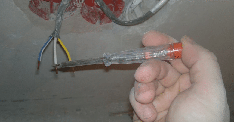
It is much easier to ring out all the wires with an indicator screwdriver: if the indicator lights up, then this is a phase wire, and if not, then zero. It remains only to mark them.
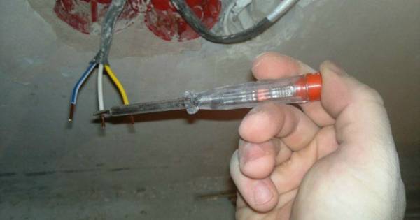 Using an indicator screwdriver to find the phase
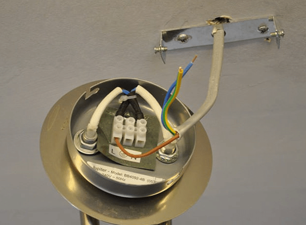
If 2 wires stick out on the ceiling, then these are “phase” and “zero”, although sometimes it is important to know which of the two conductors is phase. As a rule, on some modern chandeliers, “N” and “L” marks are placed on the terminal blocks, so it is advisable to connect the neutral wire to the “N” terminal, and the phase wire to the “L” terminal
Connecting a Chinese chandelier
Most of the relatively inexpensive chandeliers on the market come from China. What they are good for is a large assortment, but there are problems with the quality of the electrical assembly. Therefore, before connecting the chandelier, you need to check its electrical characteristics.
First check the integrity of the insulation. They can be assembled into one bundle and shorted to the body. The tester should not show anything. If there is any indication, you have two options: look for and replace the damaged wire or take it for an exchange.
The second stage of verification is the verification of each horn. There are two wires coming from the horn. They are soldered to two contacts in the cartridge.Each wire is called with the corresponding contact. The device should show a short circuit (short circuit or infinity sign, depending on the model).
After checking, start grouping the wires as described above.
The most common mistakes in connecting a chandelier
Errors during installation and connection are found not only among novice electricians, even among experienced professionals it often happens that the chandelier does not shine at all as it should. These errors are typical and commonplace.
If the number of wires in the chandelier and on the ceiling do not match
It may turn out that the chandelier you purchased has three wires, but wires on the ceiling where the chandelier is attached, there are only two, and the switch, respectively, is single. Or vice versa. The algorithm for connecting a three-arm chandelier to a single switch looks like this:
- Connect the neutral wire of the chandelier to the neutral wire on the ceiling.
- In the terminal block of the chandelier, install a jumper between the phase wires or clamp them in one terminal and connect them to the phase wire on the ceiling.
With such a connection scheme, it will no longer be possible to adjust the level of illumination.
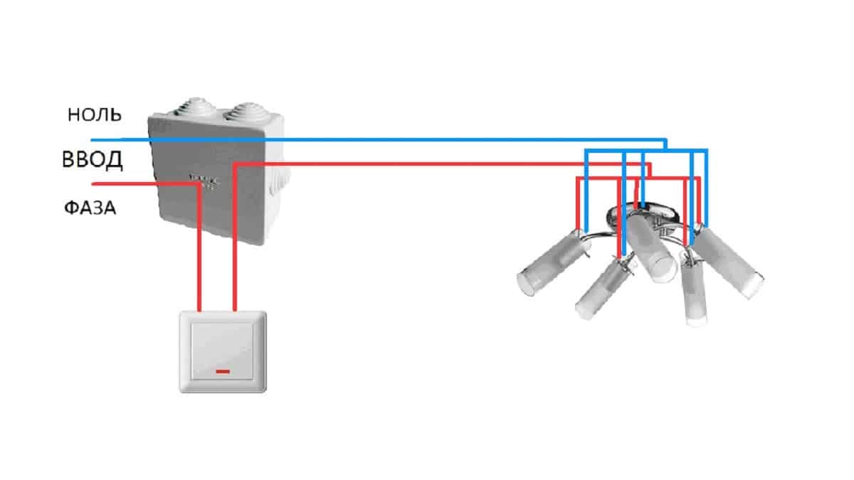
In the opposite situation, when there are three wires in the home wiring (two phase and one zero) and a double switch, and there are only two wires in the chandelier, the connection is made in the following sequence:
- Using a voltage indicator, you need to determine the neutral wire, connect it to any of the wires on the chandelier.
- Clamp the other two wires (phase) in one terminal, or put a jumper.
Incorrect connection of the double switch
This is the most common mistake in that the incoming phase wire is connected to one of the output contacts of the switch.With such a connection scheme, the chandelier cannot function normally, since one section of the lamps turns on only if voltage is applied to the other section.
That is, if the input phase is connected to the left contact of the switch, when the left button is pressed, the phase enters the junction box through the lower input contact and turns on one section of lamps. Pressing the right button again turns on another section. But when the left key is opened, all sections are disabled.
When the left key is released, it is impossible to turn on the right key.
The reason for the dependence of the right key on the left is that initially the phase went through the input contact of the switch of the left key, and the left key, when turned off, breaks the phase at once on both sections.
To eliminate this error, it is necessary to swap the connections of the incoming to the switch and the outgoing phase.
Instead of a phase wire, a neutral wire passes through the switch
According to the rules for the installation of electrical installations, a procedure is provided for connecting a switch that closes and opens the circuit by breaking the phase. How does it look on the diagram? The neutral wire, bypassing the switch, is laid from the junction box directly to the neutral wire of the ceiling lamp. The phase wire from the junction box passes through the switch key, which breaks the circuit.
However, in practice, sometimes there is an incorrect connection: not a phase wire, but a neutral wire passes through the switch. That is, when the switch key is turned off, the electrical wiring remains energized, despite the fact that the lighting is not on.This is fraught with the fact that electric shock is possible when replacing the lamp, if you accidentally touch the bare parts of the chandelier ceiling, or if the wire insulation is broken.
Therefore, if possible, it is desirable to eliminate such an error in the connection.
You can detect this violation of the wiring diagram using a voltage indicator, which, when the switch is in the “off” state, shows the presence of a phase on the ceiling wires.
Incorrect wiring diagram for the neutral wire of the chandelier
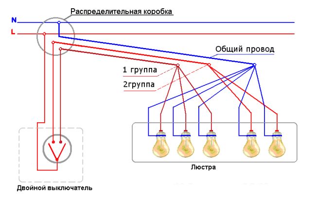
This error is the reason that only a part of the light bulbs normally turns on in the chandelier, the rest either shine weakly or do not turn on at all. As previously discussed, in the presence of three wires, the phase wires are each connected to a separate section of the light bulbs, while the neutral wire is common to all light bulbs, which are all connected in parallel to it.


If you confuse the wires, and the interconnected bulbs, for example, connect the first section to zero instead of the phase, and connect all the bulbs of both sections (instead of zero) to the phase, then when you press the first key in the first section, the bulbs will turn on, since they go there at the same time and zero and phase.
When you press the second key in the second section, the bulbs will not light, since both incoming wires will be phase, and in order for the bulb to shine, you need to apply a phase with zero to it at the same time.
The most common mistakes in connecting a chandelier
Errors during installation and connection are found not only among novice electricians, even among experienced professionals it often happens that the chandelier does not shine at all as it should. These errors are typical and commonplace.
Incorrect connection of the double switch
This is the most common mistake in that the incoming phase wire is connected to one of the output contacts of the switch. With such a connection scheme, the chandelier cannot function normally, since one section of the lamps turns on only if voltage is applied to the other section. That is, if the input phase is connected to the left contact of the switch, when the left button is pressed, the phase enters the junction box through the lower input contact and turns on one section of lamps. Pressing the right button again turns on another section. But when the left key is opened, all sections are disabled.

When the left key is released, it is impossible to turn on the right key.
The reason for the dependence of the right key on the left is that initially the phase went through the input contact of the switch of the left key, and the left key, when turned off, breaks the phase at once on both sections.
To eliminate this error, it is necessary to swap the connections of the incoming to the switch and the outgoing phase.
Instead of a phase wire, a neutral wire passes through the switch
According to the rules for the installation of electrical installations, a procedure is provided for connecting a switch that closes and opens the circuit by breaking the phase. How does it look on the diagram? The neutral wire, bypassing the switch, is laid from the junction box directly to the neutral wire of the ceiling lamp. The phase wire from the junction box passes through the switch key, which breaks the circuit.
However, in practice, sometimes there is an incorrect connection: not a phase wire, but a neutral wire passes through the switch.That is, when the switch key is turned off, the electrical wiring remains energized, despite the fact that the lighting is not on. This is fraught with the fact that electric shock is possible when replacing the lamp, if you accidentally touch the bare parts of the chandelier ceiling, or if the wire insulation is broken.
Therefore, if possible, it is desirable to eliminate such an error in the connection.
You can detect this violation of the wiring diagram using a voltage indicator, which, when the switch is in the “off” state, shows the presence of a phase on the ceiling wires.

Incorrect wiring diagram for the neutral wire of the chandelier
This error is the reason that only a part of the light bulbs normally turns on in the chandelier, the rest either shine weakly or do not turn on at all. As previously discussed, in the presence of three wires, the phase wires are each connected to a separate section of the light bulbs, while the neutral wire is common to all light bulbs, which are all connected in parallel to it. If you confuse the wires, and the interconnected bulbs, for example, connect the first section to zero instead of the phase, and connect all the bulbs of both sections (instead of zero) to the phase, then when you press the first key in the first section, the bulbs will turn on, since they go there at the same time and zero and phase. When you press the second key in the second section, the bulbs will not light, since both incoming wires will be phase, and in order for the bulb to shine, you need to apply a phase with zero to it at the same time.

Errors when connecting a two-gang switch
The first mistake that an illiterate specialist can make is to put on the switch not a phase, but zero.
Remember: the switch must always break the phase conductor, and in no case zero.
Otherwise, the phase will always be on duty on the base of the chandelier. And an elementary replacement of a light bulb can end very tragically.
By the way, there is one more nuance because of which even experienced electricians can rack their brains. For example, you wanted to check directly on the contacts of the chandelier - the phase comes there through a switch or zero. Turn off the two-keyboard, touch the contact on the chandelier with a Chinese sensitive indicator - and it glows! Although you have assembled the circuit correctly.
What can be wrong? And the reason lies in the backlight, which are increasingly equipped with switches.
A small current, even in the off state, still flows through the LED, applying potential to the contacts of the lamp.
By the way, this is one of the reasons for the blinking of LED lamps in the off state. How to deal with this can be found in the article "6 ways to solve the problem of flashing LED lamps." To avoid such an error, you need to use not a Chinese indicator, but a multimeter in voltage measurement mode.


If you moved into a new apartment where it was not you who connected the chandelier, and it behaves in such a strange way, that is, it does not react as it should to the two-key switches, then the point is most likely precisely in such an erroneous installation of the supply wires. Feel free to disassemble the switch and check the common contact.
If you have a backlit switch, an indirect sign of such an incorrect connection may be the failure of the neon light bulb. Why indirect? Since here everything depends on which key you will start the phase on.
The third common mistake is to connect the neutral wire on the chandelier not to the common zero in the junction box, but to one of the phase wires. To avoid this, use and observe the color coding of the wires, and even better, if you do not trust the colors, check the voltage supply using a high-quality indicator or multimeter before turning on the lamp.
Safety
Before you start connecting the chandelier to the mains, install the switch, you need to familiarize yourself with the safety precautions in working with electricity. To do this, you do not need to study the Talmuds of "physics on electricity", you should familiarize yourself with the rules:
- In all used tools for working with electrical appliances, as well as for electrical wiring, the handles are insulated.
- To carry out work, the electricity in the entire room is turned off on the panel. To do this, turn off the light switch is not enough. It is required to turn off the plugs on the electrical panel (meter in a private house), but if there are no buttons there, the plugs are unscrewed.
- The switch for the lamp is installed in the break of the "phase" wire.
If you follow these rules, then nothing will threaten life.
How to recognize wires?
All wires are available in several colors. This greatly facilitates the work of an electrician, and gives a hint to a beginner.
Common Standard:
Grounding - yellow wire with a light green stripe (ground).
- Blue (blue) wire - zero.
- Phase colors are colors other than those listed.
In houses and apartments with old wiring, all cables are the same, there was no grounding. To determine the type, you should make a call.
What threatens to swap the phase and zero?
There is an opinion from people who consider themselves professionals (I installed 1 socket in the house) that when installing the switch, there is no difference in connecting the wires, because electricity does not enter the lamp through open contacts. This is not true. You should know exactly what is the phase, and which wire goes "zero". With a broken zero, no electric current flows, but there is a phase current in all cables. What threatens to defeat a person with electric current. Otherwise, fluorescent lighting fixtures, as well as economy lamps, flicker or dimly shine with phase current.
How to connect wires?
Twisting is a very laborious business. If it is done incorrectly, a remake is made. Therefore, you should do it correctly, as well as firmly isolate it. If there are a lot of such twists, and there is a lot of voltage in the network or poor contact of the connection is heated, then the electrical tape may burn out soon, which will lead to a short circuit. Therefore, when twisting the wires, it is necessary to press them well and isolate them.
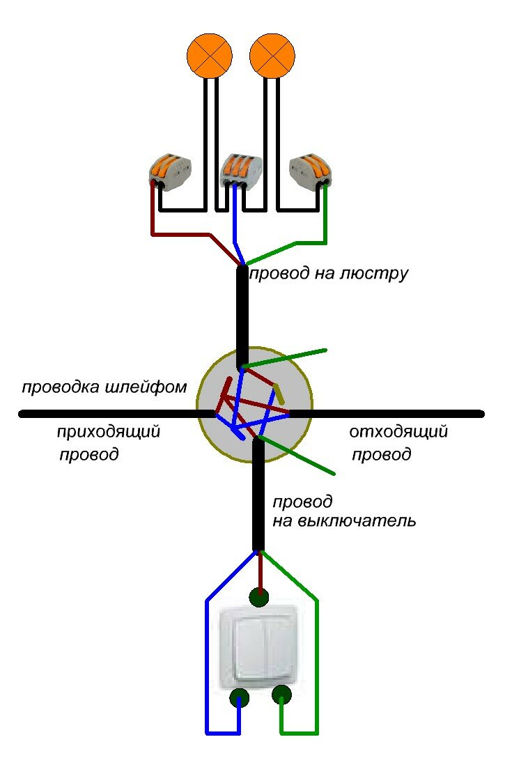
Terminal blocks are now used. They have proven themselves as fire-fighting elements. With their help, four or more twists are connected. One of them is WAGO. No tools are required for connection, installation takes place in a short time. To begin with, the levers open, insert the wires there and close the lever. In this case, the connection will be reliable, fireproof. The purchased new chandelier is disassembled, the quality of the blocks and screws is checked. If necessary, the screws must be well tightened. Especially if the chandelier is made in China.
Wiring diagram
We connect as is. You just need to follow the instructions clearly and take your time.
Since here everything depends on which key you will start the phase on. You should have 4 free unconnected wires left.
The same is with the phases, but they are connected from the switch to the phase wire. If protective grounding is present, then one end of the conductor is connected to the body of the chandelier, and the other to the ceiling protective conductor.
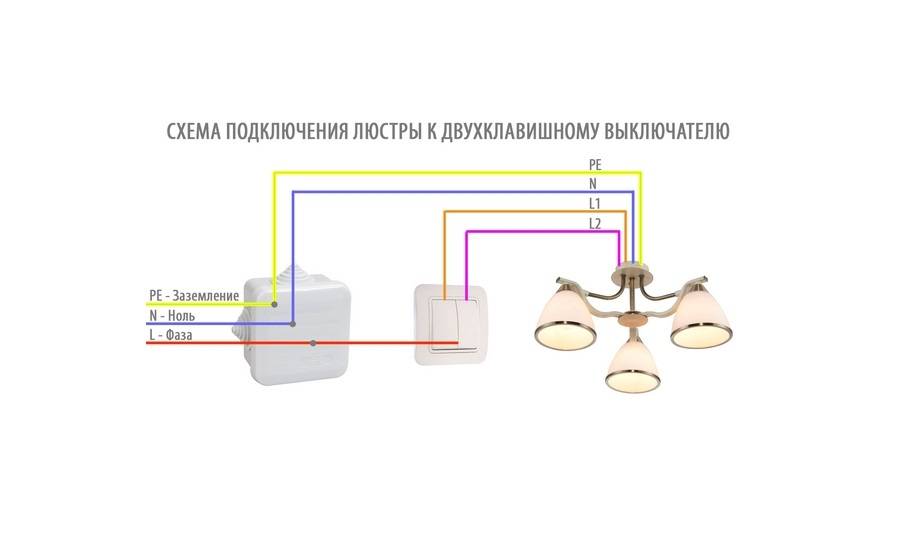
If necessary, they must be carefully separated in different directions, after turning off the shield. First of all, you need to deal with the wiring on the ceiling, which in the standard situation has three wires: L1 - the phase of the first switch key; L2 - phase of the second key; N is zero. Depending on the modification, it can be surface-mounted or built-in, easily mounted on the outer or inner part of the wall. How to connect a chandelier?
In this article, we will deal with the design and consider the circuit connecting a two-gang switch. Only 2 electrical wires connected to the ceiling contacts are free.
When the chandelier has more than one lamp, there are no problems with its connection. The right side of the figure shows the electrical circuit of a five-arm chandelier, in which all the lamps are connected in parallel. If protective grounding is present, then one end of the conductor is connected to the body of the chandelier, and the other to the ceiling protective conductor. The number of circuits is determined by attaching 1 tester probe to the phase, and alternately touching the middle phase contact of the remaining cartridges with 2 probes.


Safety precautions when installing chandeliers with connection to switches Those who are going to independently connect the chandelier to any of the above switches using any of the methods described above should once again be reminded that installation work on the installation of lamps and high-quality connection of switches must be carried out in compliance with safety regulations. The zero core should immediately go to the ceiling. And the other two are phase, passing through different switch keys. By including these groups in one or another combination, you can get 3 gradations of brightness: Lamps do not burn.
If the wiring has the same color, it is better to mark it with markers. From each junction, a brown and blue dot leads to its ceiling wire: brown to phase, and blue to zero.
How to connect a chandelier with your own hands. Connection diagram.
Installation and connection of the chandelier
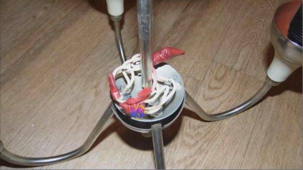
Here is our chandelier:
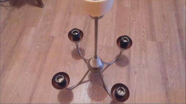
To begin with, we remove all the shades and check the cartridges for defects.
When we check all four cartridges, we move on to wiring.
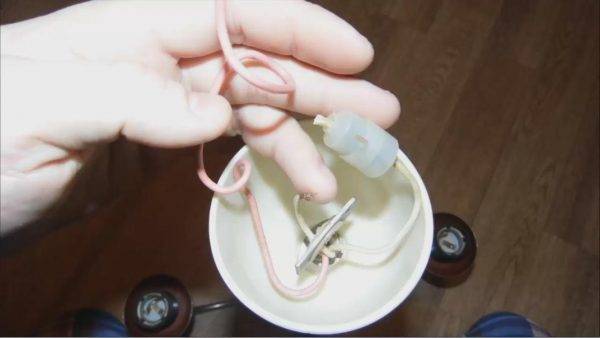
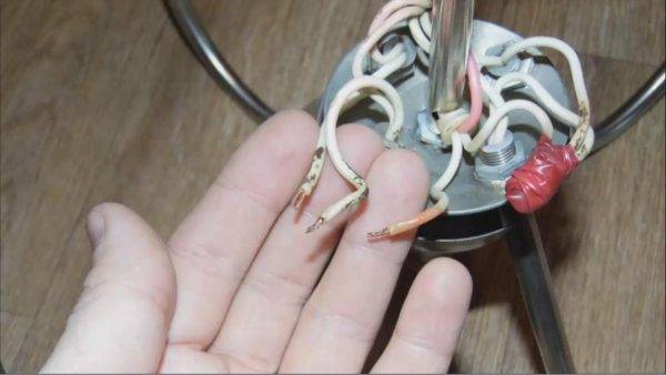
As you can see, there are two white wires and one pink. We have two wires going to the phase and one wire, pink in this case, goes to “zero”. This is a common wire that goes one to all four light bulbs. Let's still make sure that these are the phase wires and “zero”. To do this, you have to disassemble the chandelier.
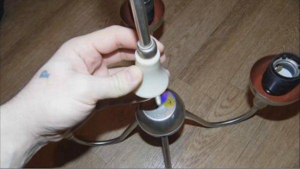
The chandelier is disassembled quite simply - everything in it just rises. The parts here are sealed, so they hold tight.

We take it all up piece by piece. What do we see here?
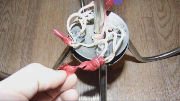
We see a bunch of wires twisted with electrical tape, but so far we can’t really make out anything.
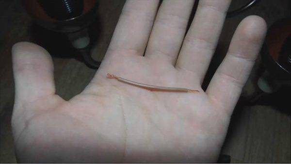
This is where the pink wire comes out, and there are already four wires coming out of it in a bundle.This suggests that it goes to all four bulbs. Two wires go separately, each for two light bulbs. Two wires come out of each twist. So, we made sure that the pink wire is “zero”, and the two white wires are the phase. Here, as you can see, the tape has not been rewound for a long time, it is twisted very badly, so we will change it.
Here's the usual twist:
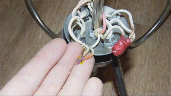
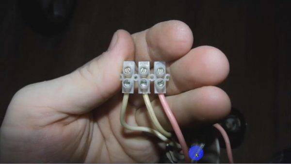
We'll put clamps on it. We untwisted everything, trimmed it and put the following terminals:
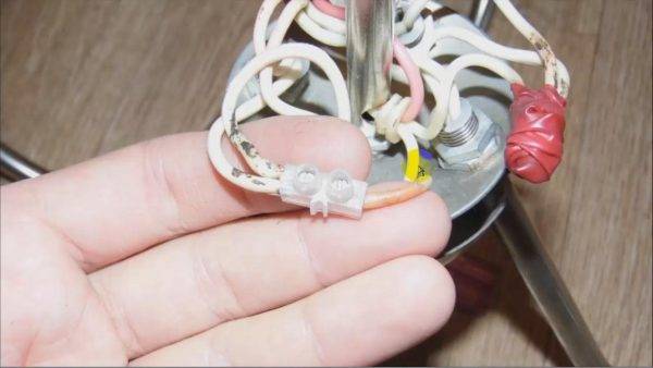
The phase wire goes to two light bulbs. You will also need to connect a second wire, which also goes to the phase. For "zero" we need one more piece of wire:


What is it for? Since the terminals were only of narrow diameter, all the wires did not fit there. We have one neutral wire going to one bulb, and for the second we made a jumper to the next terminal, from which the same wire goes to the remaining two bulbs.
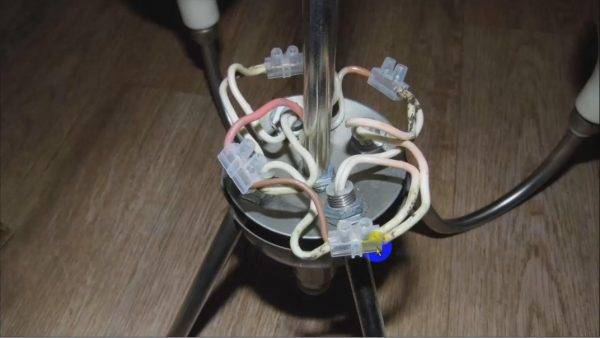
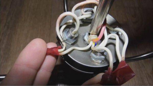
Then we assemble this chandelier again, also very simply and quickly, we deal with the wires that we saw before and make the connection itself.
These three wires are again “zero” and two phases. We also connected them to the terminal. Let's move on to the installation itself.
Preparation for work
First, it is necessary to determine the phase, zero and ground among the wires, the presence of which is optional. For ease of detection, you can use the electrical circuit in the passport document for the chandelier, indicating the purpose of its conductors and the stages of their connection.
Standard color code:
- White or brown conductor - phase;
- Blue - zero;
- Yellow-green - grounding.
The connection is made to the wire of the same color on the chandelier.In its absence, the bare wire is carefully insulated so as not to accidentally short it out.
Before starting work, the switch keys should be switched to the “off” position. The input machine on the panel must also be in the off state. Preparing the wires for testing is to open them. The luminaire is connected with the power off. After the preparatory work, power is supplied to the wires.
Step-by-step instructions for ringing wires with a tester:
- The luminaire is connected with the power off
The device is set to the dialing mode, and the probes should be short-circuited for a short time. A characteristic sound will indicate the correct choice of the measurement limit and the health of the device.
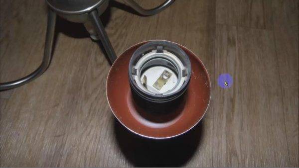
- After unscrewing the lamps, 2 contacts are determined in their cartridges: the central one is the phase, and zero is on the side, which comes into contact with the base when the bulb is screwed in.
- To find zero 1, the tester probe is installed on the side contact of a cartridge, and 2 in turn touch the outgoing stripped wires. If touching 1 of them is accompanied by sound, the neutral conductor is found.
- To search for phase 1, the tester probe is installed on the middle contact of a cartridge, and 2 touch other wires. Phase detection is accompanied by sound.
- The number of circuits is determined by attaching 1 tester probe to the phase, and alternately touching the middle phase contact of the remaining cartridges with 2 probes. If the chandelier has 1 contour, the sound will accompany any touch to the cartridges. If a part of the cartridges is not connected to the circuit, a check is made for the 2nd circuit, for which the probes touch the middle contacts of the cartridges and the 3rd wire.The sound will confirm the double-circuit chandelier, and the 2nd wire is the phase.
- In the presence of 1 circuit 3 wire - grounding. For this check, 1 probe touches the metal housing parts, and 2 probe touches the 3rd wire. The accompanying sound will serve as proof.


