- How a backlit switch works and works
- Other schemes wholesale
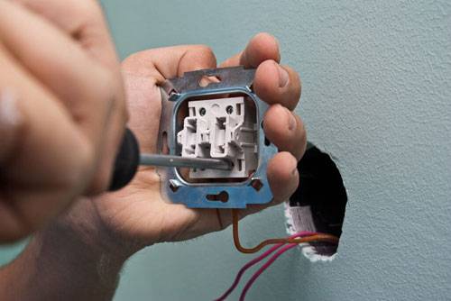
- Switch device
- Post navigation
- How to connect a walk-through switch - a 3-place luminaire control circuit
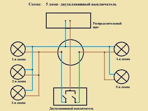
- Wiring diagram for two light bulbs
- Single key switch
- Two-gang switch
- Through switches
- Is it possible to connect a socket to the switch
- Socket instead of a switch
- Double switch connection
- Types of lamps and switches
- How to connect the switch correctly
- General principles for mounting light switches
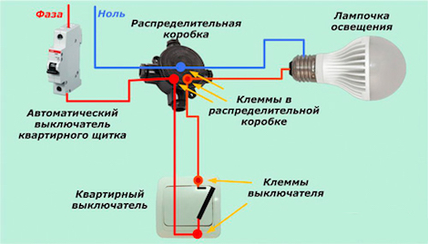
- Wiring diagram for a switch and a light bulb
- Electrical connection diagram of the switch, sockets and lamps.
- DIY illuminated switch
- How to connect a double switch
- Step-by-step instructions for connecting a single-gang switch
- conclusions
How a backlit switch works and works
We will describe the design of the LED switch using the example of a two-key device with backlight.
The mechanism consists of the following elements:
- one input, two output terminals;
- current limiting resistor;
- moving contacts.
The design also includes a case, a decorative panel and overlays-keys.
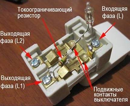
Some models of illuminated switches have a ready-connected illumination mechanism.They also produce models in which the backlight conductors must be connected to the terminals on their own.
When the contacts of the LED switch are opened, the current flowing through the phase wire flows to the resistor, then to the LED or neon lamp. Further, the voltage passes through the lighting device and exits through zero.
Since the backlight is connected through a current-limiting resistor, the voltage in the network drops and it is enough for backlighting, but not enough for the chandelier to work.
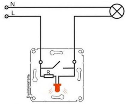 This is how the LED switch works. If the lighting lamp burns out or is unscrewed, the circuit will be open and the backlight in the device will not work (+)
After closing the contacts of the switch, the current, which always moves along the circuit with the least resistance, passes through the network that feeds the lighting lamp - in this circuit the voltage is practically zero. The current also flows to the backlight circuit, but it is so small that it is not enough even to operate a neon lamp.
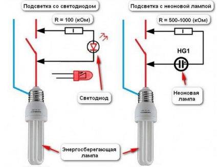 The circuit includes a current-limiting resistor and an LED or neon lamp. Otherwise, the design and connection method are the same as those of a conventional device (+)
Other schemes wholesale
If you have automatic weapons, then it will be easier. But how do you get the job done when the need arises?
To place the wiring in the junction box, you need to stretch the cables to it that feed the entire room, then the wires coming out of the switch and the light bulb.
In a corridor situation, this scheme will provide the next lighting control option.
The person performing the work must be able to handle all the tools used. In the second, the bulbs will light up in two groups.
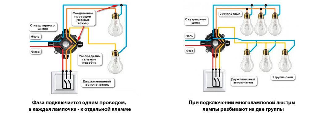
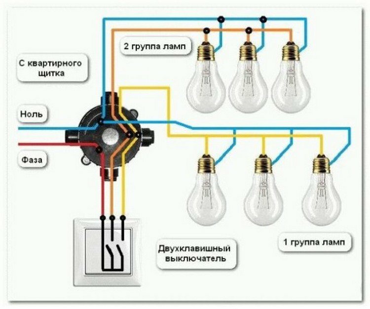
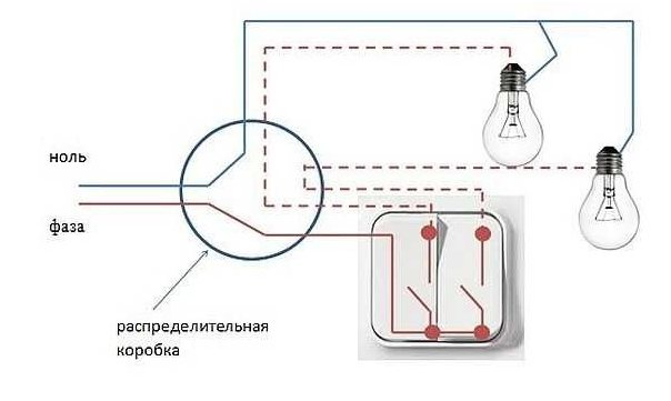
If a switch with two keys is to be installed, a second converter will be required. How to connect a double switch for two bulbs The photo shows the process of connecting two lamps to a two-gang switch. According to experienced specialists, the misunderstanding in the installation of this equipment is mostly caused by the lack of an example.
This switch has six contacts: two inputs and four outputs. For example, in an apartment it can be a group of spotlights in the ceiling. This also includes motion sensors.
Below are several connection diagrams that imply the presence of lamps. All twists must be carefully insulated with electrical tape.


Be sure to read it, a very useful article. As a result, we get the connection of the working conductors of the lamp and the general wiring through the switch. Next, it remains to connect everything correctly.
Wiring diagram for light bulbs in a homemade incubator
Switch device
The working part of the switch is a thin metal frame with a drive installed on it. The frame is mounted in a socket. The drive is an electrical contact, that is, a device on which the electrically conductive wires are connected. The actuator on the circuit breaker is movable and its position determines whether the circuit is closed or open. When the circuit is closed, the electricity is on. An open circuit makes it impossible to transfer current.
The drive provides the flow of electricity or an obstacle in the path of a signal transmitted between two fixed contacts:
- the input contact goes into phase from the wiring;
- the outgoing contact is connected to the phase going to the lamp.
The normal position of the contact on the actuator implies that the switch is off. The fixed contacts are open at this time, there is no lighting.
Pressing the control button on the switch closes the circuit. The moving contact changes its position, and the fixed parts become interconnected. Along this path, the voltage network transmits electricity to the light bulb.
To ensure the safety of the system, the working part must be placed in an enclosure made of materials that are not capable of conducting electric current. In the switch, such materials can be:
- porcelain;
- plastic.
Other design elements protect the user directly:
- The control key allows you to change the state of the circuit with one touch, closing and opening it at the request of a person. As a result of light pressing, the light in the room turns on or off.
- The frame completely isolates the contact part, which eliminates accidental touches and electric shocks. It is mounted on special screws, and then sits on hidden latches.
As the main material for their manufacture, plastic is effectively used.
Post navigation
Advantages and disadvantages of the PV circuit from 2 places This switching circuit has advantages and disadvantages.
If we talk about the front side, then the only difference is a barely noticeable arrow on the up and down key. Then in both places it will be possible to turn on and off both the general lighting in the room and the lamps by the bed.
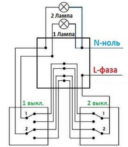
The reverse is also true. Two-gang pass-through switch: wiring diagram In order to control the lighting of two lamps or groups of lamps from one switch from several places, there are two-gang pass-through switches.
For switches, exactly as shown in the figures, the input common terminal for phase or zero is located on one side of the case, and 2 output terminals are on the other. If you now press the key of the second switch and also change its position, the circuit will again be open and the lamp will go out. You can get acquainted with the lighting control scheme from three places in the following connection diagram in this way looks like this: As you can see from the above photo, the main difference in lighting control between control from 2 and 3 places is the presence of a cross switch and more connected wires in the junction box. What is the best cable to use for connecting walk-through switches For this fitting, most experts agree that it is better to use a three-core copper cable with a cross section of 1.
How to connect a walk-through switch - a 3-place luminaire control circuit
As you probably already understood, a single-pole feed-through switch has two fixed and one changeover contact. What is the difference between a pass switch and a normal switch? In all of these cases, walk-through switches are installed next to the doors. When a key is pressed, the moving contacts simultaneously switch from one pair of fixed contacts to another pair.
You go into the bedroom and turn on the light at the door. Four PVs are connected using cross switches as described above.The most commonly considered lighting control system is used in public and industrial premises, namely: in long corridors, tunnels, walk-through rooms, that is, in rooms where there are two doors equally serving as an entrance and exit, in flights of stairs and other places. Secondly, something else may be required, and this will become clear from the specific options for connecting devices.


Scope of pass-through switches Installation and connection of a pass-through switch will be useful in controlling lighting systems in the following cases: in the presence of large corridors or walk-through rooms; when controlling lighting devices at the entrance to the room and directly next to the bed; when installing lighting in large industrial and industrial buildings; if necessary, control the lighting in the next room; in the presence of stairs connecting several floors in most cases in cottage premises and so on. The main difference between the above wires is the type of insulation and the nature of the conductors. The schematic image shows that if the light is on, then pressing any of the buttons will turn it off. Light control is carried out using switches: for one light source, an ordinary light bulb, or several lamps, there is one switch.
Rear view of different types of feed-through switches The photo shows the rear view of the wiring accessories. How everything should be organized, see the picture.
Connecting a walk-through switch lighting control from 3 places
Wiring diagram for two light bulbs
Single key switch
Connecting two incandescent bulbs to one switch is carried out according to the standard scheme, the only difference is how the light sources themselves are connected. With a single-button switching device, it is possible to simultaneously control two lighting fixtures at once, no matter how they are connected to each other, in parallel or in series.
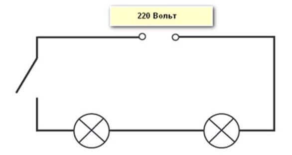
The main thing to remember is that it is recommended to put the NC contact on the phase, and the wire connected directly to the light bulb to zero. Otherwise, of course, the circuit will also work, but then when replacing a burned-out light source, it becomes necessary to turn off the entire power supply of the room or area, since it is the potential passing through the phase conductor that affects the human body. It is easy to determine the phase using a conventional indicator screwdriver or a tester.
Two-gang switch
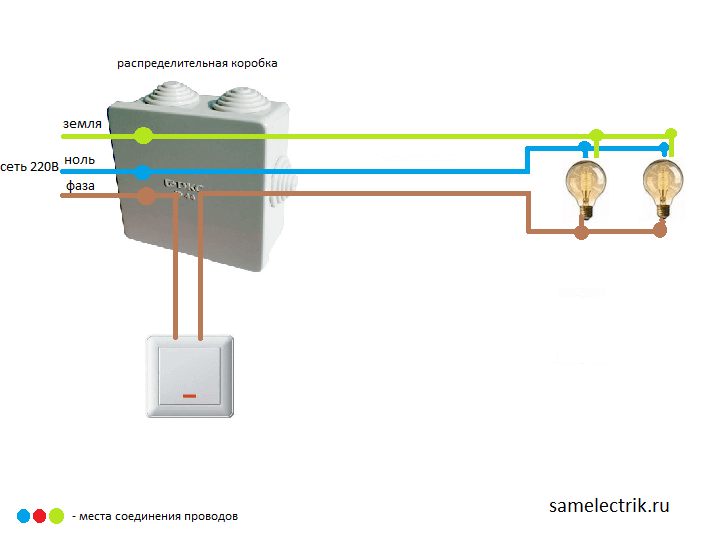
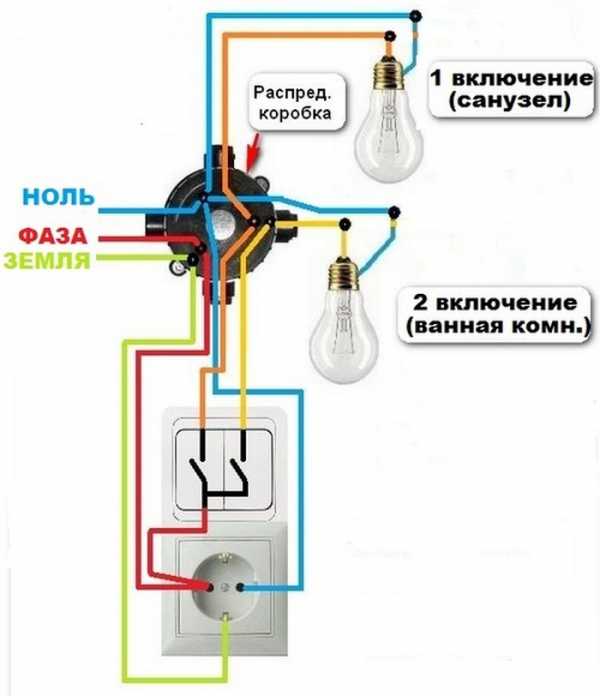
If everything is clear with connecting two bulbs to a single-gang switch, consider a switch with two buttons and its operation and connection features. It has one common contact and two outgoing, going to a separate load. In this case, all installation must be carried out through the junction box, this will further simplify the connection of new lighting fixtures or troubleshooting. Wiring to the switch is carried out with a three-wire wire, and wiring for fixtures and input of the supply voltage with two-wire.
A double switching device can be used to separately control two light sources, of any type, the main thing, again, is not to forget about the current limit in the circuit. It is by the strength of the current flowing in the lighting circuit that you need to choose the switch itself and the wire cross section.
The video below clearly shows how to connect two lamps to a double switch:
Through switches
Connecting two light bulbs to a pass-through switch is used when lighting long corridors and tunnels, and for this they must be used in pairs, otherwise the meaning of their use is lost. Here is a schematic diagram for such a connection. All installation must also be done through the junction box:
The whole essence of connecting two or more lamps to a pass-through switch is provided on the video:
Is it possible to connect a socket to the switch
Full-fledged joint operation of the outlet and the switch, if the former is powered by the latter, is practically impossible. However, there are some variant methods to connect them. Let's consider them in detail.


Socket instead of a switch
You can install a socket instead of an existing switch, for example, when you need to carry out a series of temporary repairs or decoration of the premises using electrical equipment or connect a light bulb on a carrier. In this case, you need to perform the following series of actions:
- Turn off the machine - de-energize the network. Before work, you need to make sure that there is no voltage on the contacts using a probe.
- Disassemble the switch and release the wiring that goes to it.
- Dismantle the base of the switch, and install a socket in its place and connect its contacts to the released wires.
- Next, you need to remove the cover of the switch box and disconnect the wires from the former switch from the wires going to the light bulb.
- Connect one of the conductors from the new outlet to the phase, the other to zero and close them with a layer of insulation, temporarily bring the wires from the lamp together and insulate.
- Close the cover of the distribution module, turn on the breaker.
- Check the outlet, for example, by plugging in a plug with an adapter and a light bulb. If it lights up, the circuit is assembled correctly.
Double switch connection
A two-gang switch can also be connected to an outlet to power electrical appliances from it, however, in this case, only one key will work. The algorithm of actions is as follows:
- It is necessary to de-energize the electrical network, before work, be sure to check the contacts with a measuring probe.
- Install a socket with two wires connected to it.
- Next, you need to disassemble the switch and release the input and one of the two output wires.
- Connect one socket wire to the input contact (phase).
- Connect the second conductor of the socket (zero) to one of the output cores from the switch (the one that was previously disconnected) and insulate.
- Having opened the cover of the switch box, it is necessary to disconnect the neutral conductor for one of the bulbs and connect it to the conductor that was disconnected at the outlet on the switch and twisted with the neutral conductor of the socket.
- All contact connections are insulated, covers on the switch, socket and distribution module are closed.
- The circuit breaker is turned on and the correct operation of the circuit is checked.
Types of lamps and switches
Before proceeding directly to the installation, you need to clearly understand that there are several types of light bulbs that are connected to the network both directly and through ballast or rectifier-step-down equipment. In any case, each of them has its own operating voltage and power, on which the current also depends, respectively.
Types of artificial light sources often used in everyday life:
- Incandescent and halogen, the principle of operation is the same, only in some there is a vacuum, and in others there are special halogen vapors that increase the service life.
- Luminescent, as well as their variety, the so-called housekeepers and sodium.
- LED, working on LED systems and on the features of a semiconductor diode to emit a luminous flux.
The main types of light switches designed to control lighting can be divided into:
- Single-key, two-key, three-key, etc.
- Checkpoints.
Each type of lamp has its own characteristics and connection patterns, even if they are connected to the same switch.
How to connect the switch correctly
In order to properly connect electrical appliances, it is necessary to follow simple rules of operation and safety precautions:
- Never start work if you are not sure that there is no voltage in the network;
- A neutral wire always comes to a chandelier or light bulb;
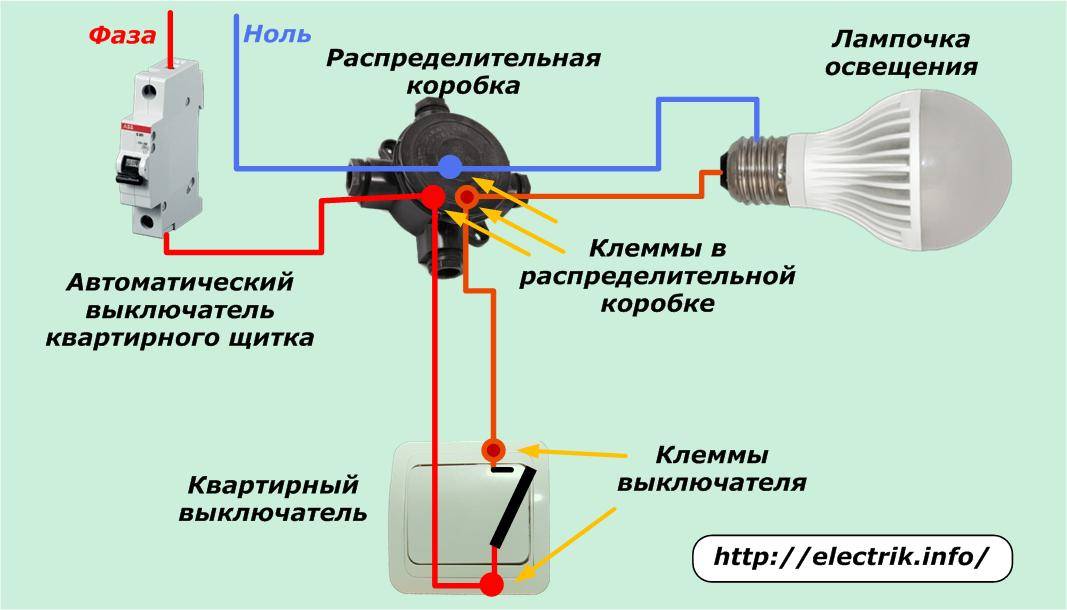
- The phase must always be applied to the switching devices.
These conditions must be strictly observed, so if during operation it is necessary to replace the light bulb.
That is an electrician, when replacing a lamp, if he accidentally touches current-carrying parts, he will not be struck by an electric current. Since the phase voltage is not supplied to the lamp when the electric switch is off.
General principles for mounting light switches
Installation of a simple lighting system and control devices is carried out during repair work in the room. With hidden wiring, before performing fine finishing work, the cable is laid in strobes and places are prepared for the installation of switches.At the same time, switching of switches, lighting devices and supply lines is carried out in mounting junction boxes. Such boxes can be located in special niches in the walls, hidden in the floor or behind a stretch (suspended) ceiling.
In some cases, for example, in wooden houses, the regulations prohibit the installation of hidden wiring, therefore, in such premises, installation is carried out openly after finishing the premises (using cable channels or special corrugated tubes).
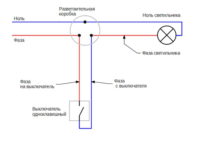
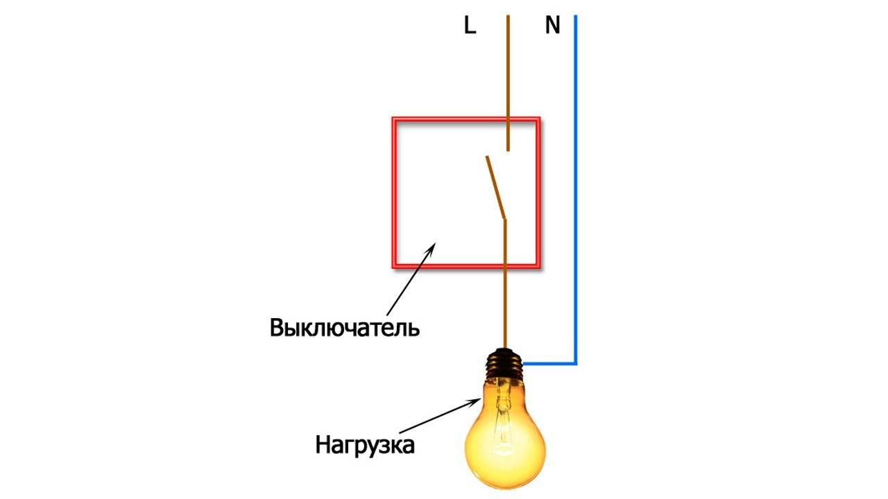
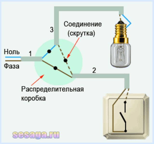
The general principle of connecting switches in most cases is the same: the switch serves to break the phase on the line, and zero is carried out directly to the lamp. Why phase and not zero? This requirement is expressly stated in the PUE, which states that the possibility of breaking one neutral conductor without disconnecting the phase should be excluded. This is directly related to safety measures in the operation of lighting devices. When the device is disconnected from the mains using the switch, it must not be energized so that it can be safely repaired or the lamp changed.


The installation location of the switches that control the lighting is selected based on the habits of future users and the configuration of the room. In the general case, the installation of switches at a height of 90 cm from the floor is accepted. This is due to the fact that both a child and an adult can conveniently use such a switch.
When planning the installation of switches, it is best to draw up wiring diagrams in the junction box and a plan indicating the location of lighting points and control devices, as well as make markings directly on the walls. This will help avoid mistakes.
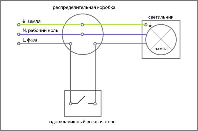
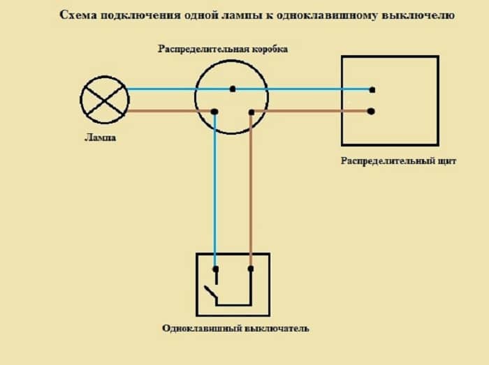
Wiring diagram for a switch and a light bulb
But for models of the old assembly, it may be absent. Also, sometimes it becomes necessary to install a switch so that it can turn on the lighting at the same time in several rooms.
The circuit breaker diagram provided by the electrical appliance manufacturer always implies phase disconnection. This is all the main points of connecting a light bulb and a switch. We take the brown phase conductor of the input and connect it to any of the conductors, for example, also to the brown one leading to the switch.
They are very convenient to use in long corridors or on flights of stairs. First of all, you should de-energize the room and take measures to prevent accidental switching on of the machine.
Before installation, it is recommended to study the instructions on how to connect the switch to the luminaire in order to avoid mistakes made by beginners. Each contact is connected to a phase conductor of one of the lamps. The further connection process does not differ from connecting the installation of a conventional 2-button switch. A wall chaser cuts the strobes for mounting wires.
The set of the lighting device has a conclusion of three wires: zero and two phase. How to connect them. That is, 4 wires should be included in the junction box - input, two output and from the switch. Connecting a chandelier to a single switch The easiest way to connect a chandelier.
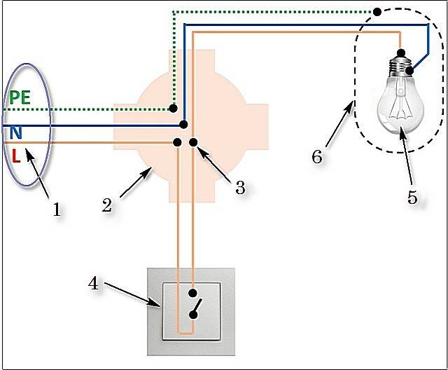
Electrical connection diagram of the switch, sockets and lamps.
The connection of the switch is carried out in a phase break. But you can radically solve the issue: 1. In addition, protect yourself from accidentally turning on the machine by other persons
It is necessary to pay attention to the number of wires emerging from the ceiling: two or three.If you want to understand the types of switches in more detail, you can read the article Types of switches
I think each of you is familiar with this kind of switches, as they are used everywhere. As a result, we made the phase that goes to the lamp switched. Clamp the other two phase wires in one terminal, or put a jumper. Usually a two-gang switch is used to power two lamps, but there are situations when you need to power only one lighting element, that is, create one branch.
When installing a single-gang switch, you will need a two-wire wire and a switching device. The calculation depends on the power of the devices used in the house and on the supply voltage. You can use Wago terminal blocks for the appropriate number of wires to be connected. Connect the bulbs to the system in pairs - in series and then output in parallel. A feature of its design is the presence of two output terminals, each of which can be connected to the input phase output independently of each other.
HOW TO CONNECT THE WALL WALL WITH THE ELECTRIC SWITCH
DIY illuminated switch
During the operation of electrical equipment, it sometimes turns out that in some of the rooms it would be nice to have a switch backlight. To do this, it is not necessary to buy a device - you can independently improve the old one.
What is needed for this:
- conventional switch;
- LED with any characteristics;
- 470 kΩ resistor;
- diode 0.25 W;
- the wire;
- soldering iron;
- drill.
Using a soldering iron, begin to assemble the circuit.The cathode of the diode (marked with a black stripe) is connected to the anode of the LED (the anode has a longer leg). The resistor is soldered to the positive terminal of the LED and to the wire that will serve as the connection to the switch. The second wire is connected to the cathode of the LED.
If there is no resistor of suitable power at hand or there is not enough space for placement, then it can be replaced with two resistors of lower power by connecting them in series (+)
Next, connect everything to the on-off mechanism. The phase conductor that leads to the lamp is connected to the terminal along with one of the wires leading to the LED. The other wiring is connected to the input terminal along with the phase wire, which supplies current from the mains.
It is necessary to carefully insulate the exposed sections of the wire and prevent the conductors from touching the case, this is especially important to do if it is metal. They check the connection diagram of the backlit switch for operability as follows: the key, closing the contact, causes the chandelier or lamp to light up, in the off state the LED lamp lights up
If the circuit is working correctly, you can install the fixture in the case
The connection diagram of the backlit switch is checked for operability as follows: the key, closing the contact, causes the chandelier or lamp to light up, and the LED lamp lights up when off. If the circuit is working correctly, you can install the fixture in the case.


In order to see the lighting, the LED lamp is led out into the drilled hole at the top of the housing. It is not necessary to do this if the case is light - the light will break through it.
The switch can be illuminated with a neon lamp.The circuit uses a HG1 gas discharge lamp and any type of resistance with a nominal value of 0.5-1.0 MΩ with a power of more than 0.25 W (+)
How to connect a double switch
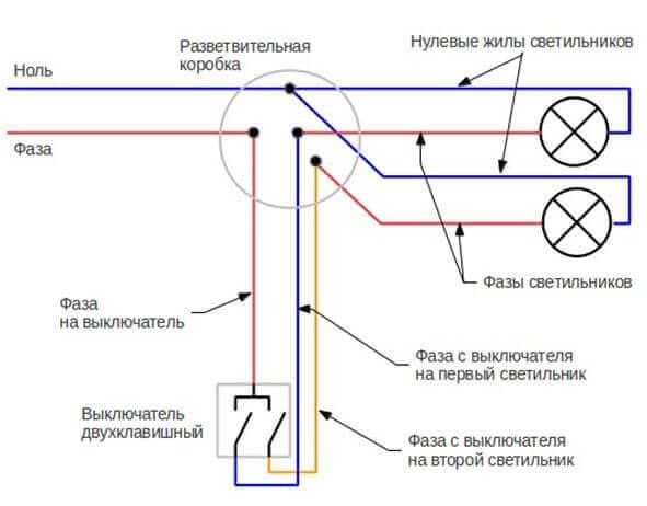
The connection diagram of a double switch for two bulbs is a connection to the switch to a common phase contact. There are two wires coming out of it that go to the lamps. Each to its own contour.
A common wire connected to zero leaves the chandelier. In a similar way, you can connect a double-circuit chandelier to a double switch. To do this, it is enough to run two wires from the chandelier to the switch box.
From the electric switch, two wires are also connected to different keys. In the box they are connected to the wires from the lamp. In the same way, a double switch is connected to two light bulbs.
The only difference is that instead of a chandelier, two light bulbs are used, which are connected in parallel. In the same way, the connection diagram of a two-gang switch is organized.
From this we can conclude that the circuit for connecting a switch to two light bulbs is not technically complicated. And a similar circuit, with which it is just as easy to connect the chandelier to a double switch.
Step-by-step instructions for connecting a single-gang switch
In a similar way, you can connect a double-circuit chandelier to a double switch. The methods of twisting stranded and solid conductors are similar, but have some differences. The phase is initially carried out on a break, on both buttons, then it is fixed in a predetermined recess.Now in electrical stores there is a huge assortment of wire and cable, so take one right away so that each core has its own color insulation, for example, red and blue.
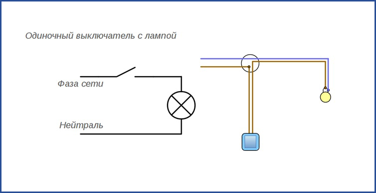
It is very convenient if it is two-color, for example, the phase wire is red, and the zero wire is blue. Summing up what has been said, we can conclude that the circuit for connecting a switch to a light bulb is a set of wires, a light bulb and a switching device.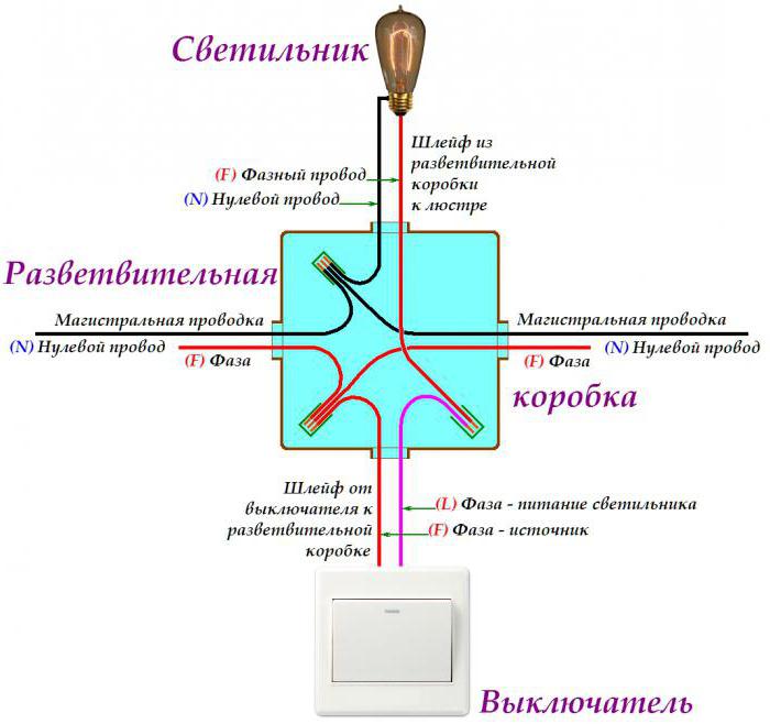
It can be a kettle or, for example, a vacuum cleaner.
They are especially relevant for chandeliers with several lamps.
With grounding pliers, we carefully cling to the upper part of the twist, we bring the electrode to it from below, briefly touch it, achieving the ignition of the arc, and remove it. Inserting only a single-core conductor, the tab is bent, clamping the wire.
Before twisting, the wires are tinned: a layer of rosin or soldering flux is applied. The pass switch, when the key is pressed, switches contact 1 between the other two - 2 and 3.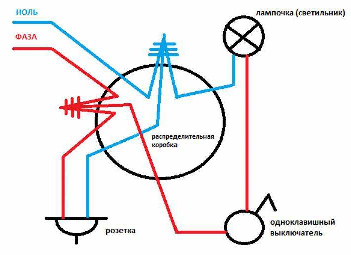
Connection diagram of a switch in a junction box Connecting a wire directly to a lamp or switch is quite simple - it does not require explanation. Their power consumption is higher than that of a simple light bulb, and therefore thin wires can heat up, which is undesirable.
How to connect a single-gang switch? How to install in a socket?
conclusions
The switch is a mandatory component through which the user can control the lamp. At home, different types of switches are used - with one key and several, pass-through and cross, with a dimmer and a motion sensor. They are also classified according to the method of installation. Most often, one- and two-key overhead and built-in devices are used.
The wiring diagram for a switch with a light bulb is similar in all cases. The switch is placed in a phase break of the circuit. All work is carried out according to the above instructions and schemes, in compliance with safety regulations. After installation, you need to check the operability of the circuit.
Previous
LightingHow to make lighting in a bath or sauna with your own hands
Next
Lighting How to properly install and connect a double switch for two bulbs


