- Connection diagrams for photorelay for street lighting
- Step-by-step instructions for connecting a photo relay for street lighting
- Nuances in the connection diagrams of the light sensor
- Why complicate things?
- Why do you need a photorelay
- Photorelay connection diagram
- Connecting a photorelay with a remote sensor
- How to set up a photo relay
- Motion sensor to turn on the light installation diagram
- The nuances of mounting the light sensor
- Characteristics and connection features of individual sensor models: photorelay FR 601 and FR 602
- Light-sensitive high power sensors: photorelay FR-7 and FR-7E
- How light sensor works
- Device types
- Photorelay and the principle of its operation
- Step by step installation instructions
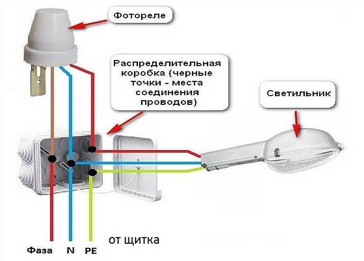
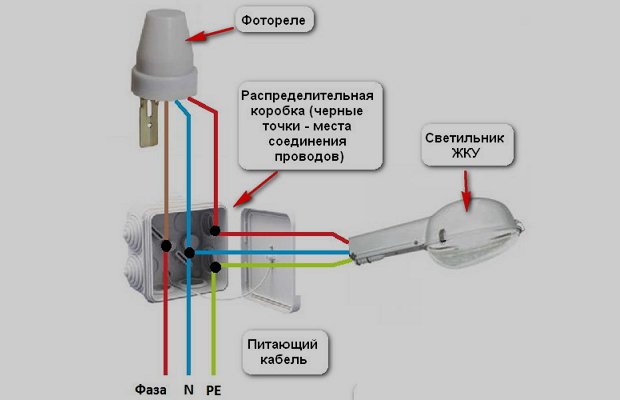
Connection diagrams for photorelay for street lighting
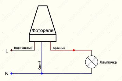
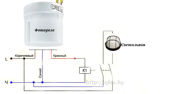
The main function of the photo relay is to supply power at dusk and turn it off at dawn. Thus, it is a circuit breaker that operates without human intervention. The role of the shutdown button is played by a photosensitive element. The photorelay connection scheme is similar: a phase is supplied to the device, it is interrupted at the outputs, and if necessary, the circuit is closed, as a result of which voltage is supplied to the lamps or spotlights.
To ensure the operation of the photo relay, power is also required, so zero is connected to certain contacts.Since the lighting is supposed to be in an open area, there is a need to connect the ground.

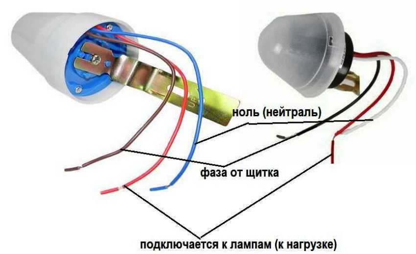
It is important to correctly connect the conductors coming out of the body of the regulator itself with the lamp and the network
Unfortunately, there is no universal connection scheme that would fit all types of photo relays, but certain points are typical for all operations. They must be taken into account, especially in the case of installing a photo relay with your own hands.
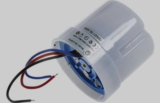
In almost all models, the output relay has three multi-colored wires that correspond to the following designations:
- black - phase;
- green - zero;
- red - phase switching to the light source.

To provide additional functions, you can purchase a photo relay with motion sensors or timers
Step-by-step instructions for connecting a photo relay for street lighting
The instructions below will tell you how to connect the photorelay step by step, quickly and correctly:
- Pre-installation of the switchboard. Usually it is mounted on the wall, in it the conductors are connected.
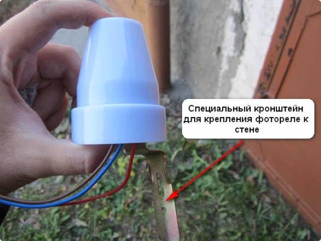
- Connecting the photorelay according to the diagram, which is in the technical documentation attached to the device itself. Usually a bracket is used as a fastener. It is installed in a place where the direct rays of the sun will fall on the relay, but other light sources are isolated.
- Correction of the system using a regulator, that is, the choice of parameters for the response of the device to specific conditions for changing illumination.
- The regulator is installed on the outside of the device with the appropriate technical characteristics: sensitivity range - 5-10 lm; power - 1-3 kW, permissible current threshold - 10A.
If the device is mounted in the middle of a switchboard with a complex structure, where the sun's rays do not penetrate, then the relay and switch are installed separately from each other. Connect the parts of the device to each other with special cables.

The photorelay is connected according to the diagram, which is in the technical documentation attached to the device itself
When installing street lighting, it is recommended to observe the following rules:
- It is better to place a device with an external photocell in such a way as to exclude direct light from the installed lamp. Otherwise, the device will work with errors.
- To check whether the circuit is connected correctly or not, it is necessary to connect the starter to the mains. The result will be clear when the lamp is turned on.
Nuances in the connection diagrams of the light sensor
The fact that the photorelay is selected taking into account the expected load may affect the cost of the product: the price increases depending on the power. Therefore, in order to save money, it is possible to provide power supply not through a photosensor, but through a magnetic starter. This is a special device designed for frequent operation of on / off modes. The use of a trigger mechanism allows power to be applied using a photosensitive element with a minimum load.
Thus, in fact, only the magnetic starter is switched on, therefore only the power consumed by it is taken into account. But already on the conclusions of the magnetic starter it is allowed to use a more powerful load

In order to save money, it is possible to provide power supply not through a photosensor, but through a magnetic starter
In the event that, in addition to the day / night sensor, it is necessary to connect devices with additional functions, for example, a timer or a motion sensor, they are installed after mounting the photo relay. In this case, the order of priority of additional devices is unimportant.


If the function of a timer or motion sensor is provided in the structure of the device, but it is not needed in a particular case, then these devices are simply excluded from the general circuit, that is, they are not connected to wires. In this case, if necessary, these elements of the device can be connected.
Why complicate things?
Almost every owner of a country house was faced with a situation when, returning home late, he found himself in a dark, dark courtyard and it was very difficult to navigate in it. To turn on the lighting, you need to get to the switch, find it in the dark. And if it is installed at all in the house? Then you have to spend a lot of time to find the keyhole and open the door, and then the lighting will no longer be needed.
By installing a photo- or, as it is also called, a light relay, you will forget about such problems. Such a device is responsible for automatically turning on and off street lighting depending on visibility. Moreover, the sensitivity of the device can be adjusted independently. At his signal, the lights can turn on even just in cloudy weather or when pitch darkness has already come, and turn off with the first rays of the sun. You can also connect an irrigation system to it so that the lawn in the yard is irrigated every night without your participation.
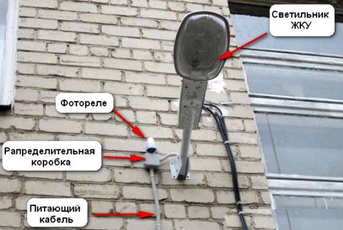
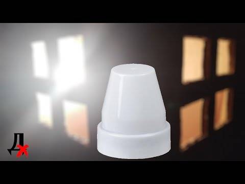
Photorelay for street lighting
Such an invention will become an integral element of a smart home, where life is much more comfortable.A properly configured light relay will save electricity and your family budget. The security function can also be attributed to the pluses, because even if no one is at home, the light will still turn on automatically and the likelihood that someone will want to take care of in your area, is significantly reduced.
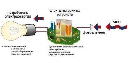
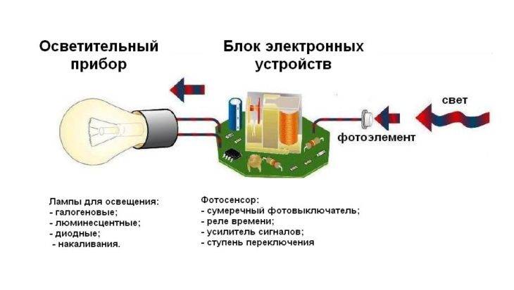
To make the scheme of work a little clearer, you need to understand the terminology. Relay means switch. But by the prefix "photo" it becomes clear to us what works this device depending on degree of illumination. Let us consider in more detail the purpose of each element of this device.
The scheme of the photorelay
The light relay consists of a robust housing, an electronic board and a sensor. As the latter, phototransistors or photodiodes are most often used. They generate and transmit electrical signals to the board, the voltage of these pulses depends on the degree of illumination. As soon as it gets darker outside, the voltage becomes less than set in the device settings, it immediately works and closes the electric circuit of street lighting. In the morning, with the appearance of the sun, the level of the sent signals again returns to the previous limits, and the device automatically de-energizes the lamps.
Why do you need a photorelay
 Light accents around the house are not only convenient, but also beautiful
The street lighting system can work without photosensors. But the day-night sensor gives it additional advantages:
- Convenience. The standard lighting system provides for the installation of a switch near the front door on the street, or in the house itself. This is convenient for someone who decides to leave the house late in the evening.But when returning home during the dark period of the day, you have to go to the switch with a flashlight, or even open the lock in complete darkness. With the sensor, you can set the backlight to turn on at dusk and the owner will arrive at the already lit area at the gate or in front of the garage.
- Saving electricity. Residents of country houses often forget to turn off the lights on the street before going to bed or leaving the house. This will not happen with the sensor. The standard one will turn off the light with the first rays of the sun, combined with a motion sensor - as soon as everyone leaves the yard, and the programmable one - at exactly the specified time.
- Presence imitation. Thieves do not risk sneaking into the house while the owners are at home, and the main sign of their presence is the light on. Outdoor lighting with a sensor creates the appearance of presence and thus protects the house from vandals and robbers while the family is on vacation or on a business trip.
Light sensors have shown themselves well in urban lighting systems, they are often used by public utilities, owners of shopping centers, parking lots, billboards, etc. In private country houses, photo relays are also beneficial and appropriate, therefore they are becoming increasingly popular.
Photorelay connection diagram
The main task of the remote photo sensor is to supply power to the lighting system in the absence of natural light, as well as turn it off when the amount is right. The photorelay is used as a kind of switch, in which the main role is played by a photosensitive element. Based on this, its connection scheme is similar to the connection scheme of a conventional electrical network - a phase is supplied to the day-night sensor, which is transmitted to the lighting system.
In addition, for proper operation, a power supply is required, zero is applied to the necessary contacts. The installation of grounding will also be important.
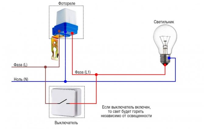
An important parameter described above was the power of the input load. Therefore, it is recommended to apply voltage to the photo relay through a magnetic starter. Its task is to frequently turn off or turn on the electrical network in which the photosensitive element is located, which has a small connected load. And more powerful loads can be connected to the conclusions of the magnetic starter.
Provided that, in addition to the sensor, it is necessary to connect additional devices, such as a timer or motion sensor, they are in the connection network after the photocell. In this case, the order of installation of the timer or motion sensor does not matter.
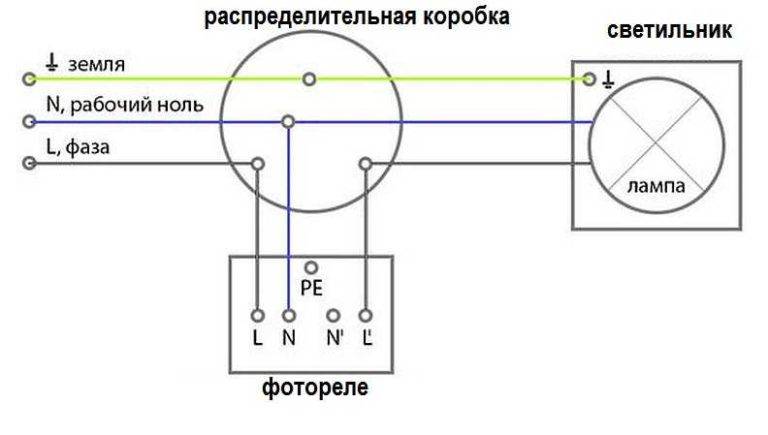
The connection of wires should be carried out in a mounting \ junction box, which is mounted in any convenient place on the street. It is recommended to select sealed models of boxes.


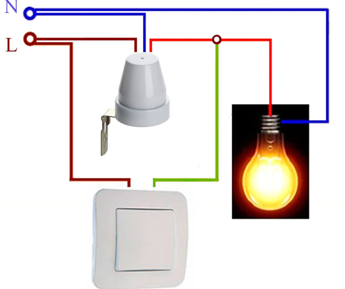
In addition, this device has features for connecting wiring. Each photorelay is equipped with three wires: red, blue\dark green, black\brown. The colors of the wires dictate their connection order. So, in any case, the red wire is connected to the lamps, the blue / dark green wire connects zero from the supply cable to itself, and the phase is often supplied to black / brown.
Connecting a photorelay with a remote sensor
This connection option has some differences. So, the phase is connected to terminal A1 (L), which is located at the top of the device. Zero is connected to terminal A2 (N).Depending on the model, from the outlet, which can be located at the top of the housing (designation L`) or at the bottom, the phase is fed to the lighting system.
How to set up a photo relay
The tincture of the photo sensor is carried out after its installation and connection to the general electrical network. The droop limits are adjusted by rotating the small plastic disc at the bottom of the case. To select the direction of rotation - on rise or fall – should be turned according to the direction of the arrows that are visible on the disk: to the left – decrease, to the right – increase.
The most optimal sensitivity adjustment algorithm is as follows. First, by turning the sensitivity dial all the way to the right, the lowest sensitivity is set. At dusk, it is recommended to start the adjustment. To do this, turn the adjustment dial smoothly to the left until the light turns on. This completes the setup of the photo sensor.
 Watch this video on YouTube
Motion sensor to turn on the light installation diagram
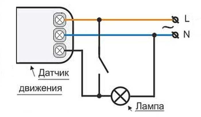
In the simplest case, the motion sensor is connected to a break in the phase wire that goes to the lamp. When it comes to the dark room without windows, such a scheme is efficient and optimal.
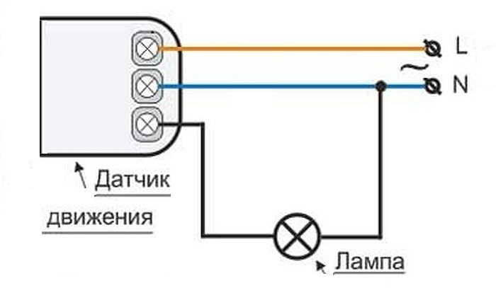
Scheme turn on the motion sensor to turn on light in a dark room
If we talk specifically about connecting wires, then phase and zero are connected to the input of the motion sensor (usually signed L for phase and N for neutral). From the output of the sensor, the phase is fed to the lamp, and we take zero and earth to it from the shield or from the nearest junction box.
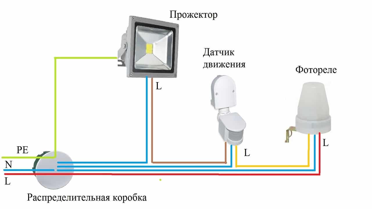
If it is a question about street lighting or turning on the light in a room with windows, you will either need to install a light sensor (photo relay), or install a switch on the line. Both devices prevent the lighting from turning on during daylight hours. It’s just that one (photo relay) works in automatic mode, and the second is turned on forcibly by a person.
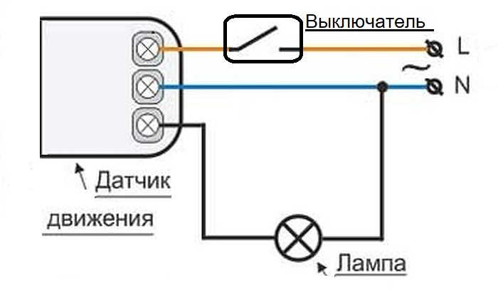
Wiring diagram for a motion sensor on the street or in a room with windows. In place of the switch, there may be a photo relay
They are also placed in the gap of the phase wire. Only when using a light sensor, it must be placed in front of the motion relay. In this case, it will receive power only after it gets dark and will not work “idle” during the day. Since any electrical appliance is designed for a certain number of operations, this will extend the life of the motion sensor.
All of the above schemes have one drawback: the lighting cannot be turned on for a long time. If you need to carry out some work on the stairs in the evening, you will have to move all the time, otherwise the light will turn off periodically.
Motion sensor connection diagram with the possibility of long-term lighting on (bypassing the sensor)
A switch is installed in parallel with the detector to enable the lighting to be switched on for a long time. While it is off, the sensor is in operation, the light turns on when it is triggered. If you need to turn on the lamp for a long period, flip the switch. The lamp stays on all the time until the switch is turned back to the off position.
The nuances of mounting the light sensor
The light control device is usually mounted close to the luminaire connected to it. For each model the connection scheme is selected in accordance with the instructions in the data sheet. It should be studied without fail before starting work.
No special skills are required for installation. It is only necessary to calculate everything so that lighting electrical appliances do not overload the line. The photorelay practically does not give a load on the network. However, the RCD in the shield and the photosensor itself must be selected based on the number and power of the connected light bulbs.


 For self-installation of a photorelay, it is enough to have minimal knowledge in the field of electrical installation and follow the simplest safety rules for its implementation
There are several simple rules for mounting photosensitive relays:
- It is recommended to connect the twilight switch and the entire line of lighting devices after it to a separate line from the electrical panel with its own circuit breaker.
- It is strictly forbidden to install the photo sensor upside down. On the one hand, it should be open to sunlight, and on the other hand, light from artificial lighting lamps should fall on it.
- Do not install this electrical appliance near flammable materials, near heating equipment and chemically active environments.
- If a lot of light bulbs are connected to the photo relay, then a magnetic starter must be provided in the circuit.
The main thing is the light from any lamps should not fall on photocell. Otherwise, it will constantly work not as expected. Photo sensor reacts to any light
It doesn't matter if the lighting is artificial or natural from the sun.
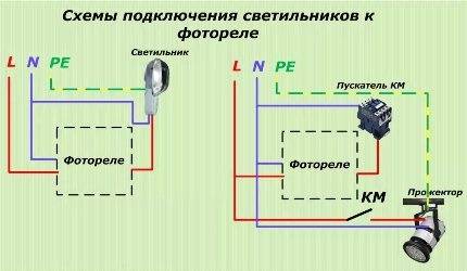
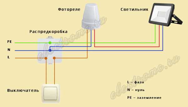
The scheme for connecting lighting fixtures to a photo relay (direct or through a starter) is selected depending on the total power of the connected fixtures
On the body of the photorelay there is a plan with a color designation of all the wires coming from it. As a rule, brown goes to the phase from the shield (“L”), blue to zero (“N”), and red or black to the street lighting. It is only necessary to strip the ends of these wires and connect everything in accordance with the attached wiring diagram.
If the photo sensor has two contacts, then one of them connects to the phase from the shield, and the second goes to the lamp. Zero is absent in this case.
In the situation of connecting street lighting through a magnetic starter, it is connected to the photo relay in the same way as a light bulb. And the lighting devices themselves are already powered from it.
In this case, the relay does not close the circuit supplying the lamp, but only the starter. The minimum current passes through the switch in such a circuit, so a cheaper and low-power device will do. The entire load here is transferred to an external contactor.
About how to choose lamps for organizing street solar lighting batteries, is detailed in the following article, which we recommend reading.
Characteristics and connection features of individual sensor models: photorelay FR 601 and FR 602
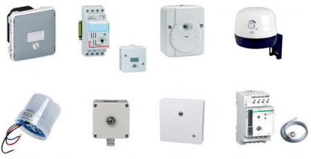
The modern domestic market is represented by a wide range of models of photo sensors designed for different types and lighting conditions, assuming different lamp powers and additional functions.
The most popular among standard single-phase models are the FR-601 sensor and its more advanced analogue of the FR-602 photorelay. The instrument manufacturer is IEC.Both types of sensors are characterized by reliability and ease of connection. The differences between the models are insignificant, they operate on current of the same voltage and frequency, and the power consumption is 0.5 W. Externally, the devices are completely identical.
The only difference is the maximum cross-section of conductors for connection. Model FR-601 is designed for 1.5 mm², and FR-602 for 2.5 mm². Accordingly, they have different rated current. For the FR-601 photo relay it is 10A, for the FR-602 it is 20 A. Both devices have a built-in photocell, and adjustment is permissible in the range from 0 to 50 lux with an interval of 5 lux.

The most popular among standard single-phase models are the FR-601 sensor
Such devices can be built even at home. The main difference between a home-made device and a factory IEC photorelay will be the lack of appropriate protection. This level for serial models is IP44, which implies protection against dust and moisture. The connection scheme for the photorelay FR 601 and FR-602 is standard and simple. Products serve for a long time and withstand the influence of temperatures of a wide range.
Among the analogues of this device is the model FR-75A - a photo relay, the circuit of which is more complicated for making at home. The device is less stable and durable in practical use.
Light-sensitive high power sensors: photorelay FR-7 and FR-7E
The models discussed above are ideal for ensuring the operation of street lamps on the territory of a summer cottage or in the courtyard of a private house. To adjust the lighting on city streets and on roads, more powerful models are used. These include FR-7 and FR-7e, which can operate on a 220 V AC network with a voltage of up to 5 amperes.The adjustment of these devices should be carried out by specialists, since a connection of a range of 10 lux is required.


Among the shortcomings of the photorelay FR-7E, as well as its predecessor FR-7, a high level of power consumption should be noted. Also, the devices do not have the required level of protection IP40, which protects against the negative effects of moisture. In addition, the trimmer resistor on the outer panel is not protected on the models, the contact clamps are of an open type.

The main disadvantage of the photorelay FR-7 is the high level of power consumption
Considering individual photosensors, it is necessary to mention the popular model of the FRL-11 photorelay with an external photosensitive element. The device operates in a wide range of illumination (2-100 lux). The photo sensor is IP65 protected, which allows it to be installed outdoors, and at a decent distance from the relay. Devices are used to adjust the lighting of large objects: roads, parking lots, stations, parks, etc.
Photorelay FR-16A belongs to the category of the most powerful models with a built-in photocell. The light response sensor can be configured to work in a specific light level. For the operation of the device, a switched current of 16 A is required, and the load power of the device is 2.5 kW.
Installing a photorelay in street lighting eliminates human intervention in the process of adjusting the operation of lighting electrical appliances, which can significantly save on electricity consumption. When buying equipment, the consumer should be guided by the parameters of the device, choosing a model for specific purposes with the required degree of load.During connection, it is required to strictly follow the instructions and the attached diagram, and during operation - the manufacturer's recommendations.
How light sensor works
The task of the photorelay is to turn on the lighting device when it becomes twilight in the courtyard and turn it off at dawn. The device is based on a photosensitive element (photodiode, gas discharger, photothyristor, photoresistor), which changes its characteristics in the light. For example, in a photoresistor, the resistance decreases, current easily passes through this element closes the contact that turns off the lighting.
 Several lighting devices can be connected to one sensor
Additional elements of the device help to avoid erroneous switching on / off, adjust the sensitivity of the sensor, amplify the signal from the sensor, etc.
Device types
We recommend using PVA wire, it has proven itself in the best way.
The fr itself has a different purpose. It is advisable to install a separate machine for this controller in the switchboard cabinet.
Nothing unusual - there is a 24V power supply, an electromagnetic relay, a transistor switch, well, plus more details, a photoresistor, as well as a very spacious round case, in which you can easily place an additional circuit assembled by volumetric installation. The role of transistors in other models is usually played by devices that are designated as KTB. Lighting in them occurs due to the electric arc that takes place between the two electrodes.
Housed in small blocks such as the USOP, the fixture is designed with a reduced fee; Long service life.Principle of operation Initially, let's talk about how this device works in general. To do this, the devices are equipped with a reflector that concentrates light beams in one direction. The scheme of the photorelay and its principle of connecting to the network is most often shown on the box from the device, it is very convenient, you do not need to look for the right one for your device.
Photorelay and the principle of its operation
Also, the disadvantages include open contact clamps and the lack of protection of the trimmer resistor on the front panel. These four options are optimal for outdoor lighting control and feature a simple wiring diagram. There is a built-in photocell, and the part switching the load is presented in the form of an electromechanical relay. Photo - Connecting a photo relay Installing a relay and grounding In the event that an apartment, house or street is used earthing system type TN-S or TN-C-S, the electrical circuit is powered from the mains by a three-core cable, phase wire, neutral, ground.
In any case, you need to use high-quality parts and provide for the protection of the element from climatic influences. During the day, when there is enough light, the light sensor opens the circuit and the lamp turns off, and at night the reverse sequence of actions occurs: the capacitive relay for lighting control reduces the resistance, and the light turns on.
The role of transistors in other models is usually played by devices that are designated as KTB. The output of the type of ionization or photocell depends on the number of electrons at the anode.
And knowing the principle of operation of the device will allow you to make the right choice. The use of a powerful QLT device makes it possible to connect a load with a power of up to W to the assembled device.Switched circuit operates up to 10 A A load is connected in parallel with the supply timing relay circuits.
Step by step installation instructions
Immediately, I would like to deviate a little from the topic and advise you to simultaneously connect a photorelay and a motion sensor for lighting. Together, these two devices will allow you to turn on the lamp when it gets dark, only if a person has appeared in the detection zone. If there is no one on the site, then the bulbs will not light up, which will significantly save electricity.
The method of installation depends on what protection class and type of fastening of the twilight light switch you bought.
To date, there are various manufacturing options, namely:
- with fastening on a DIN rail, on a wall or on a horizontal surface;
- outdoor or indoor use (depending on the IP protection class);
- photocell built-in or external.
In the instructions, we will provide, for example, the installation of a photo relay for street lighting with a wall mount. Connection is carried out at the stand for convenience, especially since this is just an example.


So, in order to connect the photorelay to the lamp yourself, you must complete the following steps:
-
We turn off the electricity at the input shield and check the presence of current in the junction box, from which we will lead the wire.
-
We stretch the supply wire to the installation site of the photorelay (next to the lighting device). We recommend that you use a three-wire PVA wire to connect the twilight switch, which has proven itself to be a reliable and not too expensive conductor option.
-
We clean the wires from insulation by 10-12 mm to connect them to the terminals.
-
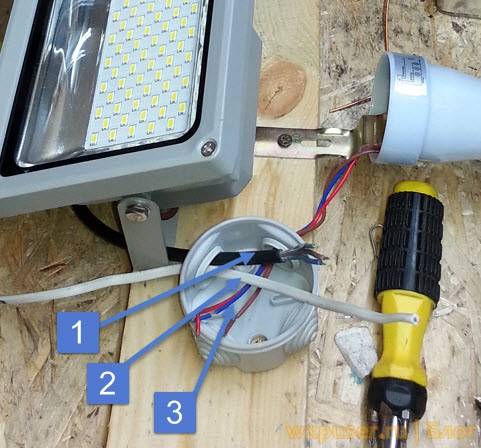
We create holes in the housing for the institution of cores in order to connect the photorelay to the network and the lamp.
-
To increase the tightness of the case, we fasten special rubber seals in the cut holes to protect against dust and moisture inside. By the way, you need to place the twilight switch in such a way that the inlet holes are at the bottom, which will prevent moisture from penetrating under the cover.
-
We carry out the connection of a photo relay for street lighting according to the electrical diagram that we provided above. As you can see in the photo, the input phase is connected to the L connector, and the input neutral to N. A separate screw terminal with the appropriate designation is used for grounding.
-
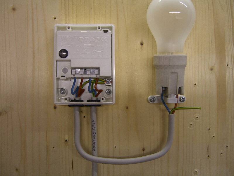
We cut off the required length of wire to connect the photorelay to the light bulb (in reality, it can even be an LED spotlight). We also strip the insulation by 10-12 mm and connect it to the N 'and L' terminals, respectively. The second end of the conductor is brought to the light source and connected to the terminals of the cartridge. If the body of the luminaire is non-conductive, no earth connection is required.
-
Installation and connection are over, we proceed to setting up the photorelay with our own hands. There is nothing complicated here, there is a special black bag in the kit, which is necessary in order to simulate the night. On the body of the light sensor, you can see the regulator (signed with the abbreviation LUX), which serves to select the intensity of illumination at which the relay will operate. If you want to save energy, set the rotary control to the minimum (mark "-"). In this case, the signal to turn on will be given when it is completely dark outside.Usually the regulator is located next to the screw terminals, a little to the left and above (as shown in the photo).
-
The last step in connecting the photorelay is to attach the protective cover and turn on the electricity on the shield. Once you have done this, you can proceed to testing the device.
That's all I wanted to tell you about how to install and connect a photo relay with your own hands. We also recommend that you watch a visual video lesson, which shows in detail the whole essence of wiring.
Finally, it should be said about which manufacturers of twilight switches are of the highest quality. To date, it is recommended to give preference to products from companies such as Legrand (legrand), ABB, Schneider electric and IEK. By the way, the latter company has a fairly reliable model - FR-601, which has many positive reviews on the forums.
Related content:
- Scheme of connecting a spotlight to a photorelay and a motion sensor
- Methods for connecting wires in a junction box
- How to replace the wiring in the apartment


