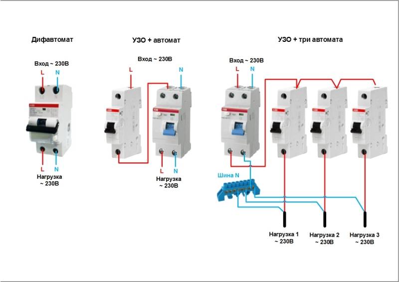
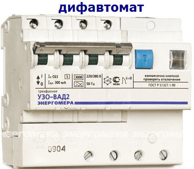
- How does a differential machine work?
- How to connect machines and RCDs correctly
- Connecting machines and RCDs - step by step instructions
- Installing the product
- How to connect correctly: diagrams for a single-phase network
- Installation and connection of elements
- Step-by-step instructions for installing a difavtomat
- What mistakes do electricians make when connecting a protective device
- Key points
- What should be considered when connecting a differential machine
- How is the differential machine
- The main errors of connecting difavtomatov
- Difavtomat in a circuit without grounding
- Choose a method
- The simplest defense
- Reliable protection
- Without grounding
- In a three-phase network
- Features of connection in a private house
- Why does not it work? Looking for mistakes
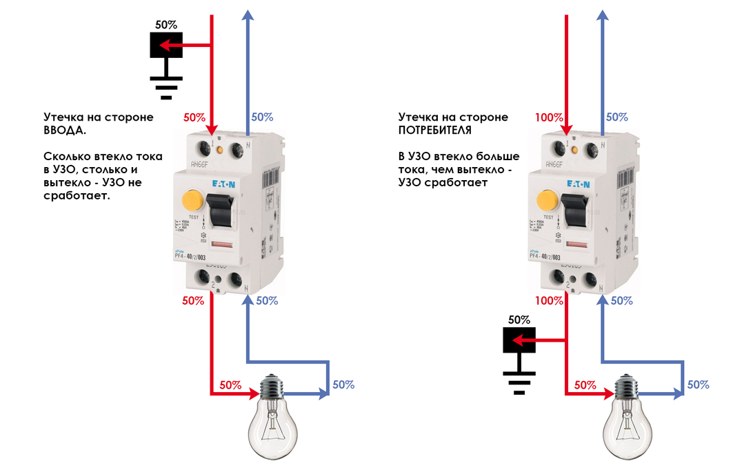
How does a differential machine work?
Since this device in its design has two blocks of different purposes, respectively, these blocks will react differently to disturbances in the electrical circuit. For example, to turn off the circuit when a short circuit or increased loads appear in it, a protection module is triggered, which is similar in principle to a conventional machine. At the heart of this module is a release, it is also a contact release mechanism (independent).
But protection against electric shock to a person is carried out at the expense of another part of the difavtomat - this is the so-called differential protection module. It contains a differential type transformer, which, during network operation, compares two current values: at the input and at the output. If the difference between the two values is significant, that is, there is a threat to human life, then with the help of two elements, namely with the help of an electromagnetic reset coil and an amplifier, the module converts electrical energy into mechanical energy, thereby de-energizing the electrical circuit protected by itself.
How to connect machines and RCDs correctly
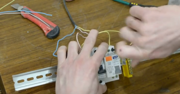
Before starting work on connecting the machines, it is necessary to prepare all the devices:
- Mounting rail (sometimes it is already included with the finished shield). In other cases, you will need to independently measure the desired length and cut it off with scissors for metal.
- Screwdriver.
- Wire cutters.
- Wire stripper.
Connecting machines and RCDs - step by step instructions
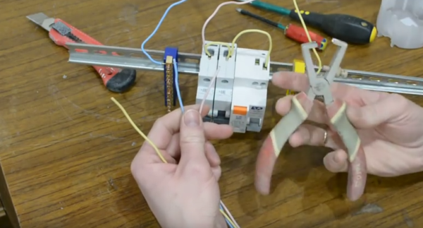
Step 1. To begin with, two tires should be fixed on a metal DIN rail: zero and ground. To do this is simple, you need to insert them at one end, and then snap them into place.
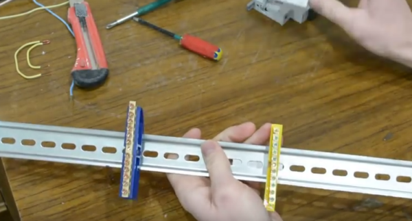 This is how the tires should look after installation
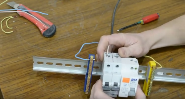
Step 2. Now you need to sequentially fix the machines. At the bottom they have a special latch, which is enough to pull down and then fix the machine on the rail.
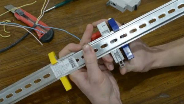 Alternately, it is necessary to fix each machine on the rail
Step 3. Next, you need to take a three-core cable. As a rule, the ground wire is yellow, zero is blue, and the phase is white or pink (as in our case).
It is important not to mix up the wires of the power cable
Step 4First we need to connect the neutral wire to the zero bus. This is done easily - you need to unscrew the bolt with a screwdriver.
 There is a hole for a cable of various sections.
Step 5. Now you need to connect the yellow ground wire to the ground bus.
 This is done in the same way as in the previous version.
Step 6. The next step is to fix the power wire (pink). Contrary to many opinions, it should always come from above. You should connect the wire, but you should not twist it right away - the reason is that then you will have to supply the power wire to all other machines.
 In this step, the wiring is connected "for profit"
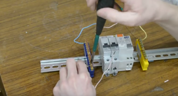
Step 7. Seventh: you need to insert the power wire into the top machine, and then insert one end of the additional jumper into the same hole.
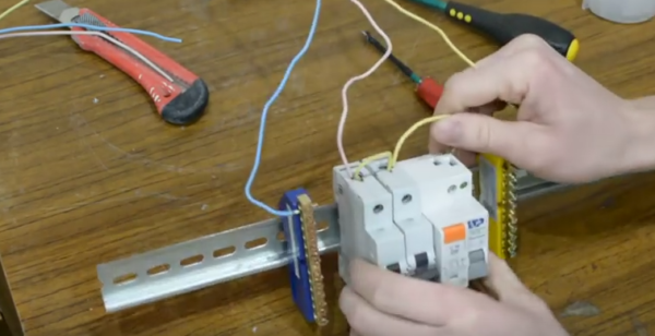 Now you need to insert the jumper into the adjacent machine, and then into the other, alternately tightening the screws
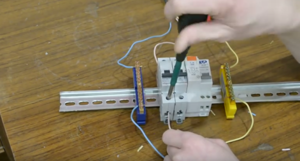
Step 8
Now you need to pay attention to the last differential automaton. On its case, as a rule, there is a wiring diagram
 The first input here will be denoted by the letter N - it will be zero, the second input will be denoted as I (L) - this will be the phase.
Step 9. Now it became clear that the phase is at the second input, which means that the other end of the yellow jumper wire should be fixed there. We tighten the screw by analogy with the previous options.


 Thus, we have completed the connection of the power cable that comes from the shield
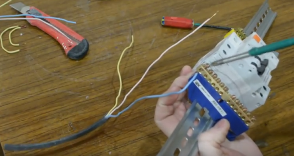
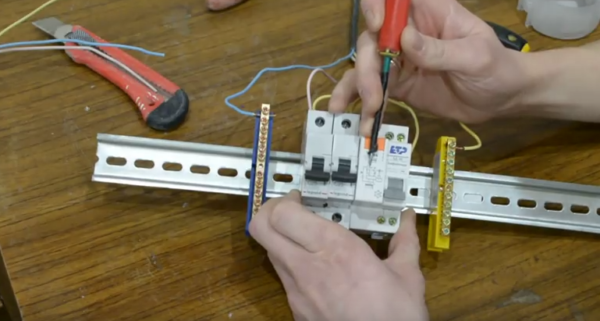
Step 10 Now you need to connect the wires that come from the room. First, you will need to remove a layer of insulation from their ends. A special tool is used to strip the ends of the wires.
 Here you can turn the screw and set the thickness of the wire
Step 11Here, too, you should connect the neutral wire to the corresponding bus.
 You can unscrew any free bolt
Step 12. Now you need to fix the ground wire again.
Tighten the wire carefully, without grabbing the insulation layer.
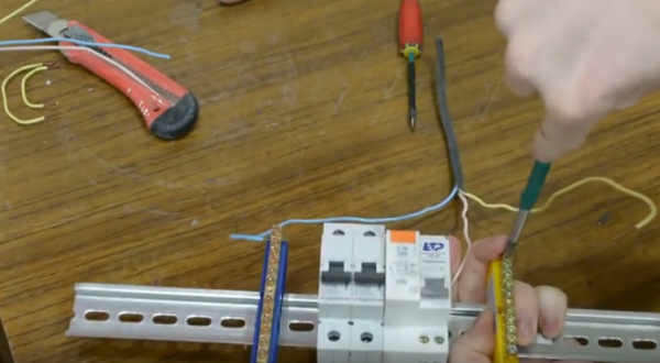
Step 13. Now from the bottom we fix the power wire that comes from the electrical appliance.
 The following wiring by the same analogy will be connected only from below
Step 14. Now you need to take additional wiring, connect it to the zero bus, and then to the first input on the differential machine.
 We fix the wire in the first hole of the difavtomat
Installing the product
After you decide on the connection method, you need to proceed to an equally important stage - installation work. In fact, installing a differential machine is not difficult, the main thing is to do everything correctly and according to the instructions.
So that the readers of "The Electrician Himself" can quickly and without problems install a difavtomat in the shield, we provide the following step-by-step instructions:
Inspect the housing for defects and mechanical damage. Any crack in the housing may cause the product to malfunction.
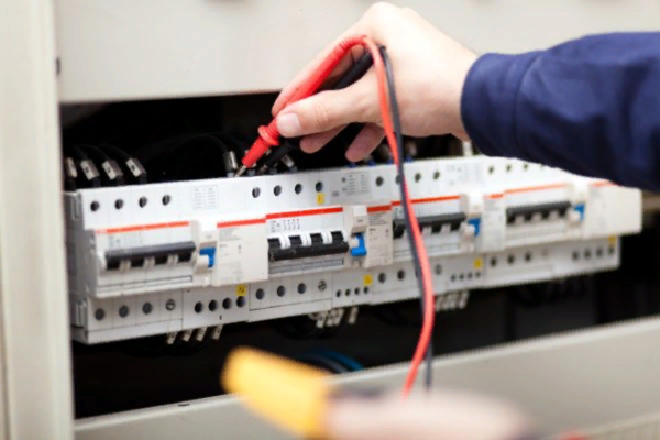
Turn off the electricity in the house and make sure that there is no mains voltage using an indicator screwdriver (or multimeter). We talked about how to check the voltage in the outlet in the corresponding article!
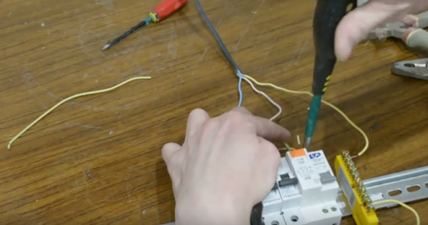
Install difavtomat on a DIN rail, as shown in the photo.
Strip the insulation on the wires to be connected, for this it is recommended to use a stripping tool that will not damage the current-carrying contact.
Connect the phase and neutral conductors, according to the diagram, to special connectors on the body of the difavtomat
Please note that the lead wires must be attached from above.
Turn on the power and check the operation of the device.
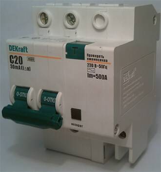
That's the whole technology of installing a differential machine. We recommend using products only from well-known manufacturers: Legrand (legrand), ABB, IEK and Dekraft (dekraft).
We also advise you to be sure to familiarize yourself with the connection errors that we have provided below.
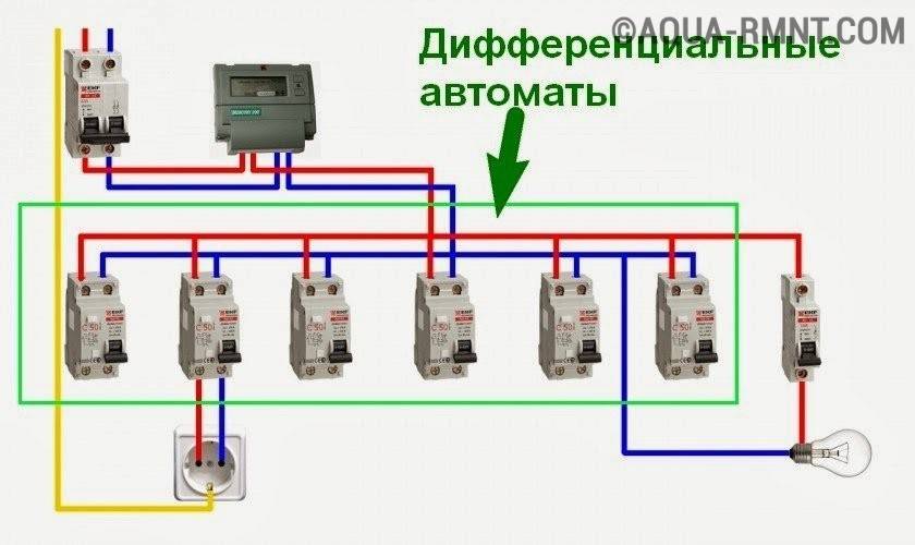
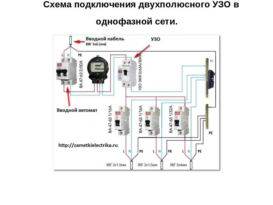
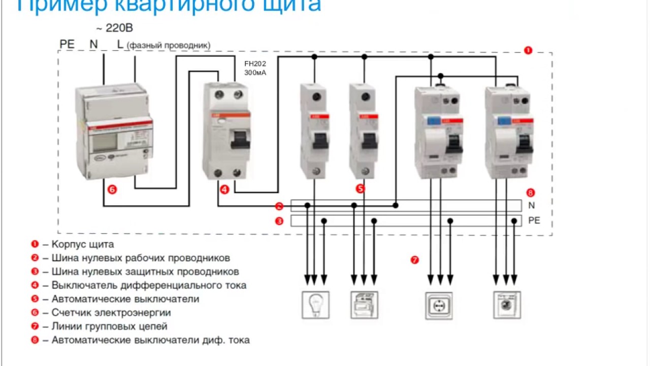
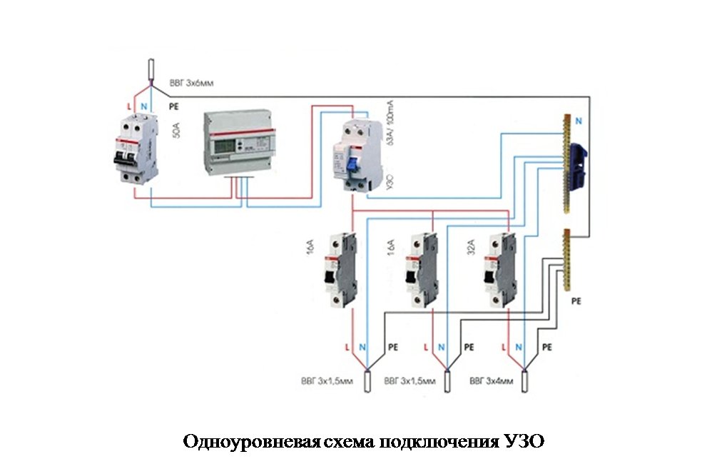
How to connect correctly: diagrams for a single-phase network
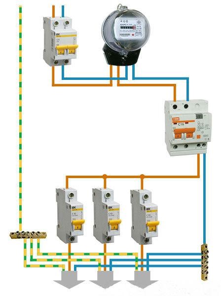
There are 2 connection schemes:
- electric meter - device - consumers;
- electric meter - group device - automatic switch - groups of devices - consumers.
The first scheme is simple. The equipment is connected using the upper terminals to the output of the electric meter. Using the lower terminals, they are connected to consumers.
In the second scheme, it is strictly forbidden to combine the zeros of group devices with each other. This will cause the devices to malfunction.
Most often, the device is installed in a switchboard. There are rules that must be strictly observed:
- the phase is connected to the input of the equipment. It is marked with the Latin letter L or the number 1. You can find the marking on top of the device;


- Latin H means zero input;
- the number 2 or, again, the Latin L, the output of the phase. Located at the bottom of the instrument;
- there is also an exit from zero. It is labeled with the Latin N.
The first scheme is cheaper, does not take up much space in the shield. If the difavtomat works, it will de-energize the entire network. It will be difficult to find flaws in the network.
Installation and connection of elements
All modern machines and RCDs have a unified mount for a standard mounting rail (DIN rail). On the back side they have a plastic stop that snaps onto the bar. Put the device on the rail, hooking it with a notch on the back wall, press the bottom part with your finger. After clicking, the element is set. It remains to connect it. They do it according to the plan. The corresponding wires are inserted into the terminals and the contact is pressed with a screwdriver, tightening the screw. It is not necessary to tighten it strongly - you can transfer the wire.
They work when the power is off, all switches are switched to the “off” position. Try not to grab the wires with both hands. Having connected several elements, turn on the power (input switch), then turn on the installed elements in turn, checking them for the absence of a short circuit (short circuit).
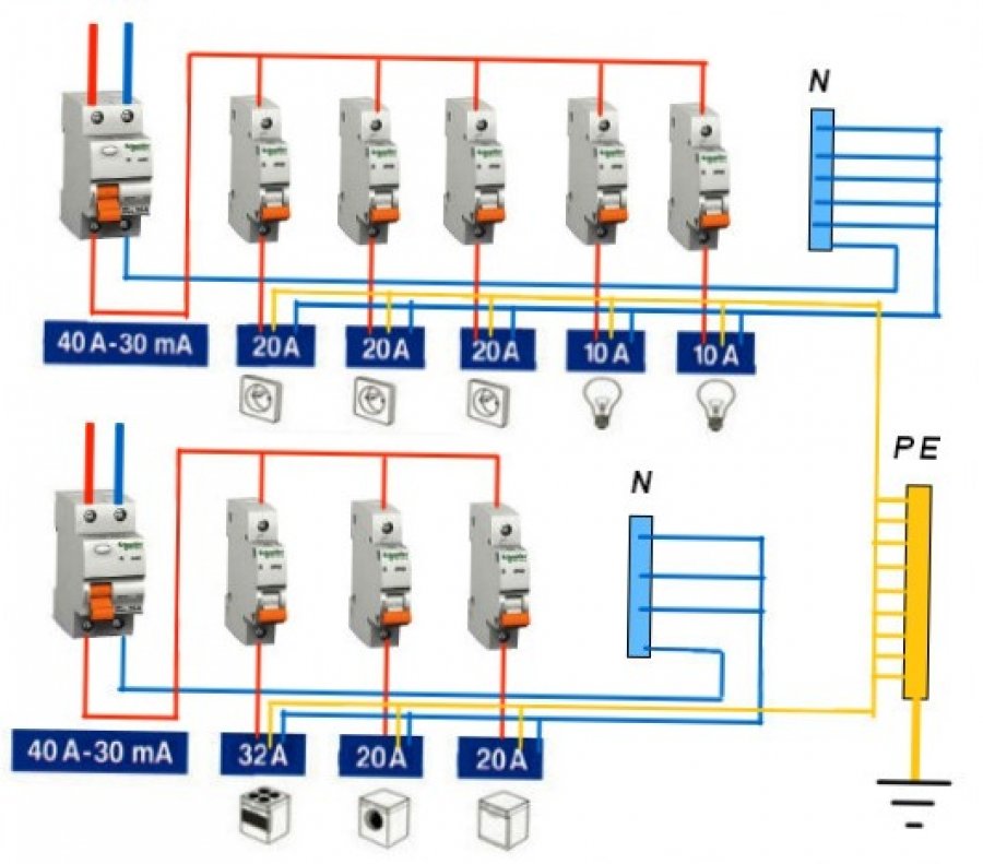
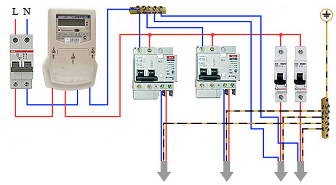
Connection of the input machine and RCD
The phase from the input is fed to the input machine, from its output it goes to the corresponding input of the RCD (put a jumper with a copper wire of the selected section). In some circuits, the neutral wire from the water is fed directly to the corresponding input of the RCD, and from its output it goes to the bus. The phase wire from the output of the protective device is connected to the connecting comb of the machines.
In modern circuits, the input automaton is set to two-pole: it must simultaneously turn off both wires (phase and zero) in order to completely de-energize the network in the event of a malfunction: it is safer and these are the latest electrical safety requirements. Then the RCD switching circuit looks like in the photo below.
When using a two-pole input breaker
See the video for installing an RCD on a DIN rail.
In any scheme, the protective ground wire is connected to its own bus, where similar conductors from electrical appliances are connected.
The presence of grounding is a sign of a safe network and it is vital to do it. Literally
For information on how to properly connect the RCD, see the video tutorial.
When assembling the shield yourself, please note that the input machine and the meter will be sealed by the energy supply organization. If the meter has a special screw on which a seal is attached, then the input machine does not have such devices. If it is not possible to seal it, you will either be denied launch, or the entire shield will be sealed. Therefore, inside the common shield they put a box in one or two places (depending on the size and type of the machine), and an input machine is attached to it. This box is sealed upon acceptance.
Individual machines are installed on rails exactly like RCDs: they are pressed against the rail until they click. Depending on the type of machine (one or two poles - wires), the corresponding wires are connected to them. What are the machines, and how do devices for a single and three-phase network differ, see the video, the choice of the rating of the circuit breaker is described here.
After the required number of devices are installed on the mounting rail, their inputs are connected. As mentioned earlier, this can be done with wire jumpers or a special connecting comb. How the wire connection looks like, see the photo.
Automata in one group are connected by jumpers: the phase comes in common
There are two ways to make jumpers:
- Cut the conductors of the desired segments, expose their edges and bend with an arc. Insert two conductors into one terminal, then tighten.
- Take a sufficiently long conductor, after 4-5 cm, strip 1-1.5 cm of insulation. Take the round-nose pliers and bend the bare conductors so that you get interconnected arcs. Insert these exposed areas into the appropriate sockets and tighten.
They do this, but electricians talk about the poor quality of the connection. It is safer to use special tires. Under them on the case there are special connectors (narrow slots, closer to the front edge), into which the bus contacts are inserted. These tires are sold by the meter, cut into pieces of the required length with ordinary wire cutters. After inserting it and installing the supply conductor in the first of the machines, twist the contacts on all connected devices. See the video on how to connect the machines in the shield using a bus.


A phase wire is connected to the output of the machines, which goes to the load: to household appliances, to sockets, switches, etc. Actually, the assembly of the shield is completed.
Step-by-step instructions for installing a difavtomat
Installing a difavtomat is not difficult and can be done independently without special training.
There should be free access to the place with the block of difavtomatov. It is advisable not to place flammable and explosive objects around it.
The sequence of actions in this case is as follows:
- Check the integrity of the RCBO and the performance of its toggle switches.
- Fix the difavtomat on a special metal DIN rail at its permanent location.
- Turn off the voltage in the apartment and check its absence with an indicator.
- Strip the supply wires in the cable and connect them to the two upper terminals of the difavtomat.The blue color is usually connected to the "zero" of the RCBO, yellow or brown - to the ground loop, and the third color - to the "phase" of the device.
- Connect the wires supplying voltage to the apartment or to subsequent protective devices to the lower terminals of the difavtomat.
- Apply voltage to the RCBO and check the operation of the device.
To test the difavtomat, a special button "T" is provided on it.
When it is pressed, a leakage current appears in the electrical circuit, which should lead to the operation of the device and turn off the voltage. If the RCBO does not respond, it is defective and must be replaced.
In wooden houses, a fireproof shield for a difavtomat is required. It will protect the walls of the house from fire in case of ignition of protective devices.
In the electrical network of the apartment, the difavtomat is only an intermediate link that provides additional protection, so its installation will not cause difficulties.
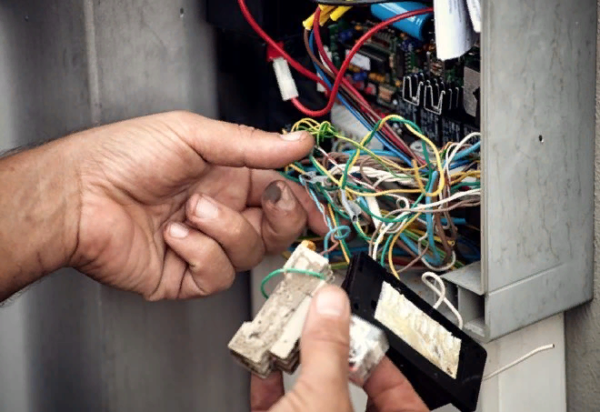
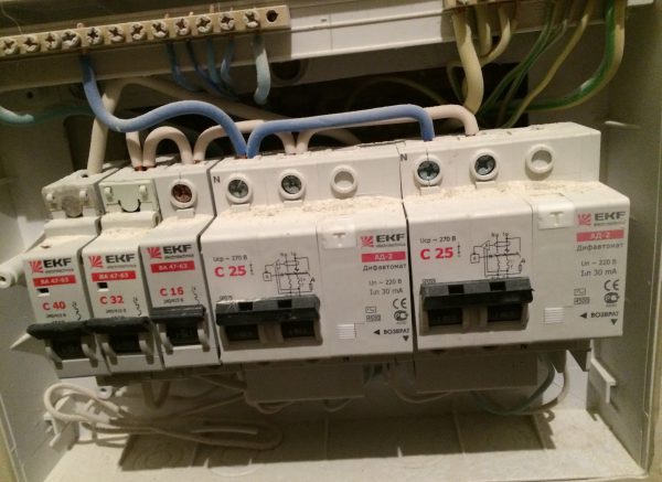
What mistakes do electricians make when connecting a protective device
If, after installing the differential machine, it does not work even with minimal load, it means that mistakes were made.
 Errors in the installation of electrical equipment lead not only to malfunctions of the device, but pose a danger to people's lives
Mistakes in the process of connecting automation are often made by unskilled craftsmen:
- Connections of the zero conductor with the earth cable. The device will not work in this case because the device lever will remain in the same position.
- Connecting the neutral to the load from the neutral bus. With this connection, it will be possible to move the levers to the upper position, but they will still turn off even with minimal load. Therefore, the neutral must be taken only from the output of the RCD.
- Connecting a neutral conductor from the output of the device instead of the load to the bus, and from the bus to the load. With this connection, it will be possible to move the levers to the correct position, but they will also be cut down due to the load. Here it will not be possible to check the device with the "Test" button, because it will not function either. The same consequences await if you confuse the connection of the neutral, connecting it from the bus to the lower terminal, and not to the upper one.
- Messed up connection of neutral conductors and different difavtomatov. Two difautomats will turn on, the "Test" button will also function, but when the load is connected, the devices will immediately turn off.
- If the error is when connecting two neutral cables from different devices, then it will be possible to set the levers to the correct position. However, due to load or pressing the "Test" button, the difautomats will turn off.
 If you confuse the connection of the conductors in the shield, the device will not work correctly
Key points
Regardless of the type of network, when connecting difavtomatov, you should always follow the following rules:
Power wires should always be connected to the device from above, and output wires (to the load) - from below. On most difavtomatov there is a corresponding designation of these connectors and a circuit diagram. Random connection in the reverse order can cost a pretty penny if it leads to the combustion of the machine. If the available length of the wires is not enough, it is best to replace them. In extreme cases, build up or turn over the difautomat on a DIN rail (the main thing is not to get confused during further installation).
The polarity of the contacts must always be observed. According to the international standard, on all devices, the connectors for connecting the neutral wire are designated N, and the phase ones are designated L. The order of current flow is indicated by numbers: 1 - supply wire, 2 - outgoing
Please note that the device may even work if connected incorrectly, however, incorrect polarity will cause it to not respond to overloads and short circuits.
Some electricians out of habit can connect all zeros to one jumper, as many devices' wiring diagrams require this. However, in a difavtomat, such a connection will always cause a conflict, and turn off the power
For normal operation, the zero of each RCBO can only be connected to its own circuit.
What should be considered when connecting a differential machine
Regardless of the type of power supply (single or three phase), some guidelines should be followed to avoid problems during installation:
The power cables must be fixed to the device from the top, and the wires that go to the power consumers - to the bottom. At the same time, on the body of most devices there is already a diagram and connector markings so as not to get confused.
Pay attention to connector labels.
- You have to take into account the polarity of the contacts. At the same time, the equipment for protecting the electrical network, according to the rules, has the following connector designations: phase - L, neutral - N. The lead conductor is marked - 1, and the outgoing conductor - 2. If the contacts are connected incorrectly, the device will remain operational, but will not work at a dangerous moment.
- With some automation, the circuit assumes the possibility of connecting all neutral wires to one jumper. Only in the case of a difavtomat, this is strictly prohibited. Otherwise, there will be a permanent power outage. Therefore, in order to avoid a malfunction, it is necessary to connect each neutral contact only to the branch that is intended for it.
Wrong connection option
A key role in the functioning of the device is played by the correct connection, because most errors cause the combustion of the difavtomat. So, if the length of the wire is not enough, then you will need to increase it.
If necessary, it is allowed to turn the device over on the mounting plate, but then there is a chance to get confused in the process of further installation. This should only be done by people who are familiar with electrical equipment.
How is the differential machine
A difavtomat is an electrical device that is necessary to protect the wiring and products connected to it from large overloads and current leaks. The differential automaton is a special apparatus, consisting of the following functional parts:
- Residual current device, the operation of which is carried out due to the summing up of the reverse current value. During operation, the values of the reverse and input currents are able to create the same magnetic fields, which do not allow disconnecting the equipment for turning off the device. When a current leakage appears in the circuit, the difference between the magnetic fields switches a special relay and the power is automatically turned off.
- A circuit breaker that is equipped with multiple releases.The thermal release switches off the current supply when a small overload is detected on the consumers to which it is connected. The electromagnetic release cuts off the power when a short circuit occurs in the network. In different differential machines, 2 or 4 pole switches are used.
In addition to these nodes, the differential automaton includes a special electronic amplifier and a differential transformer.
Before choosing a difavtomat, it is necessary to correctly check its performance. For this purpose, each device has a special button. When you press it, an artificial simulation of current leakage occurs, which leads to the device turning off. When this condition is not met, then the use of such a difavtomat is not allowed.


In a simple household electrical network, two-pole difavtomatov are used. The device is connected according to a certain principle. From the bottom of the differential machine, zero from the load is connected, and from above it is necessary to connect the power wires.
Multi-pole automata are mounted in the same way, but are used only in three-phase electrical networks with a voltage of 380 volts. Their installation requires much more space on a special rail than for other modules, because the space for the differential protection unit is needed.
For those who are seriously involved in electronics, an article on the practical application and connection diagrams of the LM358 op-amp will be useful.
The main errors of connecting difavtomatov
Sometimes, after connecting the difavtomat, it does not turn on or is cut down when any load is connected. This means that something is done wrong. There are several typical mistakes that occur when assembling the shield yourself:
- The wires of the protective zero (ground) and the working zero (neutral) are combined somewhere. With such an error, the difavtomat does not turn on at all - the levers are not fixed in the upper position. We'll have to look for where the "ground" and "zero" are combined or confused.
- Sometimes, when connecting a difavtomat, zero to the load or to the below located automata is taken not from the output of the device, but directly from the zero bus. In this case, the switches become in working position, but when you try to connect the load, they instantly turn off.
- From the output of the difavtomat, zero is not fed to the load, but goes back to the bus. Zero for the load is also taken from the bus. In this case, the switches become in working position, but the "Test" button does not work and when you try to turn on the load, a shutdown occurs.
- Zero connection mixed up. From the zero bus, the wire must go to the appropriate input, marked with the letter N, which is at the top, not down. From the bottom zero terminal, the wire should go to the load. The symptoms are similar: the switches turn on, the "Test" does not work, when the load is connected, it trips.
- If there are two difavtomatov in the circuit, the neutral wires are mixed up. With such an error, both devices turn on, "Test" works on both devices, but when any load is turned on, it immediately knocks out both machines.
- In the presence of two difautomats, the zeros coming from them were connected somewhere further. In this case, both machines are cocked, but when you press the "test" button of one of them, two devices are cut down at once. A similar situation occurs when any load is turned on.
Now you can not only select and connect a differential circuit breaker, but also understand why it knocks out, what exactly went wrong and correct the situation yourself.
Difavtomat in a circuit without grounding
Not so long ago, the construction technology of any buildings took into account the mandatory installation of a ground loop. All switchboards available in the house were connected to it. In modern construction, grounding equipment is not mandatory. In such buildings and the apartments in them, differential ABs must be installed without fail in order to ensure the necessary level of electrical safety. The difavtomat in such a circuit not only protects the network from malfunctions, but also plays the role of a grounding element, preventing leakage of electric current.
Clearly about the connection of difavtomatov on video:
Choose a method
To begin with, let's deal with the main options for electrical work, because. home electrical wiring can be single-phase (220 V), three-phase (380 V), with or without grounding. In addition, the product can only be installed on the inlet panel in the apartment or on each individual group of wires. Depending on these conditions, the difavtomat connection diagram may be slightly modified, and the device itself will have a different design (two-pole or four-pole).
So, let's consider in order each of the ways to connect a difavtomat in a shield.
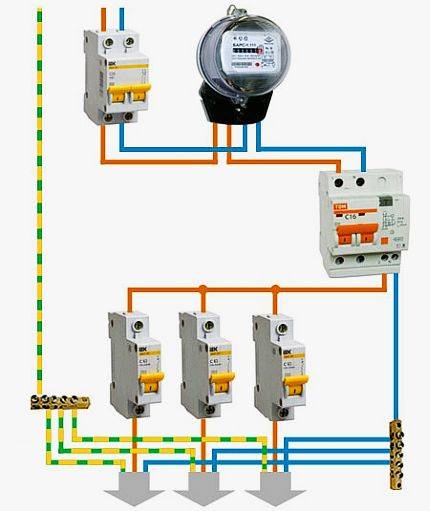
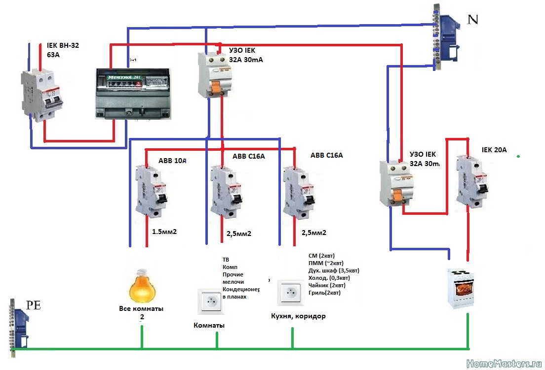
The simplest defense
The easiest installation method is one introductory difavtomat serving all apartment wiring. In this case, you need to buy a powerful device, designed for the current load from all electrical appliances in the room.The disadvantage of such a connection scheme is that if the protection works, it will be problematic to find the problem area yourself, because. the test could be anywhere.
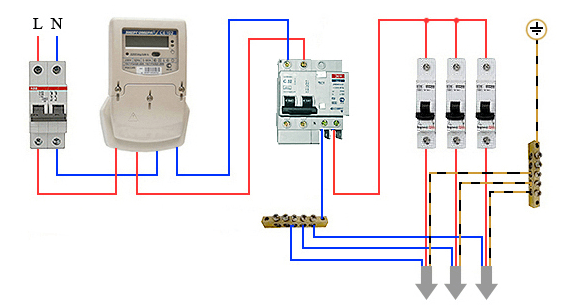
Please note that the ground wire runs separately, connecting to the ground bus, to which all PE conductors from electrical appliances are connected. Also an important point is to connect the neutral conductor. Zero, which is derived from the differential machine, is strictly forbidden to be connected to other zeros of the mains
This is due to the fact that different currents will pass through all zeros, which will cause the device to trip.
Zero, which is derived from the differential machine, is strictly forbidden to be connected to other zeros of the mains. This is due to the fact that different currents will pass through all zeros, which will cause the device to trip.
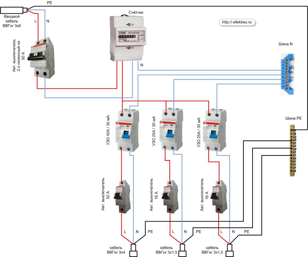
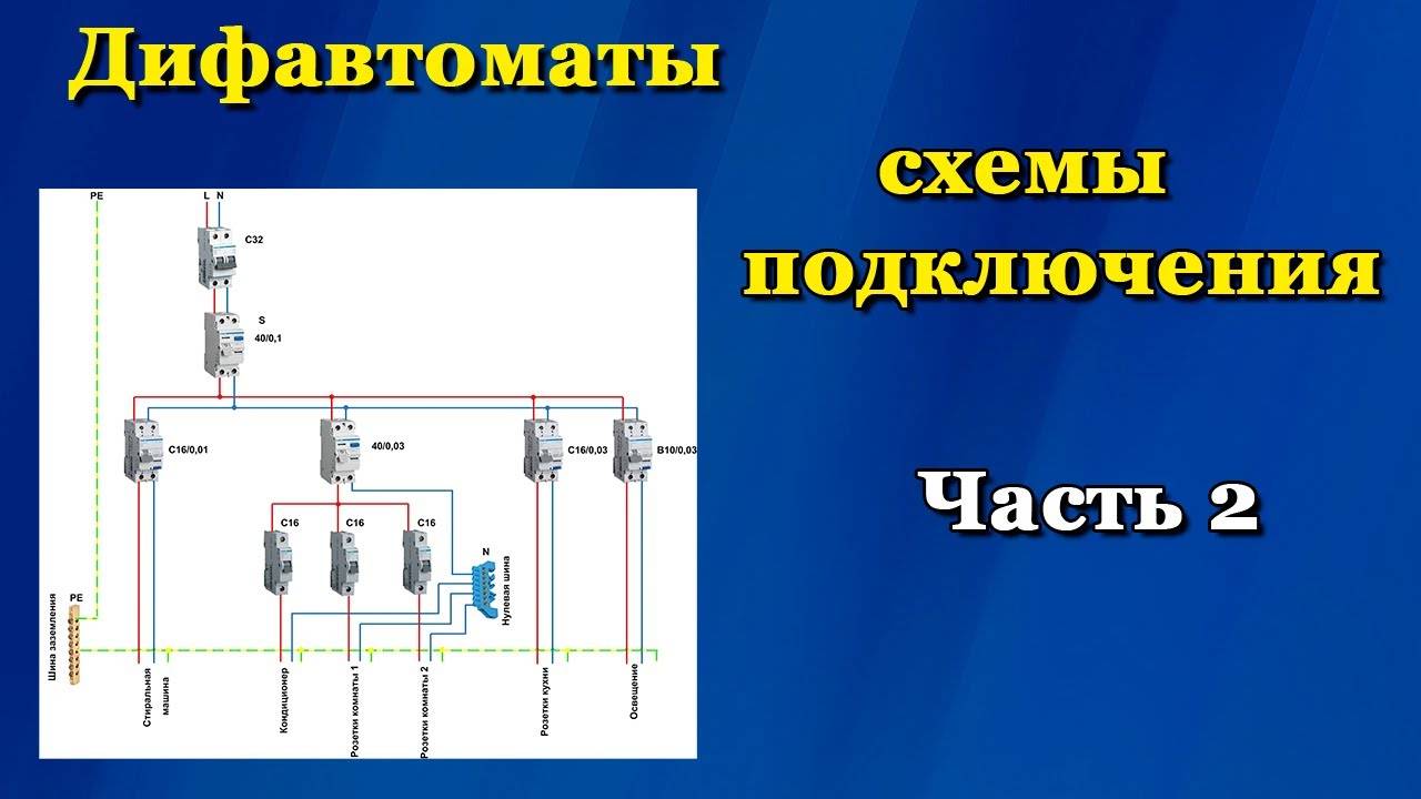
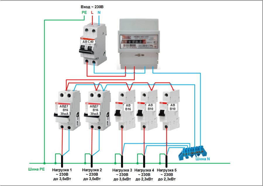
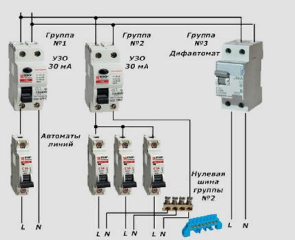
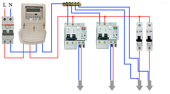
Reliable protection
An improved option for connecting a difavtomat in a house is the following scheme:

As you can see, a separate device is installed on each group of wires, which will only work if a dangerous situation arises in its “section”. At the same time, the rest of the products will not react and will work in their normal mode. The advantage of this connection option is that in the event of a current leakage. short circuit or overload of the electrical network, you can immediately find the problem area and proceed to its repair. The disadvantage of this method of installing a difavtomat is the increased material costs for the purchase of several devices.
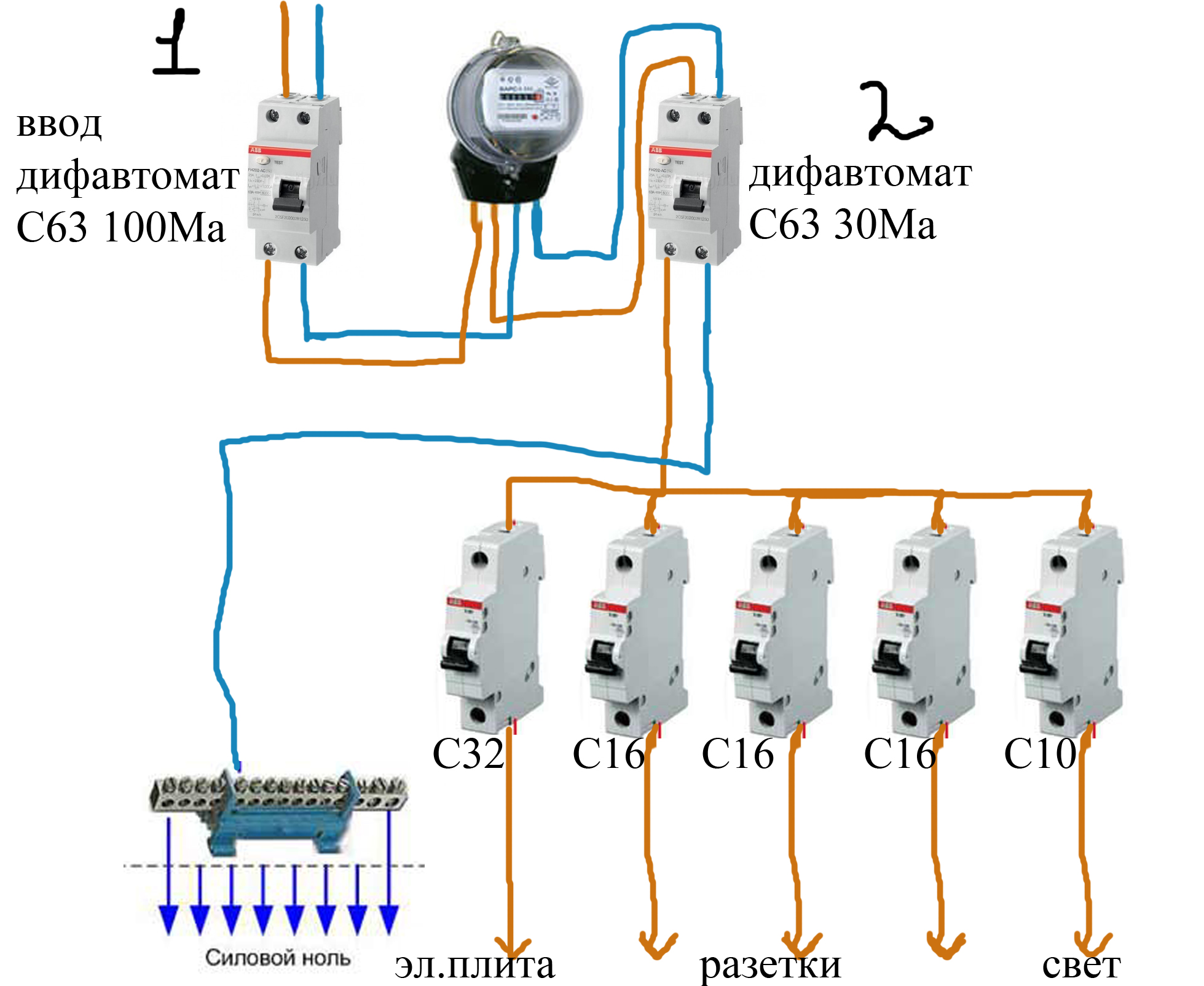
Without grounding
Above, we provided several examples in which a ground contact was present.However, in the country house and in old houses (and, accordingly, with old wiring), a two-wire network was used - phase and zero.
In this case, the difavtomat connection was carried out according to the following principle:
If in your case there is also no "ground", be sure to replace the electrical wiring in the house with a new, safer one.
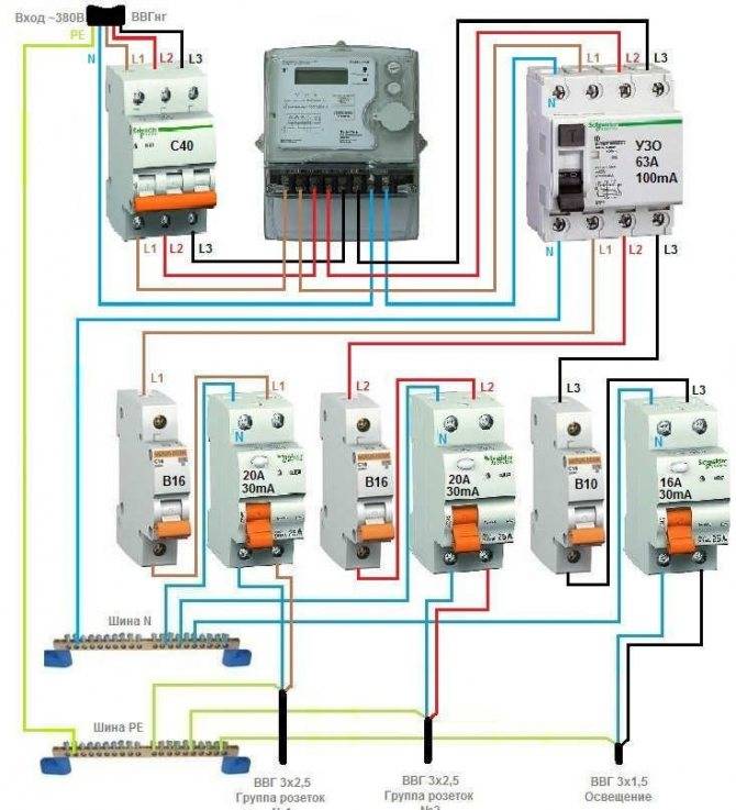
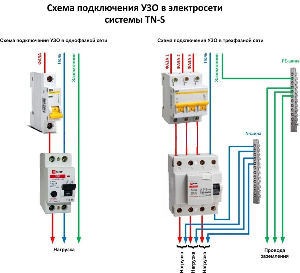
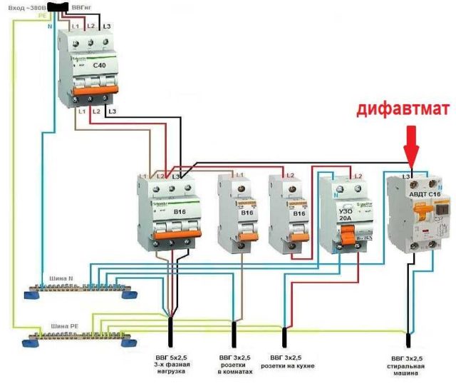
In a three-phase network
If you decide to install a difavtomat in a cottage, garage or modern apartment where a three-phase 380V network is used, in this case you must use a 3-phase automatic. In fact, the circuit will not differ from the previous ones, if you do not take into account the fact that four wires must be connected at the input and output from the case.


The diagram shows how to connect a three-phase difavtomat to the network:

So we provided the existing ways to connect a differential machine with our own hands. The most correct option is the one with grounding and several separately installed devices.
We also recommend watching a visual video instruction with the correct connection of wires:
Features of connection in a private house
The power grid in a country house is not fundamentally different from the apartment, but there are more diverse options. For example, it is easier to install one single device at the input or several residual current devices on the most important lines of the network.
The 300mA introductory device protects all electrical wiring from fire. The RCD is able to respond to the total leakage current from all available lines, despite the fact that in each individual case the norm is observed.
Universal devices, designed to operate at 30mA, are mounted after fire-fighting.The next lines are a bathroom and a children's room (indicator Iу = 10mA).
It is allowed to remake the grounding system in TN-C-S. Independent connection of re-grounding to the neutral is not allowed. If the voltage gets to the neutral wire from the external network, the grounding will become the only one for the surrounding houses, which, with poor-quality work, becomes a frequent cause of fires. Re-grounding is recommended to be performed at the input from the overhead power line.
In country houses, they install the main input and two machines (for sockets and light switches). The boiler is connected to the network using an outlet or a dedicated machine.
Why does not it work? Looking for mistakes
The device is connected in strict accordance with the diagram, but does not work? Looking for errors:
- the wire to zero was combined with the neutral wires of other similar devices. Doing so is strictly prohibited;
- the input wires are connected at the bottom, and the output wires are connected at the top. In this case, it will not be able to function normally;
- zero and ground wire are connected together. The unit will not work correctly, it must be reinstalled;
- during the installation process, they bypassed the protection and connected the H-conductor to the electrical device directly;
- if there are several devices in the circuit, then the phase can be connected to one machine, and zero to another. It is not right.


