- Volume and flow rate
- Bernoulli principle
- How to calculate ventilation pressure?
- Official VENTS ® website
- On the chart
- Additional functions
- Power
- air strike
- Air exchange
- Airflow area
- Tilt and swivel
- Noise level
- Airflow mode
- Control block
- Timer
- Ionizer
- Humidifier
- Certificate
- Bernoulli's Equation of Stationary Motion
- How to determine fan pressure: ways to measure and calculate pressure in a ventilation system
- Pressure in the ventilation system
- air performance
- Pascal's Law
Volume and flow rate
The volume of liquid passing through a certain point at a given time is considered as the volume flow or flow rate. The flow volume is usually expressed in liters per minute (L/min) and is related to the relative pressure of the fluid. For example, 10 liters per minute at 2.7 atm.
The flow rate (fluid velocity) is defined as the average speed at which the fluid moves past a given point. Typically expressed in meters per second (m/s) or meters per minute (m/min). Flow rate is an important factor in sizing hydraulic lines.
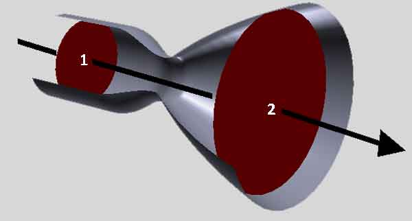
Volume and fluid flow rate are traditionally considered "related" indicators.With the same amount of transmission, the speed may vary depending on the cross section of the passage
Volume and flow rate are often considered simultaneously. Ceteris paribus (with the same input volume), the flow rate increases as the section or size of the pipe decreases, and the flow rate decreases as the section increases.
Thus, a slowdown in the flow rate is noted in the wide parts of the pipelines, and in narrow places, on the contrary, the speed increases. At the same time, the volume of water passing through each of these control points remains unchanged.
Bernoulli principle
The well-known Bernoulli principle is built on the logic that the rise (fall) in the pressure of a fluid fluid is always accompanied by a decrease (increase) in speed. Conversely, an increase (decrease) in fluid velocity leads to a decrease (increase) in pressure.
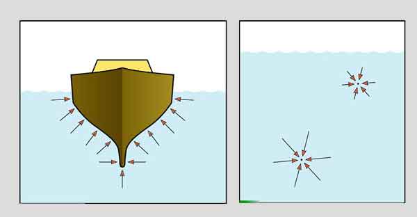
This principle is the basis of a number of familiar plumbing phenomena. As a trivial example, Bernoulli's principle is "guilty" of causing the shower curtain to "pull in" when the user turns on the water.
The difference in pressure outside and inside causes a force on the shower curtain. With this force, the curtain is pulled inward.
Another illustrative example is a perfume bottle with atomizer, when pressing a button creates an area of low pressure due to high air velocity. Air carries liquid with it.
Bernoulli's principle for an aircraft wing: 1 - low pressure; 2 - high pressure; 3 - fast flow; 4 - slow flow; 5 - wing
Bernoulli's principle also shows why windows in a house tend to spontaneously break in hurricanes.In such cases, the extremely high speed of the air outside the window causes the pressure outside to become much less than the pressure inside, where the air remains virtually motionless.
The significant difference in force simply pushes the windows outward, causing the glass to break. So when a major hurricane approaches, one should essentially open the windows as wide as possible to equalize the pressure inside and outside the building.
And a couple more examples when the Bernoulli principle works: the rise of an airplane with the subsequent flight due to the wings and the movement of “curved balls” in baseball.
In both cases, a difference in the speed of air passing past the object from above and below is created. For aircraft wings, the difference in speed is created by the movement of the flaps, in baseball, by the presence of a wavy edge.
How to calculate ventilation pressure?
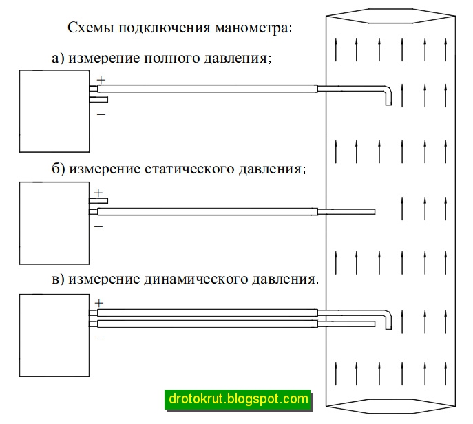
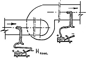
The total inlet head is measured in the cross section of the ventilation duct, located at a distance of two hydraulic duct diameters (2D). In front of the measuring point, ideally, there should be a straight section of the duct with a length of 4D or more and an undisturbed flow.
Then a full pressure receiver is introduced into the ventilation system: at several points in the section in turn - at least 3. Based on the values obtained, the average result is calculated. For fans with a free inlet, Pp, the inlet corresponds to the ambient pressure, and the excess pressure in this case is equal to zero.
If you measure a strong air flow, then the pressure should determine the speed, and then compare it with the size of the section. The higher the speed per unit area and the larger the area itself, the more efficient the fan.
Total pressure at the outlet is a complex concept.The outgoing stream has a heterogeneous structure, which also depends on the operating mode and type of device. The air at the outlet has zones of return movement, which complicates the calculation of pressure and speed.
It is not possible to establish a regularity for the time of occurrence of such a movement. The inhomogeneity of the flow reaches 7–10 D, but the index can be reduced by straightening gratings.


Sometimes there is a rotary elbow or a detachable diffuser at the outlet of the ventilating device. In this case, the flow will be even more inhomogeneous.
The head is then measured by the following method:
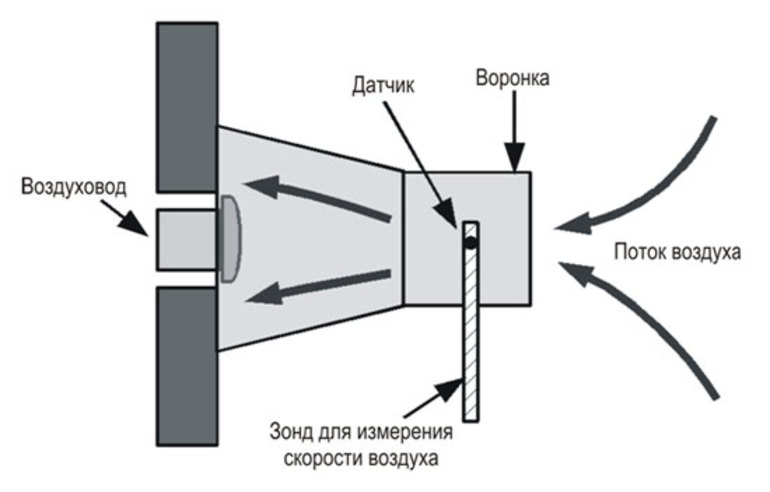
- Behind the fan, the first section is selected and scanned with a probe. Several points measure the average total head and performance. The latter is then compared with the input performance.
- Next, an additional section is selected - in the nearest straight section after exiting the ventilating device. From the beginning of such a fragment, 4-6 D are measured, and if the length of the section is less, then a section is selected at the most distant point. Then take the probe and determine the performance and the average total head.
The calculated losses in the section after the fan are subtracted from the average total pressure in the additional section. Get full outlet pressure.
Then the performance is compared at the input, as well as at the first and additional sections at the output. The input indicator should be considered correct and one of the output indicators is closer in value.
A straight line segment of the required length may not exist. Then a section is chosen that divides the area for measurement into parts with a ratio of 3 to 1. Closer to the fan should be the largest of these parts. Measurements cannot be made in diaphragms, gates, bends and other connections with air disturbance.
In the case of roof fans, Pp is measured only at the inlet, and the static value is determined at the outlet. The high-speed flow after the ventilating device is lost almost completely.
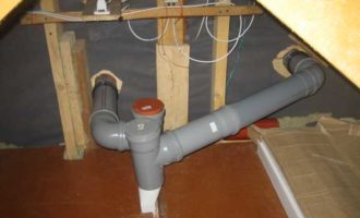
We also recommend reading our material on the choice of pipes for ventilation.
Official VENTS ® website
- Product Catalog
- Menu
-
Household fans
- Menu
- Intelligent fans
- Axial energy-saving fans with low noise level
- Axial inline fans
- Axial wall and ceiling fans
- Axial decorative fans
- Fans with light
- Axial window fans
- Centrifugal fans
- DESIGN CONCEPT: design solutions for domestic ventilation
- Accessories for household fans
-
Industrial and commercial fans
- Menu
- Fans for round ducts
- Fans for rectangular ducts
- Special fans
- Soundproof fans
- Centrifugal fans
- Axial fans
- Roof fans
-
Decentralized ventilation systems with heat recovery
- Menu
- Room reversible units TwinFresh
- Room units Micra
- Decentralized DVUT installations
-
Air handling units
- Menu
- Supply and exhaust units
- Air handling units with heat recovery
- Air handling units AirVENTS
- Energy-saving duct units X-VENT
- Geothermal ventilation systems
-
Air heating systems
- Menu
- Air heating (cooling) units
- Air curtains
- Destratifiers
-
Smoke extraction and ventilation
- Menu
- Roof smoke exhaust fans
- Axial smoke exhaust fans
- Fire dampers
- Fire dampers
- Covered car park ventilation systems
-
Accessories for ventilation systems
- Menu
- Siphon hydraulic
- Silencers
- Filters
- Valves and dampers
- Access doors
- Flexible connectors
- Clamps
- Plate heat exchangers
- Mixing chambers
- Fire damper PL-10
- Water heaters
- Electric heaters
- Water coolers
- Freon coolers
- Mixing units
- Air flow regulators
- Kitchen hoods
- Drainage pumps
- Drip eliminators
-
Electrical accessories
- Menu
- Household fan control units
- Speed controllers
- Temperature controllers
- Electric heater power controllers
- Sensors
- transformers
- Differential pressure switch
- thermostats
- Electric drives
- Communication equipment
- Control panels
-
Air ducts and mounting elements
- Menu
- PVC channel system "PLASTIVENT"
- Connecting and mounting elements
- The system of folding round and flat PVC channels "PLASTIFLEX"
- Flexible air ducts for ventilation, air conditioning, heating systems
- Air ducts for ventilation, heating and air conditioning systems
- Spiral wound ducts
- Semi-rigid FlexiVent ducts
- General information about air ducts
-
Air distribution devices
- Menu
- Lattices
- Diffusers
- Anemostats
- Caps
- Air terminal accessories
- DESIGN CONCEPT: design solutions for domestic ventilation
-
Ventilation kits and ventilators
- Menu
- Ventilation kits
- Wall ventilators
- Window ventilators
- Equipment selection
- Download Center
- Menu
- Download Center
- Catalogs
- Ventilation Tutorial
- Customer Service
- Contacts
- Menu
- Objects with our equipment
- Contacts
- Career
- Objects where our equipment is installed
- Menu
- Administrative buildings, offices
- Residential buildings
- Industrial enterprises
- Medical institutions
- Educational institutions
- Trade, entertainment establishments
- Public catering establishments
- Hotel complexes
- Airports, railway stations
- Athletic facilities
- Vehicle maintenance
- About company
- Menu
- Production
- Innovation and technology
- International associations
- Privacy Policy
- Site Terms of Use
- Ventilation Tips
- Menu
- Determining the need for room air exchange. Design Considerations
- What is pressure loss?
- Fan types
- Fan speed control
- Fan motors
- General recommendations for installation
- Noise characteristics of fans
- What is an IP?
- Price list
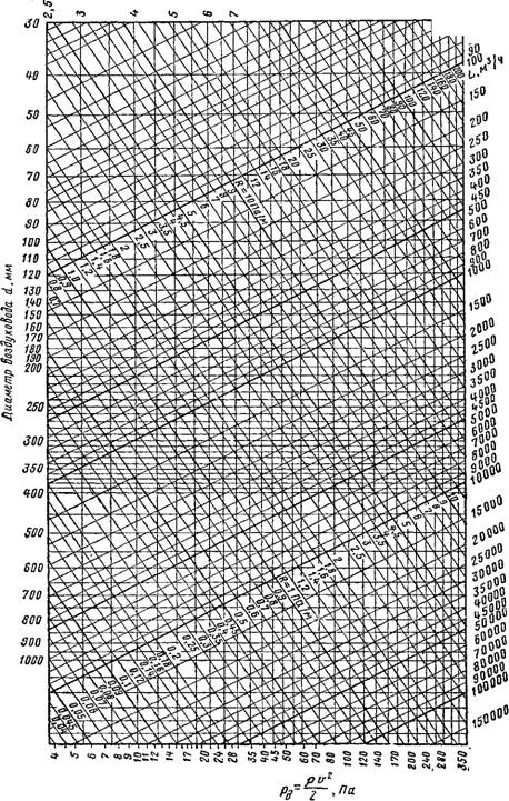
On the chart

Axipal individual fan characteristics chart
1 capacity Q, m3/h 2 total pressure Pv, Pa 3 solid blue lines show curves of fan performance depending on the angle of the impeller blades with an accuracy of one degree 4 blue dotted line shows dynamic pressure without diffuser 5 blue dotted line shows dynamic pressure with diffuser 6 impeller blade angle 7 maximum impeller blade angle 8 solid green lines show fan power consumption curves, kW 9 green dotted lines show average sound pressure levels, dB(A)
The selection of a fan begins with determining its number (size) and synchronous speed. According to the given aerodynamic characteristics (productivity Q and total pressure Pv) on the summary graphs, the size (number) of the fan and the synchronous speed of the fan impeller are determined. In this case, the optimal size of air ducts or openings in walls or ceilings can be taken into account. On the corresponding individual characteristic graph, at the point of intersection of the coordinates of productivity and total pressure (operating point), the fan characteristic curve is found for the corresponding angle of installation of the impeller blades. These curves were drawn with an interval of setting the angle of the blades in one degree. The operating point simultaneously shows the power consumed by the fan (if the operating point and the power consumption curve do not match, interpolation must be carried out) and the average sound pressure level. The dynamic pressure and the dynamic pressure with a diffuser connected are found at the intersection of the corresponding oblique straight lines with a vertical drawn from the capacity Q (values are read on the total pressure scale Pv). Axipal fans can be equipped with electric motors of both domestic and foreign production at the request of the consumer. If the actual operating parameters of the fan (temperature, humidity, absolute atmospheric pressure, air density or actual rotational speed of the electric motor) differ from the parameters at which the aerodynamic characteristics graphs were compiled, the actual aerodynamic characteristics should be clarified. fan characteristics and power consumption according to the following formulas (GOST 10616-90) and the basic laws of ventilation: Q=Q0•n/n0 (1)
Pv = Pv0 • (n/n0 )2 (2)
N=N0•(n/n0)3 , (3)
where Q is the actual productivity, m3/h or m3/s;
Pv is the actual total pressure, Pa; N is the actual power consumption, kW;
n - the actual speed of the electric motor, rpm;
Q0 – performance taken from the graph, m3/h or m3/s;
Pv0 is the total pressure taken from the graph, Pa;
N0 is the power consumption taken from the graph, kW;
n0 - motor speed taken from the graph, rpm. In the case of operation of fans at temperatures exceeding 40 °C, it should be borne in mind that for every 10 °C increase in temperature, the power consumption of the electric motor is reduced by 10%. Thus, at a temperature of +90 °C, the required power of the electric motor should be twice as much as that found from the graphs of aerodynamic characteristics. The heat resistance class of the electric motor insulation must be at least class "F".


Additional functions
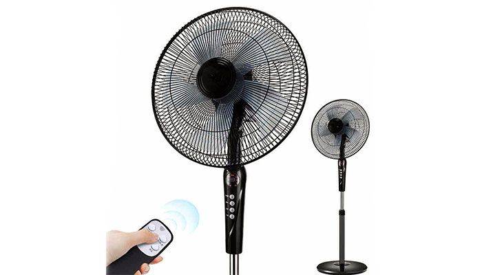
When choosing a floor fan, you will find that almost all models are equipped with various additional options. They greatly facilitate the management and make the operation of climate equipment more comfortable.
The most common features:
- Remote control. With it, you can turn the device on and off, switch operating modes.
- LCD display. The display with up-to-date information simplifies operation and setup of work.
- Timer. Can set the fan running time. It is especially important during falling asleep for automatic shutdown so that it does not work all night.
- Control via Wi-Fi and Bluetooth. With this option, you can control the device from a computer or smartphone.
- Ionization. It saturates the air with negative ions, the air is cleared of microbes, it becomes easier to breathe.
- Air humidification. With the help of the built-in ultrasonic evaporator, it increases the humidity in the room.
- Motion Sensor. Turns the fan on when someone enters the room and turns it off when the room is empty.
Before choosing a floor fan, you need to know its specific characteristics. Below are recommendations based on which you can choose the parameters suitable for cooling your home.
The characteristic that affects the area and intensity of blowing is indicated for axial devices. Choose a fan with blades with a diameter of 10 to 16 centimeters.
Power
This parameter directly depends on the size of the refrigerated room. For a small room up to 20 sq. m, a fan with a power of 40-60 W is suitable, for a room larger than 20 sq. m need power from 60 to 140 watts.
air strike
This characteristic is not always indicated by the manufacturer, as it is believed that it is unimportant. It depends on the diameter of the blades and power, and affects the rate of ventilation of the entire room.
If an air impact of 5 meters is specified, then the maximum distance from the fan at which its operation will be felt will be 5 meters.
Air exchange
This performance it varies from 100 to 3000 cu. m/hour. With its help, knowing the volume of the ventilated room, you can calculate how many air changes can occur.
Different rooms have different norms for the number of air changes. To calculate the required air exchange, you need to multiply the volume of the room by the rate of the number of air changes per hour.
Average rates:
- bedroom - 3;
- living quarters - 3-6;
- kitchen - 15;
- toilet - 6-10;
- bathroom - 7;
- garage - 8.
Airflow area
This characteristic also indicates the performance of the fan. Maximum up to 50 sq. m. But it is better to focus on air exchange.
Tilt and swivel
The tilt angle is responsible for turning the working mechanism up and down and can reach 180 degrees.
The angle of rotation is responsible for the rotation of the working mechanism horizontally and ranges from 90 to 360 degrees.
Most fans have an auto-rotate function - the head with the motor and blades automatically rotates from side to side in a horizontal plane, cooling different parts of the room.
Noise level
The less noise, the more comfortable the fan works. Choose a floor fan with a noise level of 25-30 decibels.
Cheaper models are especially noisy.
Airflow mode
The intensity of the air flow depends on the blowing mode and depends on the number of rotation speeds. They can be from 2 to 8.
Control block
Floor fan control can be touch or mechanical (button). The presence of an information display simplifies operation, showing which mode and functions are enabled at the moment.
With it, you can carry out remote control, which also simplifies its use.
Timer
The timer can only come in handy if you go to bed with the fan on and want it to turn itself off after a certain period of time.
In other cases, when you are in the room, the timer is not needed, it makes no sense to set it up, it is easier to turn it on or off with the knobs.
Ionizer
Air ionization additional useful function. The ionizer saturates the air with negative ions and this has a beneficial effect on the well-being of a person.


Humidifier
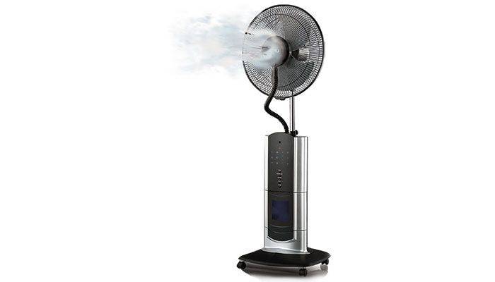
Combining a fan and a humidifier helps keep the humidity in your home at the right level. The price is much higher because of this, since two are combined in one climatic device.
Certificate
To confirm the quality and compliance with the standards for climatic and electrical equipment, check for a certificate.
Bernoulli's Equation of Stationary Motion
One of the most important equations of hydromechanics was obtained in 1738 by the Swiss scientist Daniel Bernoulli (1700-1782). He was the first to describe the motion of an ideal fluid, expressed in the Bernoulli formula.
An ideal fluid is a fluid in which there are no friction forces between the elements of an ideal fluid, as well as between the ideal fluid and the walls of the vessel.
The equation of stationary motion that bears his name is:
where P is the pressure of the liquid, ρ is its density, v is the speed of movement, g is the acceleration of free fall, h is the height at which the element of the liquid is located.
The meaning of the Bernoulli equation is that inside a system filled with liquid (pipeline section) the total energy of each point is always unchanged.
The Bernoulli equation has three terms:
- ρ⋅v2/2 - dynamic pressure - kinetic energy per unit volume of the driving fluid;
- ρ⋅g⋅h - weight pressure - potential energy per unit volume of liquid;
- P - static pressure, in its origin is the work of pressure forces and does not represent a reserve of any special type of energy (“pressure energy”).
This equation explains why in narrow sections of the pipe the flow velocity increases and the pressure on the pipe walls decreases.The maximum pressure in the pipes is set exactly in the place where the pipe has the largest cross section. Narrow parts of the pipe are safe in this regard, but the pressure in them can drop so much that the liquid boils, which can lead to cavitation and destruction of the pipe material.
How to determine fan pressure: ways to measure and calculate pressure in a ventilation system
If you pay enough attention to the comfort in the house, then you will probably agree that air quality should be one of the first places. Fresh air is good for health and thinking. It is not a shame to invite guests to a well-smelling room. Ventilating every room ten times a day is not an easy task, is it?
Much depends on the choice of the fan and, first of all, its pressure. But before determining the pressure of the fan, you need to familiarize yourself with some physical parameters. Read about them in our article.
Thanks to our material, you will study the formulas, learn the types of pressure in the ventilation system. We have given you information about the total head of the fan and two ways in which it can be measured. As a result, you will be able to independently measure all the parameters.
Pressure in the ventilation system
For ventilation to be effective, you need to choose the right fan pressure. There are two options for self-measuring pressure. The first method is direct, in which pressure is measured in different places. The second option is to calculate 2 types of pressure out of 3 and get an unknown value from them.
Pressure (also - pressure) is static, dynamic (high-speed) and full. According to the latter indicator, three categories of fans are distinguished.
The first includes devices with pressure Formulas for calculating the pressure of a fan
The pressure is the ratio of the acting forces and the area on which they are directed. In the case of a ventilation duct, we are talking about air and cross section.
The flow in the channel is distributed unevenly and does not pass at right angles to the cross section. It will not be possible to find out the exact pressure from one measurement; you will have to look for the average value at several points. This must be done both for entering and for exiting the ventilating device.
The total pressure of the fan is determined by the formula Pp = Pp (out) - Pp (in), where:


- Pp (ex.) - total pressure at the outlet of the device;
- Pp (in) - total pressure at the inlet to the device.
For fan static pressure, the formula differs slightly.
It is written as Рst = Рst (output) - Pp (input), where:
- Pst (ex.) - static pressure at the outlet of the device;
- Pp (in) - total pressure at the inlet to the device.
The static head does not reflect the required amount of energy to transfer it to the system, but serves as an additional parameter by which you can find out the total pressure. The last indicator is the main criterion when choosing a fan: both domestic and industrial. The decrease in total head reflects the loss of energy in the system.
The static pressure in the ventilation duct itself is obtained from the difference in static pressure at the inlet and outlet of the ventilation: Pst = Pst 0 - Pst 1. This is a secondary parameter.
The correct choice of a ventilation device includes the following nuances:
- calculation of air flow in the system (m³/s);
- selection of a device based on such a calculation;
- determining the output speed for the selected fan (m/s);
- calculation Pp of the device;
- measurement of static and dynamic head for comparison with full.
To calculate the place for measuring the pressure, they are guided by the hydraulic diameter of the duct. It is determined by the formula: D \u003d 4F / P. F is the cross-sectional area of \u200b\u200bthe pipe, and P is its perimeter. The distance to determine the measurement location at the inlet and outlet is measured by the number D.
air performance
The calculation of the ventilation system begins with the determination of the air capacity (air exchange), measured in cubic meters per hour. For calculations, we need a plan of the object, which indicates the names (appointments) and areas of all rooms.
Fresh air is required only in those rooms where people can stay for a long time: bedrooms, living rooms, offices, etc. Air is not supplied to the corridors, and is removed from the kitchen and bathrooms through exhaust ducts. Thus, the air flow pattern will look like this: fresh air is supplied to the living quarters, from there it (already partially polluted) enters the corridor, from the corridor - to the bathrooms and the kitchen, from where it is removed through the exhaust ventilation, taking with it unpleasant odors and pollutants. Such a scheme of air movement provides air support for "dirty" premises, eliminating the possibility of the spread of unpleasant odors throughout the apartment or cottage.
For each dwelling, the amount of air supplied is determined. The calculation is usually carried out in accordance with and MGSN 3.01.01. Since SNiP sets more stringent requirements, in the calculations we will focus on this document. It states that for residential premises without natural ventilation (that is, where the windows are not opened), the air flow must be at least 60 m³ / h per person.For bedrooms, a lower value is sometimes used - 30 m³ / h per person, since in a state of sleep a person consumes less oxygen (this is permissible according to MGSN, as well as according to SNiP for rooms with natural ventilation). The calculation takes into account only people who are in the room for a long time. For example, if a large company gathers in your living room a couple of times a year, then you do not need to increase the ventilation performance because of them. If you want your guests to feel comfortable, you can install a VAV system that allows you to adjust the air flow separately in each room. With such a system, you can increase the air exchange in the living room by reducing it in the bedroom and other rooms.
After calculating the air exchange for people, we need to calculate the air exchange by multiplicity (this parameter shows how many times a complete change of air occurs in the room within one hour). In order for the air in the room not to stagnate, it is necessary to provide at least a single air exchange.
Thus, to determine the required air flow, we need to calculate two air exchange values: according to number of people and by multiplicities and then choose more from these two values:
-
Calculation of air exchange by the number of people:
L = N * Lnorm, where
L required capacity of supply ventilation, m³/h;
N number of people;
lnorm air consumption per person:
- at rest (sleep) 30 m³/h;
- typical value (according to SNiP) 60 m³/h;
-
Calculation of air exchange by multiplicity:
L=n*S*H, where
L required capacity of supply ventilation, m³/h;
n normalized air exchange rate:
for residential premises - from 1 to 2, for offices - from 2 to 3;S area of the room, m²;
H room height, m;
Having calculated the required air exchange for each serviced room, and adding the obtained values, we will find out the overall performance of the ventilation system. For reference, typical ventilation system performance values:
- For individual rooms and apartments from 100 to 500 m³/h;
- For cottages from 500 to 2000 m³/h;
- For offices from 1000 to 10000 m³/h.
Pascal's Law
The fundamental basis of modern hydraulics was formed when Blaise Pascal was able to discover that the action of fluid pressure is invariable in any direction. The action of liquid pressure is directed at right angles to the surface area.
If a measuring device (manometer) is placed under a layer of liquid at a certain depth and its sensitive element is directed in different directions, the pressure readings will remain unchanged in any position of the manometer.
That is, the pressure of the liquid does not depend on the change of direction. But the fluid pressure at each level depends on the depth parameter. If the pressure gauge is moved closer to the surface of the liquid, the reading will decrease.
Accordingly, when immersed, the measured readings will increase. Moreover, under conditions of doubling the depth, the pressure parameter will also double.
Pascal's law clearly demonstrates the effect of water pressure in the most familiar conditions for modern life.
Hence the logical conclusion: the fluid pressure should be considered a directly proportional value for the depth parameter.
As an example, consider a rectangular container measuring 10x10x10 cm, which is filled with water to a depth of 10 cm, which in terms of volume component will equal 10 cm3 of liquid.


This 10 cm3 volume of water weighs 1 kg.Using the available information and the calculation equation, it is easy to calculate bottom pressure container.
For example: the weight of a column of water with a height of 10 cm and a cross-sectional area of 1 cm2 is 100 g (0.1 kg). Hence the pressure per 1 cm2 area:
P = F / S = 100 / 1 = 100 Pa (0.00099 atmospheres)
If the depth of the water column triples, the weight will already be 3 * 0.1 = 300 g (0.3 kg), and the pressure will triple accordingly.
Thus, the pressure at any depth in a liquid is equal to the weight of the column of liquid at that depth divided by the cross-sectional area of the column.
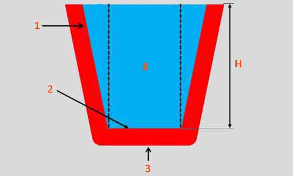
Water column pressure: 1 - wall of the liquid container; 2 - pressure of the liquid column on the bottom of the vessel; 3 - pressure on the base of the container; A, C - areas of pressure on the sidewalls; B - straight water column; H is the height of the liquid column
The volume of fluid that creates pressure is called the hydraulic head of the fluid. The fluid pressure, due to the hydraulic head, also remains dependent on the density of the fluid.