- Constant differential pressure flowmeters (rotameters)
- Differential Pressure Flowmeters
- Flaws
- Volume flow meters
- Electromagnetic flowmeters
- Advantages of electromagnetic flowmeters
- Probe device DRG MZ L
- Purpose
- Modifications
- Measured environment
- Properties
- Usage requirements
- Specifications
- Turbine gas meters.
- How to present evidence correctly
- Archiving readings
- Transfer of readings via the Internet
- Mounting method
- Bandwidth
- Direct method for measuring gas consumption
- What is Gcal
- Features of Gcal for residential high-rise buildings
- Specifics of Gcal for a private house
- Pipeline diameter
- Ultrasonic flow meters
- Advantages of ultrasonic flowmeters
- Flaws
- DETERMINATION OF WATER AND OIL CONTENT
- How to submit meter readings
Constant differential pressure flowmeters (rotameters)
| The principle of operation of flowmeters of this type is based on the fact that the float floating (suspended) in the flow changes its vertical position depending on the gas flow rate. To ensure the linearity of this movement, the flow area of the flow sensor is changed in such a way that the pressure drop remains constant.This is achieved by the fact that the tube in which the float moves is made conical with the expansion of the cone upwards (rotameters of the RM type) or the tube is made with a slot and the piston (melt), rising up, opens a larger flow area for the flow (DPS-7.5, DPS-10 ). Rotameters are produced mainly for technological purposes, as a rule, they have a large value of the main error of 2.5-4%, a small measurement range from 1:5 to 1:10. Rotameters with conical glasses (RM, RMF, RSB), pneumatic (RP, RPF, RPO) and electric (RE, REV) with inductive output are produced. |
Differential Pressure Flowmeters
The principle of operation of such devices is based on the measurement of the pressure drop that occurs when a liquid or gas flow passes through a narrowing device (washer, nozzle). At this point, the flow rate changes, and the pressure increases. Measurements at the point of passage of an obstacle are made using a differential pressure sensor.
Flaws
- Measurements are possible in a small dynamic range.
- Any precipitation on the narrowing device leads to significant errors.
- Mechanical obstacles in the section reduce the reliability of the structure.
These six options are considered the main types of flowmeters for measuring volumes of liquids and gases, air and water.
Izmerkon offers a wide range of industrial air and compressed gas flow meters, including those with a digital interface. You can choose a suitable model, focusing on the description or consulting with managers. Our company from St. Petersburg ensures the shipment of measuring instruments throughout Russia.
Volume flow meters
Devices that determine the volumetric flow rate of a substance can include the following flow meters: variable pressure drop, turbine, ultrasonic, sonic, induction, hydrodynamic), based on nuclear resonance, thermal, ionization, creating various flow marks. Such flowmeters can be divided into two groups.
The first group includes devices in which the sensing element directly converts the flow rate into a measuring signal. This group includes, for example, vane-tachometric flow meters, hot-wire anemometers and other devices.
The second group includes devices in which intermediate measuring parameters are created in the flow, by changing which one can judge the magnitude of the velocity, and, consequently, the volume flow. Such intermediate parameters can be sonic and ultrasonic vibrations excited or propagating in the flow, ionization of the flow, formation of an ion current in a moving medium created under the action of an external magnetic field, etc. This group of flowmeters includes induction, ultrasonic, some thermal, as well as flow meters that create marks in the flow.
At present, vane-tachometric flowmeters with various devices for registering the number of rotor revolutions have become quite widespread in various fields of technology. These flowmeters are universally applicable devices suitable for measuring the flow rates of various substances, regardless of their physical properties.
Induction flowmeters have become quite widespread in the control of flow rates of conductive liquids.
In this application, these flowmeters have very clear advantages over all other types of flowmeters. However, their scope is limited mainly to conductive liquids.
Ultrasonic flowmeters have received little distribution so far. However, these devices are quite promising. Currently, several directions for the development of such devices have been identified, the main ones being:
a) determination of the flow velocity by the phase shift of ultrasonic vibrations;
b) determination of the flow rate by the repetition rate of bursts of ultrasonic vibrations;
c) determination of the flow rate by differential inclusion of two receiving ultrasonic transducers.
These flowmeters are versatile and can be used to control a wide range of liquids, with the exception of some very viscous liquids.
Thermal flow meters have been developed for a relatively long time, and the arsenal of their circuit solutions is quite wide. However, recently a number of new devices have been developed that eliminate the main disadvantages of devices in this group. Such shortcomings are the influence on the readings of the flow meter not only of the flow rate, but also of its temperature and pressure.

Flowmeters, in which special marks are created in the latter to measure the flow rate, constitute a separate group of devices. Flow marks can be created either by intermittent occurrence of an intermediate measuring parameter in the flow (for example, ionization or thermal marks), or by introducing foreign substances into the flow (for example, doses of an opaque powder or doses of a radioactive substance).
These devices have somewhat complicated circuits, but in a number of special cases it is possible to measure the flow velocity only with their help.
A separate group is made up of flow meters that determine the flow rate by velocity head. This group is represented by an extensive and diverse range of devices. Their main advantage is the simplicity of the device. In cases where it is necessary to determine the flow rate with simple means, reliably and with an average level of accuracy, these devices are the most suitable.
The principles of measurement used in the listed devices make it possible to determine the volumetric flow rates of substances in non-stationary flows. To obtain mass flow rates from the readings of such flow meters, it is necessary to know the change in the density of the measured substance. In some flowmeters of this group, the joint inclusion of density sensors with the corresponding sensitive elements of the flowmeters is used. Such systems make it possible to measure mass flow rates.
Below, each of the listed types of volumetric flowmeters is considered in turn.
Electromagnetic flowmeters
At the heart of such devices is Faraday's law (electromagnetic induction). An electromotive force is generated by the action of water or other conductive liquid passing through a magnetic field. It turns out that the liquid flows between the poles of the magnet, creating an EMF, and the device fixes the voltage between the 2 electrodes, thereby measuring the volume of the flow. This device works with minimal errors, provided that purified liquids are transported and does not slow down the flow in any way.
Advantages of electromagnetic flowmeters
- There are no moving and stationary parts in the cross section, which allows you to keep the speed of fluid transportation.
- Measurements can be made in a large dynamic range.
Probe device DRG MZ L
The probe transducer conducts a linear change of gas or vapor into electrical current. In this case, the "area-velocity" method is used. The flowmeter is installed in gas pipelines with a diameter of 100-1000 mm.
The main feature of the DRG.MZL sensor is the presence of a lubricator. Thanks to this, it is not necessary to shut off the gas or steam supply in order to carry out maintenance work.
When using sensors, it is important to consider the chemical composition of the consumables that the device measures. Model DRG.M refers to universal devices
Purpose
The device is used to fix the flow of all varieties gas in the design of the meter SVG.MZ(L). The sensor also allows you to control the amount of water vapor in the design of the SVP.Z(L) meter. The device is widely used in other systems where the highest frequency does not exceed 250 Hz.
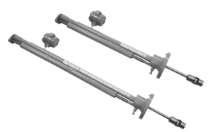
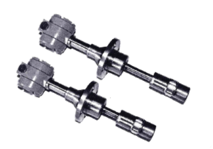
Modifications
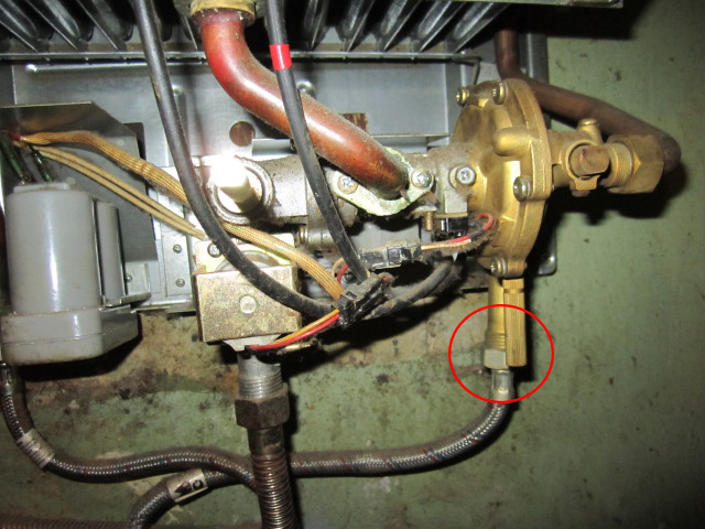
There are 2 types of probe sensor DRG.MZ(L):
- DRG.MZ - installed on the axis of the pipeline (on the left in the picture below);
- DRG.MZL - equipped with a lubricator, thanks to which it is possible to take care of the equipment without turning off the meter (on the right in the picture below).
Measured environment
Excess gas pressure is from 0 to 1.6 MPa. Under normal conditions, the density should not be less than 0.6 kg/m3. The amount of mechanical particles is not more than 50 mg/m3. The temperature of the medium to be measured must be between -4 ºC and +25ºС.The sensor can also be produced in the high temperature range, which reaches +300 ºС.
Properties
The sensor converts the gas flow into a series electrical current in gas pipelines with a diameter of 100 to 1000 mm. The optimal pulse frequency is 0-250 Hz. The current signal in this case is 4-20 mA.
Usage requirements
The device can be mounted both indoors and outdoors (but it is necessary to provide protection against precipitation). The temperature in the place of operation must be between -40°C and +50°C. The optimum air humidity should not exceed 95%.


Specifications
The power required by the sensor to operate is usually less than 0.5 watts. The communication line that connects the flowmeter and the meter is no more than 500 m long.

The optimal diameter of the gas pipeline is in the range from 100 to 1000 mm. For devices with a standard size from 100 to 200 mm, the nominal pressure is from 6.3 to 16.0 MPa. For other varieties, the indicator ranges from 0.0 to 4.0 MPa.
Flowmeters are primarily needed to calculate the amount of fuel in order to further save gas consumption
Therefore, when designing a gasification system in a private house, summer cottage or industrial facilities, special attention must be paid to the choice of this product. After all, the pledged rate of gas consumption, as a rule, is higher than the actual consumption.
Turbine gas meters.
| They are made in the form of a pipe in which a screw turbine is located, as a rule, with a slight overlap of the blades from one another.In the flow part of the housing there are fairings covering a large part of the pipeline section, which provides additional alignment of the flow velocity diagram and an increase in the gas flow velocity. In addition, there is a formation of a turbulent gas flow regime, due to which it ensures the linearity of the characteristics of the gas meter in a large range. The height of the impeller usually does not exceed 25-30% of the radius. At the entrance to the counter in a number of designs, an additional flow straightener is provided, made either in the form of straight blades or in the form of a “thick” disk with holes of different diameters. Installing a grid at the inlet of a turbine meter, as a rule, is not used, since its clogging reduces the area of the flow section of the pipeline, respectively, increases the flow rate, which leads to an increase in meter readings. The conversion of the speed of rotation in the turbines into volumetric values of the amount of gas passed is carried out by transferring the rotation of the turbine through a magnetic coupling to a counting mechanism, in which, by selecting pairs of gears (during calibration), a linear relationship is provided between the rotation speed of the turbine and the amount of gas passed. Another method of obtaining the result of the amount of gas passed, depending on the speed of rotation of the turbine, is to use a magnetic induction transducer to indicate the speed. The blades of the turbine, when passing near the converter, excite an electrical signal in it, so the speed of rotation of the turbine and the frequency of the signal from the converter are proportional. With this method, the signal conversion is carried out in the electronic unit, as well as the calculation of the volume of the passed gas.To ensure the explosion protection of the meter, the power supply must be made with explosion protection. However, the use of an electronic unit simplifies the issue of expanding the measuring range of the meter (for a meter with a mechanical counting mechanism 1:20 or 1:30), since the non-linearity of the meter characteristic, which manifests itself at low flow rates, is easily eliminated by using a piecewise linear approximation of the characteristic (up to 1:50 ), which cannot be done in a counter with a mechanical counting head. To measure the flow, turbine gas meters SG-16M and SG-75M have an explosion-proof pulse output (reed switch) "dry relay contacts" with a frequency of 1 imp./1m3. and non-explosion-proof pulse output (optocoupler) with a pulse frequency of 560 imp/m3. |
How to present evidence correctly
An apartment heat meter is functionally much simpler than a modern mobile phone, but users periodically have misunderstandings about the process of taking and sending display readings.
To prevent such situations, before starting the procedure for taking and transferring readings, it is recommended to carefully study his passport, which provides answers to most questions related to the characteristics and maintenance of the device.
Depending on the design features of the device, data collection is carried out in the following ways:
- From the liquid crystal display by visual fixation of readings from various sections of the menu, which are switched by the button.
- ORTO transmitter, which is included in the basic package of European devices. The method allows you to display on a PC and print extended information about the operation of the device.
- The M-Bus module is included in the delivery of individual meters in order to connect the device to the network of centralized data collection by heat supply organizations. So, a group of devices is combined into a low-current network with a twisted pair cable and connected to a hub that periodically polls them. After that, a report is generated and delivered to the heat supply organization, or displayed on a computer display.
- The radio module supplied with some meters transmits data wirelessly over distances of up to several hundred meters. When the receiver enters the range of the signal, the readings are recorded and delivered to the heat supply organization. So, the receiver is sometimes attached to a garbage truck, which, when following the route, collects data from nearby counters.
Archiving readings
All electronic heat meters store in the archive data on the accumulated indicators of thermal energy consumption, operating and idle time, coolant temperature in the forward and return pipelines, total operating time and error codes.
By default, the device is configured for various archiving modes:
- hourly;
- daily;
- monthly;
- annual.
Some of the data, such as total operating time and error codes, can only be read using a PC and special software installed on it.
Transfer of readings via the Internet
One of the most convenient ways to transfer readings of consumed heat energy to institutions for its accounting is transmission via the Internet.Its convenience and practicality lies in the ability to independently control payments and debts, as well as track heat consumption in different periods without staying in queues and spending a small amount of time.
To do this, you must have a personal computer connected to the network and the address of the website of the controlling organization, as well as the login and password of your personal account, after entering which a form for entering readings will open. To prevent the occurrence of disagreements in the event of a possible failure or malfunction on the site, it is advisable to take “screenshots” of the screen after entering information.
Mounting method
Considering the characteristics of the medium to be measured, the installation conditions of the flowmeter must also be considered. There are 3 main installation methods
- Cut-in flowmeters. Such devices are a ready-made small section of the pipeline with a flow meter installed on it. To install such a device, it is necessary either to remove a section of pipe and install a flow meter in this place, or to mount it on a bypass pipeline. The advantage of tie-in flowmeters is their relatively low cost (however, only if we are talking about small pipeline diameters). The downside is the inconvenience of installation - the tie-in requires some effort, takes a lot of time and, of course, requires a stop in production. In addition, inline flowmeters are not suitable for use on large diameter pipelines. This type of flowmeter includes, for example, the VA 420.
- Submersible flow meters.There is no need to cut an entire section of piping or install a bypass connection to install these units. Installation is done by drilling a small hole in the wall of the pipeline, inserting the flowmeter rod into it and fixing the device in this position. You can read more about installing a submersible flowmeter in the corresponding article. The advantages of this type of devices are ease of installation and relatively low cost. In addition, these devices can be easily used on pipelines of large diameters. For example, the length of the rod for some versions of the SS 20.600 flowmeter allows it to be used in pipelines with a diameter of up to 2 meters. The disadvantage is that these devices are not very convenient to use on extremely small pipelines - with a diameter value of 1/2 "and it is less preferable to use in-line flow meters.
Overhead flow meters. The principle of operation of these flowmeters does not require direct access to the measured medium - the measurement is made through the pipeline wall, usually by the ultrasonic method. The installation of these flowmeters is the most convenient and simple, but their cost is usually several times higher than that of submersible and mortise meters, so it makes sense to use them only if there is no way to violate the integrity of the pipeline.
Bandwidth
The main parameter that the buyer should pay attention to is the throughput of the device. Before purchasing, the owner must determine the maximum gas consumption in the apartment or in the house
It is indicated in the passports for household appliances (gas stove, water heater, etc.). Gas consumption must be summed up. This value will be the main one when buying a counter.This indicator of the gas meter cannot be less than the total.
There are three types of devices available:
- To connect one consumer, devices with a maximum throughput of 2.5 m3 / h are installed. The scoreboard will read G-1.6;
- A meter with the designation G-2.5 is installed when consumers are connected to the main line with a gas flow rate of not more than 4 m3;
- For consumers with high hourly consumption, G-4 meters are installed. They are able to skip 6.10 or 16 m3 per hour.
In addition to throughput, the design must meet the conditions:
- The gas meter is designed for a network operating pressure of not more than 50 kPa;
- Fuel temperature can vary within -300 to +500 C;
- The ambient temperature ranges from -400 to + 500 C;
- The decrease in pressure does not exceed 200 Pa;
- Verification is performed every 10 years;
- Measurement error does not exceed plus or minus 3%;
- Sensitivity - 0.0032 m3/hour;
- The service life of the gas meter is at least 24 years.
The buyer should pay attention to the dimensions of the devices. They should not be too heavy and large so as not to take up much space.
There are many types of blue fuel metering devices on the Russian market. In order for the meter to meet all the requirements of the consumer, it is necessary to take into account all the parameters of the equipment installed in the house or apartment.
Direct method for measuring gas consumption
The volume of gas is calculated in cubic meters, other units of mass are less commonly used, such as tons or kilograms, as a rule, for process gases.
The direct method is the only method that provides a direct measurement of the volume of gas passing through.
The weaknesses of instruments that calculate the volumetric or mass flow rate of a substance include:
- Limited performance of flowmeters in contaminated gas conditions.
- There is a high probability of failure due to partial flow blockage or pneumatic shock.
- The high cost of rotary meters compared to other devices.
- Large devices.
Numerous advantages of this method cover the listed disadvantages, due to which it has also received the greatest distribution in terms of the number of installed meters.
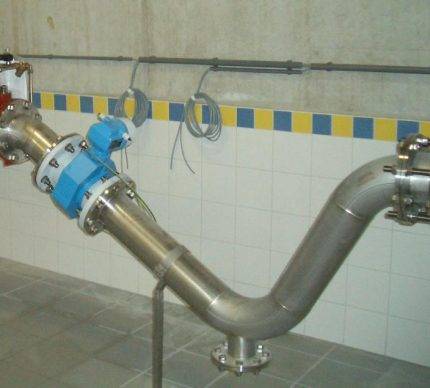 Using a flow meter, you can calculate the volume or mass of a substance per unit of time. Installation on a sloping section of the pipeline will reduce the measurement error
Among them - direct measurement of the volume of gas, the absence of dependence on the distortion of the graph of flow rates, both at the inlet and outlet, which allows to reduce GVG. The range width is up to 1:100. For this purpose, membrane and rotary type devices are used. They can be used in rooms with installed impulse-type boilers.
What is Gcal
 The cost of heating is important for residents of high-rise buildings with a central supply of coolant
The term gigacalorie means a unit of measurement of thermal energy in heating. This energy within the premises is transmitted by convection from batteries to objects, radiated into the air. A calorie is the amount of energy needed to heat 1 gram of water by 1 degree at atmospheric pressure.


To calculate thermal energy, another unit is used - Gcal, equal to 1 billion calories. The average heat consumption per 1 sq. m. in Gcal in the Russian Federation is 0.9342 Gcal/month. If we translate the indicator into other values, 1 Gcal will be equal to:
- 1162.2 kWh;
- heating 1 thousand tons of water to +1 degree.
The value was approved in 1995.
Features of Gcal for residential high-rise buildings
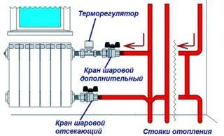 The thermostat allows you to control the flow of coolant and temperature
If a multi-apartment type of building is not equipped with a common house or individual meter, heat energy is calculated based on the area of the premises. When there is a metering device, horizontal or serial wiring of the route, the residents independently determine the amount of thermal energy. For this are used:
- Throttling radiators. When the passability is limited, the temperature decreases, and energy consumption decreases.
- There is a common thermostat on the return line. The flow rate of the coolant depends on the temperature in the apartment. With a low flow rate, the temperature is higher, with a large flow rate, it is lower.
An apartment in a new building is mainly equipped with an individual meter.
Specifics of Gcal for a private house
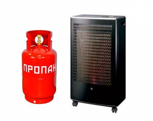
 The cheapest fuel in terms of gigacalories are pellets
The material spent on heating, the tariff determines for private buildings. According to averaged data, the cost of 1 Gcal is:
- gas - natural 3.3 thousand rubles, liquefied 520 rubles;
- solid fuel - coal 550 rubles, pellets 1.8 thousand rubles;
- diesel - 3270 rubles;
- electricity - 4.3 thousand rubles.
Pipeline diameter
Regardless of whether a tie-in, insertion, or clamp-on meter is to be used, the diameter of the pipeline in the area where the meter is to be installed must be specified.
When choosing an inline flowmeter, the diameter of the pipeline is one of the main parameters, since these devices differ in the diameter of the built-in measuring section.With submersible flowmeters, it may seem that the diameter does not matter in any application, since the flowmeter probe can be immersed in the flow at any diameter, however, due to the fact that the sensing element of the device (located at the end of the probe) must be placed exactly in the center of the pipeline, make sure that the length of the probe is sufficient for installation in a particular area. Also, when calculating the minimum required length of the probe, it should be remembered that part of it will fall on the mounting parts: a half-grip and a ball valve.
Let's say the outer diameter of the pipeline is 200 mm. This means that the probe will need to be immersed by 100 mm. Another 100-120 mm will be required for installation. Thus, the minimum probe length for a given diameter should be 220 mm. Most flowmeters are available in various designs that differ in probe length. So for the flowmeter VA 400 there are versions with a length of 120, 220, 300 and 400 mm.
Ultrasonic flow meters
Flowmeters of this type are supplemented with ultrasonic signal transmitters. The speed of the signal from the transmitter to the receiver will change every time the fluid moves. If the ultrasonic signal goes in the direction of the flow, then the time decreases, if it goes against it, it increases. By the difference in the time of signal passage along the flow and against it, the volumetric flow rate of the liquid is calculated. As a rule, such devices are equipped with an analog output and a microprocessor control unit, and all displayed data is displayed on an LED display.
Advantages of ultrasonic flowmeters
- Vibration and shock resistant.
- Stable durable body.
- Suitable for oil refining industry and cooling systems.
- Perform measurements of the flow of water and liquids similar to water in physical properties.
- They work in the average dynamic range of measurements.
- Can be mounted on pipelines of large diameters.
Flaws
- Increased sensitivity to vibrations.
- Susceptibility to precipitation that absorbs or reflects ultrasound.
- Sensitivity to flow distortions.
DETERMINATION OF WATER AND OIL CONTENT
One of the indirect methods for measuring oil water cut, based on the dependence of the dielectric constant of the water-oil mixture on the dielectric properties of its components (oil and water), received the greatest. As is known, anhydrous oil is a good dielectric and has a dielectric constant , while the dielectric constant of mineralized water reaches . Such a difference in the permittivity of water and oil makes it possible to create a moisture meter of relatively high sensitivity. The principle of operation of such a moisture meter is to measure the capacitance of a capacitor formed by two electrodes immersed in the analyzed water-oil mixture.
A unified moisture meter of this type for oil (UHN) allows you to continuously monitor and record the volumetric water content in the oil flow with an error of 2.5 to 4%.
The scheme of the capacitive sensor is shown in Figure 3.3. The upper tap of the sensor shows the output for measuring the capacitance of the capacitor, and the lower tap shows the connection of an electrothermometer T with a temperature bridge. To protect against corrosion and wax deposits, the body is coated on the inside with epoxy resin or bakelite varnish. An inner electrode 3 is mounted on the upper flange 6, a feature of which is the presence of a regulator of its length, acting with the help of a rotating rod.The role of the insulator is performed by a glass pipe 2, which, using a special ring 8 and a steel pipe 7, is attached to the upper flange 6. Inside the glass pipe, a layer of silver is sprayed over a length of 200 mm, which is the internal electrode 3 of the sensor. By rotating the handwheel 5 together with the rod, it is possible to extend the metal cylinder 9 from the electrode to the required length, which is in contact with the silver coating, thus adjusting the moisture meter to measure different grades of oil with different water cut. The scale of the moisture meter located on the top flange is adjusted as a percentage of the volumetric water content. The accuracy of measuring the amount of formation water and oil with this device is significantly affected by: 1) a change in the temperature of the oil-water mixture; 2) the degree of homogeneity of the mixture; 3) the content of gas bubbles in the liquid flow; and 4) the electric field strength in the sensor.
Figure 3.3 - Capacitive sensor of moisture meter UVN - 2
1 - welded body; 2 - glass pipe; 3 - electrode; 4 - electrode length regulator (rod); 5 - steering wheel; 6 and 10 - upper and lower flanges, respectively; 7 - steel pipe; 8 - ring for fastening a glass pipe; 9 - metal cylinder
For a more accurate measurement of the water content in oil, it is necessary to avoid getting gas bubbles into the sensor, since it has a low dielectric constant, commensurate with oil (), and the liquid flow must be thoroughly mixed before entering the sensor to achieve a homogeneous mixture, since the more uniform the flow, the higher the accuracy of the instrument readings.
The moisture meter sensor is installed in a vertical position and must pass through itself all the liquid (oil + water) production of the well.
Measurement of the amount of gas on all Sputniks is carried out using highly sensitive turbine meters of the AGAT-1 type with a maximum relative measurement error in the flow rate range: 5 - 10 - ± 4%, 10 - 100 - ± 2.5%.

Registration of gas flow rates is carried out both on integrating meters and on self-recording devices.
How to submit meter readings
In addition to filling out receipts, meter readings can be transmitted using modern programs. Among the solutions developed by our company for the housing and communal services sector, many support this function.
If the management company has its own website with personal accounts for residents, testimony can be left there.
It is possible to transfer readings through the housing and communal services mobile application: Personal account.
Operations with meters are supported in the program 1C: Accounting in the management companies of housing and communal services, HOA and ZhSK.
You can automate the process of transferring readings using the services of housing and communal services: Automatic receipt of meter readings and housing and communal services: Auto-calling of debtors.
You may also be interested in: Transfer meter readings What threatens with rent arrears How to understand the receipt for an apartment What does the barcode on the utility bill mean
Additional utility products:
- Program 1C: Accounting in the management companies of housing and communal services, HOA and housing cooperatives
- Website with personal accounts for residents 1C: Housing and communal services website
- Mobile application housing and communal services: Personal account