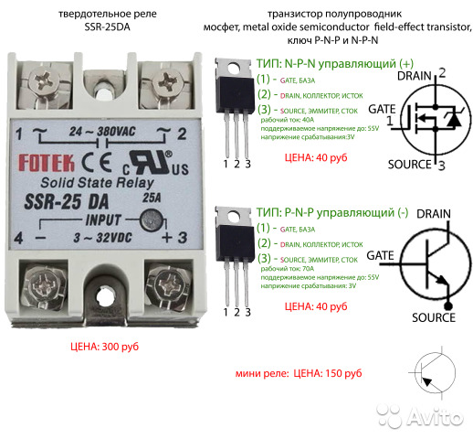
- Darlington transistor
- Advantages and disadvantages
- Solid state - should I use them?
- Purpose and types
- Selection Guide
- Features of the manufacturing process
- Load power control options
- Advantages and disadvantages
- How to make a TTR with your own hands?
- Electronic components for circuit assembly
- Checking the assembled circuit for performance
- Monolithic housing device
- Preparation of the compound and pouring the body
- Classification of solid state relays
- By the number of connected phases
- By type of operating current
- By design features
- By type of control scheme
Darlington transistor
If the load is very powerful, then the current through it can reach
several amps. For high power transistors, the coefficient $\beta$ can
be insufficient. (Moreover, as can be seen from the table, for powerful
transistors, it is already small.)
In this case, you can use a cascade of two transistors. The first
the transistor controls the current, which turns on the second transistor. Such
the switching circuit is called the Darlington circuit.
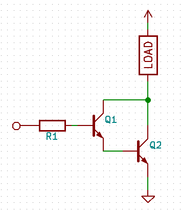
In this circuit, the $\beta$ coefficients of the two transistors are multiplied, which
allows you to get a very high current transfer coefficient.
To increase the turn-off speed of transistors, you can connect each
emitter and base resistor.
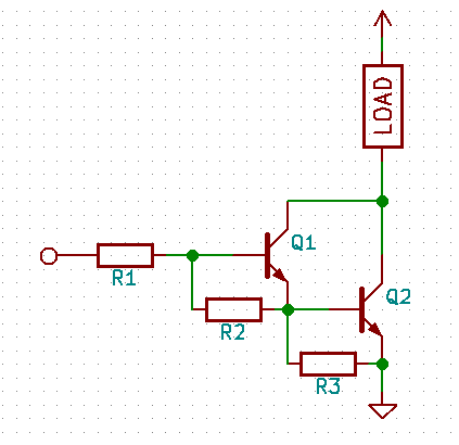
The resistances must be large enough not to affect the current
base - emitter. Typical values are 5…10 kΩ for voltages of 5…12 V.
Darlington transistors are available as a separate device. Examples
such transistors are shown in the table.
| Model | $\beta$ | $\max\ I_{k}$ | $\max\ V_{ke}$ |
|---|---|---|---|
| KT829V | 750 | 8 A | 60 V |
| BDX54C | 750 | 8 A | 100 V |
Otherwise, the operation of the key remains the same.
Advantages and disadvantages
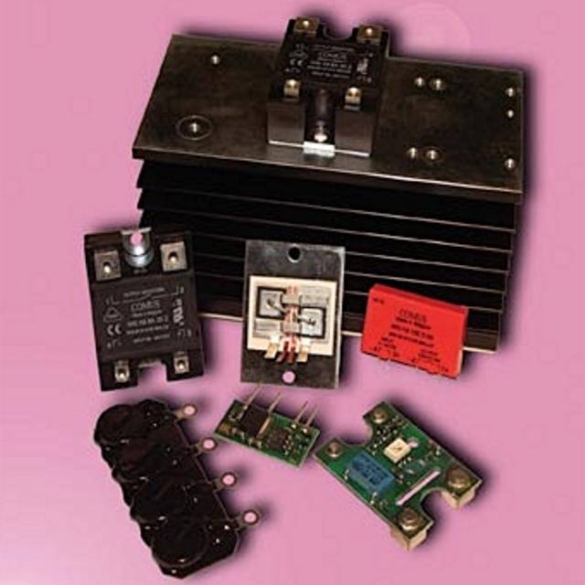
Unlike other types of relays, a solid state relay has no moving contacts. The switching of electrical circuits in this device is carried out according to the principle of an electronic key made on semiconductors. In order to avoid problems when creating a solid-state relay, it is necessary to understand the principle of operation of the device and its design.
However, it is worth starting with a description of its main advantages:
- Ability to switch powerful loads.
- Switching occurs at high speed.
- High-quality galvanic isolation.
- Able to withstand severe overloads in a short time period.
No mechanical relay has similar parameters. The scope of the solid state relay (SSR) is practically unlimited. The absence of moving elements in the design significantly increases the service life of the device. However, it should be remembered that the device has not only advantages. Some properties of SSR are disadvantages. For example, during the operation of powerful devices, it becomes necessary to use an additional element to remove thermal energy.
Often, the dimensions of the radiator significantly exceed the dimensions of the relay itself. In such a situation, the installation of the device is somewhat difficult.When the device is closed, current leakage is observed in it, which leads to the appearance of a non-linear current-voltage characteristic.
Thus, when using an SSR, attention should be paid to the characteristics of the switching voltages. Some types of devices can only work in networks with direct current.
When connecting a solid state relay to a circuit, you need to provide ways to protect against false positives.
Solid state - should I use them?
To begin with, we will also consider the feasibility of using such relays. For example, a real case:
Another case where such relays are not needed:
Overloads and protection of solid state relays will be discussed in detail below, and in this case it is advisable to use a conventional contactor, which copes well with overload and costs 10 times less.
Therefore, it is not worth chasing fashion, but it is better to apply a sober calculation. Calculation of current and finance.


If it comes to someone's mind, you can start a 10 kW engine with a bell button or a reed switch! But it is not so simple, the details will be below.
Purpose and types
A current control relay is a device that responds to sudden changes in the magnitude of the incoming electric current and, if necessary, turns off the power to a certain consumer or the entire power supply system. Its principle of operation is based on comparing external electrical signals and instantaneous response if they do not match the operating parameters of the device. It is used to operate the generator, pump, car engine, machine tools, household appliances and more.
There are such types of devices of direct and alternating current:
- intermediate;
- Protective;
- Measuring;
- pressure;
- Time.
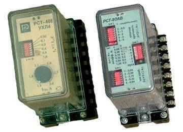
An intermediate device or a maximum current relay (RTM, RST 11M, RS-80M, REO-401) is used to open or close the circuits of a certain electrical network when a certain current value is reached. It is most often used in apartments or houses in order to increase the protection of household equipment from voltage and current surges.
The principle of operation of a thermal or protective device is based on controlling the temperature of the contacts of a certain device. It is used to protect devices from overheating. For example, if the iron overheats, then such a sensor will automatically turn off the power and turn it on after the device cools down.
A static or measuring relay (REV) helps to close the circuit contacts when a certain value of electric current appears. Its main purpose is to compare the available network parameters and the required ones, as well as quickly respond to their changes.
Pressure switch (RPI-15, 20, RPZH-1M, FQS-U, FLU and others) is necessary to control liquids (water, oil, oil), air, etc. It is used to turn off the pump or other equipment when the set indicators are reached pressure. Often used in plumbing systems and at car service stations.
Time delay relays (manufacturer EPL, Danfoss, also PTB models) are needed to control and slow down the response of certain devices when a current leakage or other network failure is detected. Such relay protection devices are used both in everyday life and in industry. They prevent the premature activation of the emergency mode, the operation of the RCD (it is also a differential relay) and circuit breakers.The scheme of their installation is often combined with the principle of including protective equipment and differentials in the network.
In addition, there are also electromagnetic voltage and current relays, mechanical, solid state, etc.
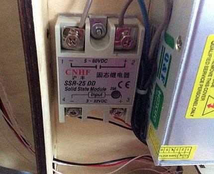
A solid state relay is a single-phase device for switching high currents (from 250 A), providing galvanic protection and isolation of electrical circuits. This is, in most cases, electronic equipment designed to quickly and accurately respond to network problems. Another advantage is that such a current relay can be made by hand.
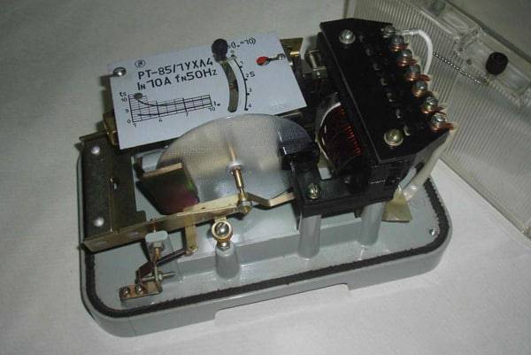
By design, relays are classified into mechanical and electromagnetic, and now, as mentioned above, into electronic ones. Mechanical can be used in various working conditions, it does not require a complex circuit to connect it, it is durable and reliable. But at the same time, not accurate enough. Therefore, now its more modern electronic counterparts are mainly used.
Selection Guide
Due to electrical losses in power semiconductors, solid state relays heat up when the load is switched. This imposes a limitation on the amount of switched current. A temperature of 40 degrees Celsius does not cause a deterioration in the operating parameters of the device. However, heating above 60C greatly reduces the allowable value of the switched current. In this case, the relay may go into an uncontrolled mode of operation and fail.


Therefore, during long-term operation of the relay in nominal, and especially "heavy" modes (with long-term switching of currents above 5 A), the use of radiators is required.At increased loads, for example, in the case of a load of an "inductive" nature (solenoids, electromagnets, etc.), it is recommended to choose devices with a large current margin - 2-4 times, and in the case of controlling an asynchronous electric motor, 6-10 times current margin.
When working with most types of loads, the switching on of the relay is accompanied by a current surge of various duration and amplitude, the value of which must be taken into account when choosing:
- purely active (heaters) loads give the lowest possible current surges, which are practically eliminated when using relays with switching to "0";
- incandescent lamps, halogen lamps, when turned on, pass a current 7 ... 12 times more than the nominal;
- fluorescent lamps during the first seconds (up to 10 s) give short-term current surges, 5 ... 10 times higher than the rated current;
- mercury lamps give a triple current overload during the first 3-5 minutes;
- windings of electromagnetic relays of alternating current: current is 3 ... 10 times more than the rated current for 1-2 periods;
- windings of solenoids: current is 10 ... 20 times more than the nominal current for 0.05 - 0.1 s;
- electric motors: current is 5 ... 10 times more than the rated current for 0.2 - 0.5 s;
- highly inductive loads with saturable cores (transformers at idle) when switched on in the zero voltage phase: the current is 20 ... 40 times the nominal current for 0.05 - 0.2 s;
- capacitive loads when switched on in a phase close to 90°: the current is 20 ... 40 times the nominal current for a time from tens of microseconds to tens of milliseconds.
It will be interesting How is a photorelay used for street lighting?
The ability to withstand current overloads is characterized by the magnitude of the "shock current".This is the amplitude of a single pulse of a given duration (usually 10 ms). For DC relay this value is usually 2–3 times higher than the value of the maximum allowable direct current, for thyristor relays this ratio is about 10. For current overloads of arbitrary duration, one can proceed from an empirical dependence: an increase in the overload duration by an order of magnitude leads to a decrease in the allowable current amplitude. The calculation of the maximum load is presented in the table below.
Table for calculating the maximum load for a solid state relay.
The choice of rated current for a specific load should be in the ratio between the margin of the rated current of the relay and the introduction of additional measures to reduce starting currents (current-limiting resistors, reactors, etc.).
To increase the resistance of the device to impulse noise, an external circuit is placed in parallel with the switching contacts, consisting of a series-connected resistor and capacitance (RC circuit). For more complete protection against the source of overvoltage on the load side, it is necessary to connect protective varistors in parallel with each phase of the SSR.
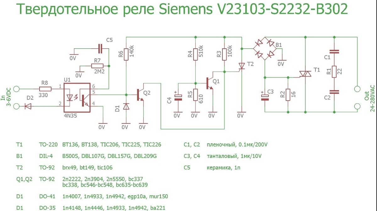
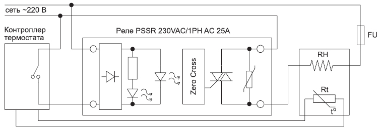
Scheme solid state relay connections.
When switching an inductive load, the use of protective varistors is mandatory. The choice of the required value of the varistor depends on the voltage supplying the load, and is calculated by the formula: Uvaristor = (1.6 ... 1.9) x Uload.
The type of varistor is determined based on the specific characteristics of the device. The most popular domestic varistors are the series: CH2-1, CH2-2, VR-1, VR-2.The solid-state relay provides good galvanic isolation of the input and output circuits, as well as current-carrying circuits from the device's structural elements, so no additional circuit isolation measures are required.
Features of the manufacturing process
The load of the heating element is W.
The input is the primary circuit in which a constant resistance is set.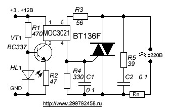
In the usual to bring any electrical mechanism into action, contacts are used that periodically close and open.
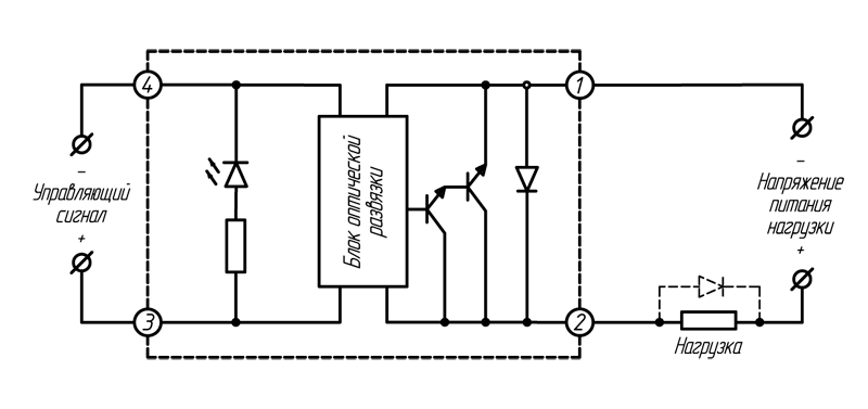
Output power of the order of W. Here in the circuit there are two input options: control input directly to the optocoupler diode and the input signal supplied through the transistor. The switching of electrical circuits in this device is carried out according to the principle of an electronic key made on semiconductors.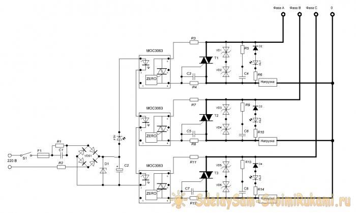
Recommendations for choosing coolers are given in the technical documentation for a specific solid state relay, so it is impossible to give universal advice. Under certain conditions, solid state relays can be used to start induction motors.
Therefore, there is a maximum possible turn-off delay between the removal of the input signal and the disconnection of the load current in one half-cycle. High-quality isolation between control circuits and load. These silent relays are a good replacement for contactors and starters. The same adjustment principle is used in household lighting dimmers.When the DC input voltage signal is removed, the output does not suddenly turn off, because after conduction has been triggered, the thyristor or triac used as a switching device remains on for the remainder of the half cycle until the load currents fall below the current holding devices, at which point it turns off.
Video: solid state relay testing. It is necessary to highlight the following properties of solid state relays: With the help of optical isolation, isolation of various circuits of an electronic device is provided. In solid-state models, this role is played by thyristors, transistors and triacs.
With its help, contacts are attracted. Protection can be located both inside the relay housing and separately
Please note that for triacs, the conclusions are usually ambiguous, so they need to be checked in advance. To apply voltage to the load, a switching circuit is used, which includes a transistor, a silicon diode and a triac
In this example, any preferred resistor value between ohms and ohms will do.
Solid state relay instead of contactor.
Load power control options
Today, there are two main options for power management. Let's consider each and them in more detail:
- PHASE CONTROL. Here, the output signal for I in the load has the form of a sinusoid. The output voltage is set at 10, 50 and 90 percent. The advantages of such a scheme are obvious - the smoothness of the output signal, the ability to connect different types of loads. Minus - the presence of interference in the switching process.
- CONTROL WITH SWITCHING (IN THE PROCESS OF TRANSITION THROUGH ZERO).The advantage of the control method is that during the operation of the solid state relay no interference is created that interferes with the third harmonic during the switching process. Of the shortcomings - limited application. This control scheme is suitable for capacitive and resistive loads. Its use with a highly inductive load is not recommended.
Despite the higher price, solid state relays will gradually replace standard devices with contacts. This is due to their reliability, lack of noise, ease of maintenance and long service life.
Having flaws do not have a negative impact, if you correctly approach the selection and installation of the device.


Advantages and disadvantages
For the manufacture of a solid state relay, you can use chains consisting of a control circuit and a triac. To improve the process of heat dissipation, you should use thermal paste, placing it on the entire contact area of the aluminum base and the semiconductor element. This is because AC switching solid state relays use the SCR and the triac as the output switching device, which continues to conduct after the input is removed until the AC current flowing through the device drops below its threshold or retains its value. current. Suitable for driving resistive, capacitive and inductive loads.
In this case, it is necessary to select a source with sufficient power to turn on the entire relay group.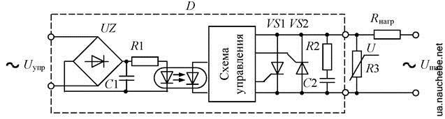
But if the currents are high, there will be a strong heating of the elements.
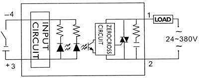
Before trying to make a solid state relay on your own, it is logical to familiarize yourself with the basic design of such devices, to understand the principle of their operation.Scheme for connecting a relay All semiconductor devices of this kind are divided into sections, including: the input part, optical isolation, trigger, as well as switching and protection circuits.
In this case, the peak short-term current values can reach A.
Switching occurs at high speed. Casting compound Advantages and disadvantages Unlike other types of relays, solid state relays do not have moving contacts.
The output circuit of most standard solid state relays is configured to perform only one type of switching action, giving the equivalent of a normally open single pole single pole SPST-NO operating mode of an electromechanical relay. The MOC Opto-Triac Isolator has the same characteristics, but with built-in zero crossing detection, allowing the load to receive full power without large inrush currents when switching inductive loads.
Lecture 357 Solid State Relay

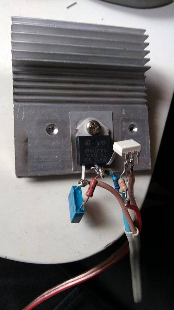
How to make a TTR with your own hands?
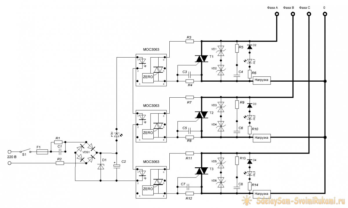
Taking into account the design feature of the device (monolith), the circuit is assembled not on a textolite board, as is customary, but by surface mounting.
There are a lot of circuit solutions in this direction. The specific option depends on the required switching power and other parameters.
Electronic components for circuit assembly
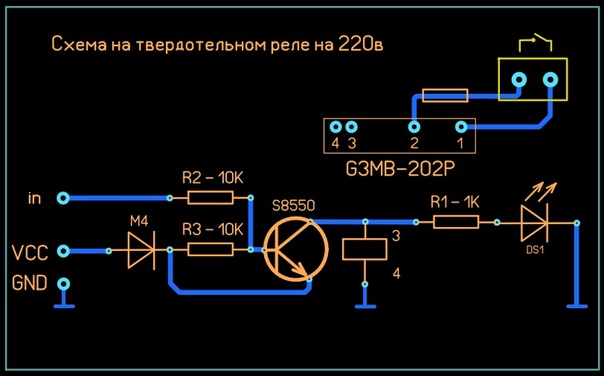
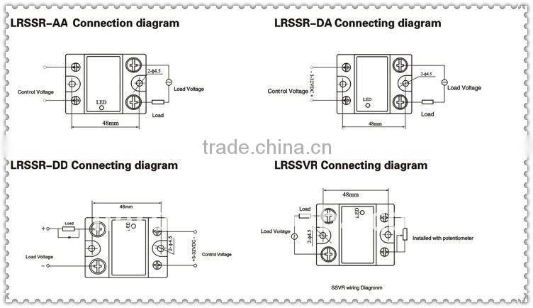
The list of elements of a simple circuit for practical mastering and building a solid-state relay with your own hands is as follows:
- Optocoupler type MOS3083.
- Triac type VT139-800.
- Transistor series KT209.
- Resistors, zener diode, LED.
All specified electronic components are soldered by surface mounting according to the following scheme:
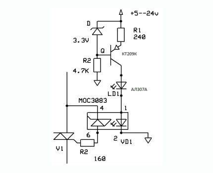
Due to the use of the MOS3083 optocoupler in the control signal generation circuit, the input voltage value can vary from 5 to 24 volts.
And due to the chain consisting of a zener diode and a limiting resistor, the current passing through the control LED is reduced to the minimum possible. This solution ensures a long service life of the control LED.
Checking the assembled circuit for performance
The assembled circuit must be checked for operability. In this case, it is not necessary to connect a load voltage of 220 volts to the switching circuit through a triac. It is enough to connect a measuring device - a tester in parallel with the switching line of the triac.
The measurement mode of the tester must be set to "mOhm" and supply power (5-24V) to the control voltage generation circuit. If everything is working correctly, the tester should show a difference in resistance from "mΩ" to "kΩ".
Monolithic housing device
Under the base of the housing of the future solid-state relay, an aluminum plate 3-5 mm thick will be required. The dimensions of the plate are not critical, but must meet the conditions for efficient heat removal from the triac when this electronic element is heated.
The surface of the aluminum plate must be flat. Additionally, it is necessary to process both sides - clean with fine sandpaper, polish.
At the next stage, the prepared plate is equipped with a “formwork” - a border made of thick cardboard or plastic is glued around the perimeter. You should get a kind of box, which will later be filled with epoxy.
Inside the created box, an electronic circuit of a solid-state relay assembled by a "canopy" is placed. Only the triac is placed on the surface of the aluminum plate.
No other circuit parts or conductors should touch the aluminum substrate. The triac is applied to aluminum with that part of the case, which is designed for installation on a radiator.


Heat-conducting paste should be used on the contact area of the triac housing and the aluminum substrate. Some brands of triacs with an uninsulated anode must be installed through a mica gasket.
The triac must be pressed tightly to the base with some kind of load and poured around the perimeter with epoxy glue or fixed in some way without disturbing the surface of the back side of the substrate (for example, with a rivet).
Preparation of the compound and pouring the body
For the manufacture of a solid body of an electronic device, it will be necessary to make a compound mixture. The composition of the compound mixture is based on two components:
- Epoxy resin without hardener.
- Alabaster powder.
Thanks to the addition of alabaster, the master solves two problems at once - he receives an exhaustive volume of the casting compound at a nominal consumption of epoxy resin and creates a filling of the optimal consistency.
The mixture must be thoroughly mixed, after which the hardener can be added and thoroughly mixed again. Next, the “hinged” installation is carefully poured inside the cardboard box with the created compound.
Filling is done to the upper level, leaving only part of the head of the control LED on the surface. Initially, the surface of the compound may not look completely smooth, but after a while the picture will change. It remains only to wait for the complete solidification of the casting.
In fact, any suitable casting solutions can be used. The main criterion is that the casting composition should not be electrically conductive, plus a good degree of casting rigidity should be formed after solidification. The molded body of the solid state relay is a kind of protection for the electronic circuit from accidental physical damage.
Classification of solid state relays
Relay applications are diverse, therefore, their design features can vary greatly, depending on the needs of a particular automatic circuit. TSR is classified according to the number of connected phases, type of operating current, design features and type of control circuit.
By the number of connected phases
Solid state relays are used both in household appliances and in industrial automation with an operating voltage of 380 V.
Therefore, these semiconductor devices, depending on the number of phases, are divided into:
- single-phase;
- three-phase.
Single-phase SSRs allow you to work with currents of 10-100 or 100-500 A. They are controlled using an analog signal.
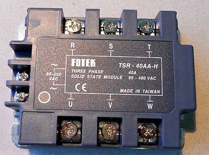
It is recommended to connect wires of different colors to a three-phase relay so that they can be connected correctly when installing equipment
Three-phase solid-state relays are capable of passing current in the range of 10-120 A. Their device assumes a reversible principle of operation, which ensures the reliability of regulation of several electrical circuits at the same time.
Often, three-phase SSRs are used to power an induction motor. Fast fuses are necessarily included in its control circuit due to high starting currents.
By type of operating current
Solid state relays cannot be configured or reprogrammed, so they can only work properly within a certain range of network electrical parameters.
Depending on the needs, SSRs can be controlled by electrical circuits with two types of current:
- permanent;
- variables.
Similarly, it is possible to classify the TTR and by the type of voltage of the active load. Most relays in household appliances operate with variable parameters.


Direct current is not used as the main source of electricity in any country in the world, so relays of this type have a narrow scope
Devices with constant control current are characterized by high reliability and use voltage of 3-32 V for regulation. They withstand a wide temperature range (-30..+70°C) without significant change in characteristics.
Relays controlled by alternating current have a control voltage of 3-32 V or 70-280 V. They are characterized by low electromagnetic interference and high response speed.
By design features
Solid state relays are often installed in the general electrical panel of an apartment, so many models have a mounting block for mounting on a DIN rail.
In addition, there are special radiators located between the TSR and the supporting surface. They allow you to cool the device at high loads, while maintaining its performance.
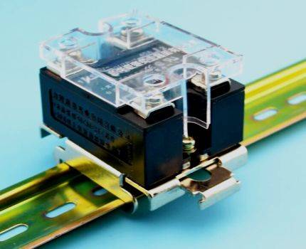
The relay is mounted on a DIN rail mainly through a special bracket, which also has an additional function - it removes excess heat during operation of the device
Between the relay and the heatsink, it is recommended to apply a layer of thermal paste, which increases the contact area and increases heat transfer. There are also TTRs designed for fastening to the wall with ordinary screws.
By type of control scheme
The principle of operation of an adjustable relay of technology does not always require its instantaneous operation.
Therefore, manufacturers have developed several SSR control schemes that are used in various fields:
- Zero control. This option for controlling a solid state relay assumes operation only at a voltage value of 0. It is used in devices with capacitive, resistive (heaters) and weak inductive (transformers) loads.
- Instant. It is used when it is necessary to actuate the relay abruptly when a control signal is applied.
- Phase. It involves the regulation of the output voltage by changing the parameters of the control current. It is used to smoothly change the degree of heating or lighting.
Solid state relays also differ in many other, less significant, parameters.
Therefore, when buying a TSR, it is important to understand the scheme of operation of the connected equipment in order to purchase the most appropriate adjustment device for it.
A power reserve must be provided, because the relay has an operational resource that is quickly consumed with frequent overloads.


