- Hydraulic accumulators, for heating and water supply systems
- Types of accumulators
- 1 Description of sensor and pumping system
- 1.1 Adjusting the pressure switch for the accumulator
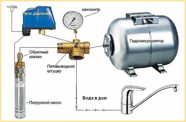
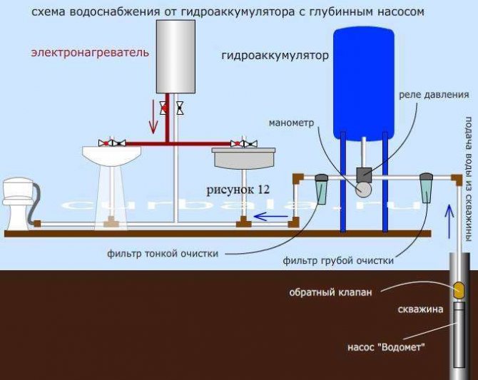
- The principle of operation of the accumulator and the connection of the pump
- Hydraulic accumulator connection diagram for water supply systems
- Option 1
- Option 2
- Option 3
- Operating recommendations
- Hydraulic accumulator device
- We disassemble how to connect a hydraulic accumulator to a submersible pump
- Is it easy to install a hydraulic accumulator
- How to determine the rupture of the membrane?
- Overview of popular models
- Causes of breakdowns and ways to eliminate them
- How a hydraulic accumulator for water supply systems looks and is installed: diagrams
- Setting the accumulator when connected
Hydraulic accumulators, for heating and water supply systems
 Understanding the functions of this device would be incomplete without disclosing its properties in various engineering systems at home. So, the accumulator can be installed:
- In a closed house heating system;
- In the cold water supply system;
- In the hot water supply equipment of the building.
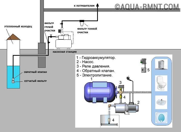
If everything is more or less clear with the role of the accumulator in heating, then in the water supply system the accumulator from an auxiliary device turns into one of the main devices.
The role of the accumulator here is as follows - when water is taken from external sources, a hydrophore is often used, or in another way a pumping station that simulates the operation of a central water supply system. In such a system, as in the central water supply, the necessary pressure is constantly maintained. When the tap is opened, as well as from the central water supply, water begins to flow, and there is no need to separately turn on the pump or preliminarily draw water into a container and place it at a height like a water tower.
The hydrofor is equipped with a hydraulic accumulator, an electric water pump, and a control unit. The pump pumps water into the system, including into the volume of the storage tank, when the automation fixes the required pressure level in the system, it turns off the pump. When the valve is opened, the pressure decreases, but the accumulator squeezes out the required volume of liquid from its volume, maintaining the desired pressure level in the system. If, when a tap was opened, a small amount of water was taken and the pressure did not drop to the minimum value, then the automation does not turn on the pump, if a lot of water has gone, then after a while the automation will turn on the pump and water will be pumped into the pipes from an external source. In this case, the accumulator will be replenished with water again and after a while the automation will turn off the pump.
In the hot water supply system, the accumulator performs a similar function to the one it performs in home heating. In houses where powerful water heating installations are installed, the hydraulic accumulator constantly maintains the set pressure indicator and at the same time protects the system from hydraulic shocks. Together with the safety valve, it is part of the equipment responsible for the correct operation of the boiler.In such installations, when there is no hot water extraction, it circulates in a closed cycle - from the water heater to the end user device, being heated to the required temperature. In order to prevent the spillage of hot water in the system in the event of an accident, a hydraulic accumulator is installed in it, which takes away excess liquid, preventing depressurization of the circuit.
Types of accumulators
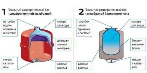
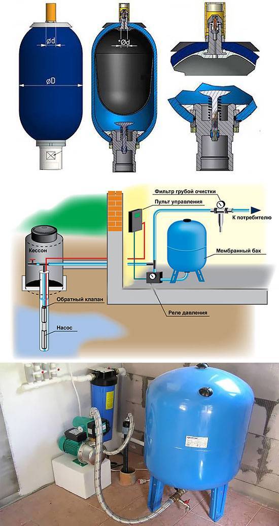
A hydraulic accumulator is a sheet metal tank divided into two parts by an elastic membrane. There are two types of membrane - diaphragm and balloon (pear). The diaphragm is attached across the tank, the balloon in the form of a pear is fixed at the inlet around the inlet pipe.
By appointment, they are of three types:
- for cold water;
- for hot water;
- for heating systems.
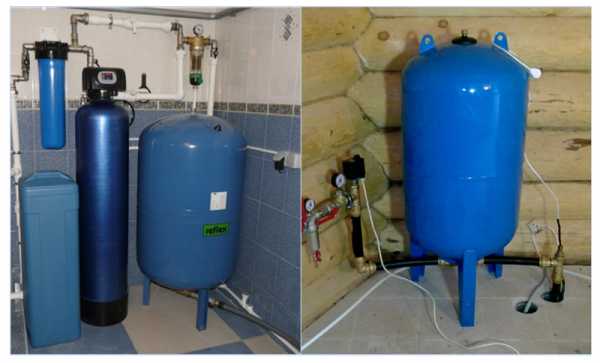
Hydraulic tanks for heating are painted red, tanks for plumbing are painted blue. Expansion tanks for heating are usually smaller and cheaper. This is due to the material of the membrane - for water supply it must be neutral, because the water in the pipeline is drinking.
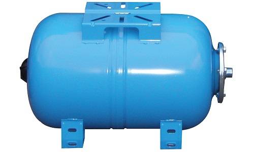
Two types of accumulators
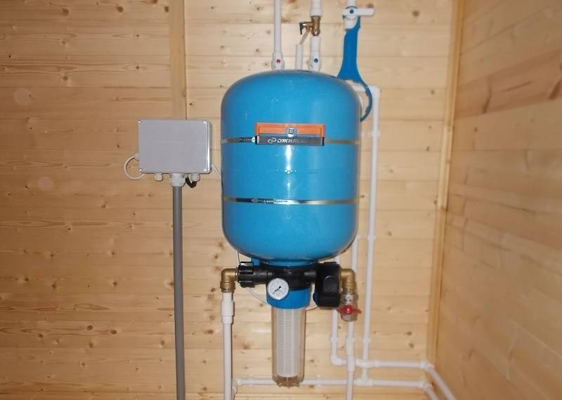
According to the type of location, accumulators are horizontal and vertical. Vertical ones are equipped with legs, some models have plates for hanging on the wall. It is the models that are elongated upwards that are more often used when creating the plumbing systems of a private house on their own - they take up less space. The connection of this type of accumulator is standard - through a 1-inch outlet.
Horizontal models are usually completed with pumping stations with surface-type pumps. Then the pump is placed on top of the tank. It turns out compact.
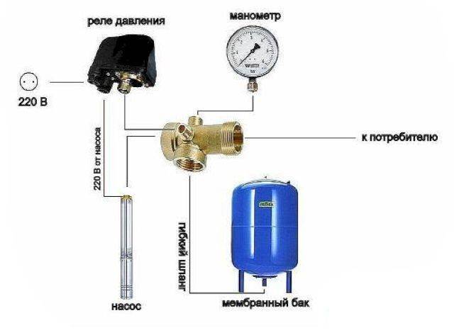
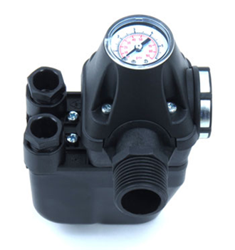
1 Description of sensor and pumping system
The water pressure sensor is an electrical device that regulates the pressure in the accumulator for a pumping station. It also monitors the pressure of the liquid in the pipeline and turns on or off the water supply to the accumulator tank.
This happens due to the short circuit of the wires. Exceeding the allowable threshold opens the contacts and the relay turns off the pump. A drop below the set level closes the contact of the device, including the water supply. You can manually adjust both the upper and lower thresholds.
Scheme of operation of the pressure switch
Basic concepts of a pressure switch for a system with a hydraulic accumulator:
- Rvkl - lower pressure threshold, power on, in standard settings it is 1.5 bar. The contacts are connected, and the pump connected to the relay begins to pump water;
- Roff - the upper pressure threshold, switching off the power supply of the relay, it is better to set it to 2.5-3 bar. The circuit is disconnected and an automatic signal stops the pumps;
- delta P (DR) - an indicator of the pressure difference between the lower and upper thresholds;
- maximum pressure - as a rule, does not exceed 5 bar. This value is displayed in the characteristics of the control device for water supply systems and does not change. Exceeding this will result in damage to the equipment or a reduction in the warranty period.
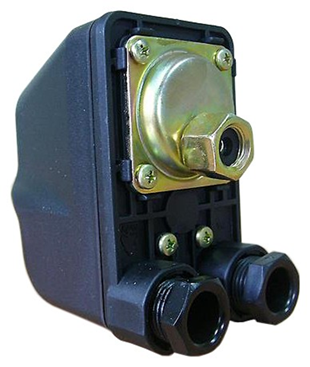
The main element of the pressure switch for the accumulator is a membrane that responds to water pressure. It bends depending on the pressure and tells the mechanism how much the water pressure in the pumping station rises or falls. The bend switches the contacts inside the relay. A special spring counteracts the onslaught of water (which is tightened for adjustment).The smaller spring determines the differential, that is, the difference between the lower and upper pressure thresholds.


Relays can be of two types. The first, power, directly acts on the contacts of the pump. The control type interacts with the automation of the station and through it affects the operation of the pump.
A hydraulic accumulator and a pressure switch form a reliable system for providing water supply to any premises, outbuildings, fields and more. Automation for the pump is also a necessary part - thanks to it, it becomes as simple as possible to control the collection of water and quickly pump liquid into the tank and into the pipes.
Pump station pressure switch device
1.1 Adjusting the pressure switch for the accumulator
Before connecting the equipment to the tank, you should check the operation of the relay and adjust it. It is recommended to take readings with a mechanical pressure gauge. It is more points and less prone to internal breakdowns, due to which its readings may not correspond to reality.
The following will be instructions on how to properly set up the pressure switch. First of all, you need to familiarize yourself with the passport of the device, the pump and the accumulator tank in order to find out the pressure limits for these elements of the pumping station. It is best to familiarize yourself with these parameters when buying and adjust them to each other.
Then proceed in the following order:
- Open the water intake (faucet, hose, valve) so that, thanks to the pressure gauge, you can see the pressure at which the relay trips and the pump turns on. Usually it is 1.5-1 bar.
- Water consumption is turned off to increase the pressure in the system (in the accumulator tank). The pressure gauge fixes the limit at which the relay turns off the pump. Usually it is 2.5-3 bars.
- Adjust the nut attached to the large spring. It defines the value at which the pump is switched on. To increase the switching threshold, tighten the nut clockwise; to decrease it, loosen it (counterclockwise). Repeat the previous points until the switch-on pressure does not correspond to the desired one.
- The switch-off sensor is adjusted with a nut on a small spring. She is responsible for the difference between the two thresholds and the setting principle is the same: to increase the difference (and increase the shutdown pressure) - tighten the nut, to reduce - loosen.
- It is not recommended to turn the nut more than 360 degrees at one time, as they are very sensitive.
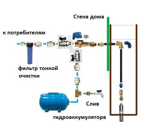
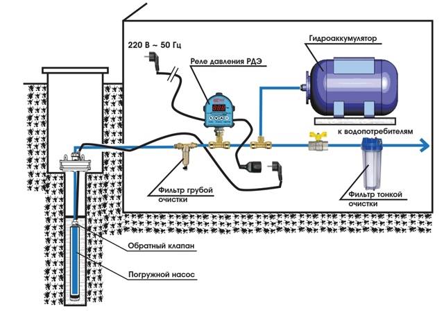
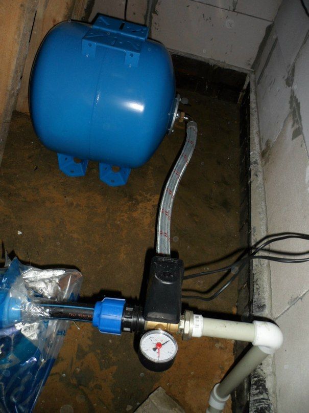
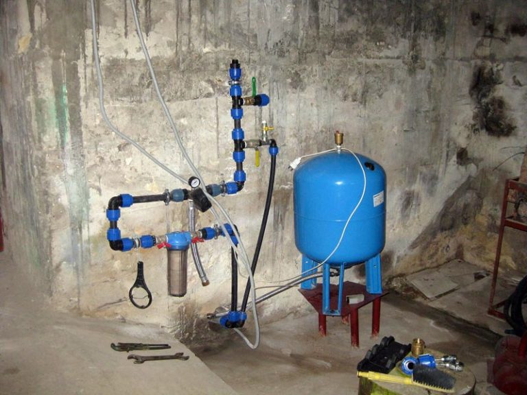
The principle of operation of the accumulator and the connection of the pump
From the well, the pump pumps water into the reservoir of the accumulator through water pipes. The pumping process continues until the pressure reaches the set point. You can adjust the mark on the water pressure switch for the pump.
As a rule, the water pressure switch for the pump is at around 1-3 atm. When the mark is reached, the pump switches itself off. The frequency of switching on and off the pump depends on the capacity of the accumulator.
Installation of the accumulator is carried out by specialists. The housing will not be affected by the position of the device, but installation in rooms with high humidity is undesirable. The installation of the accumulator must be carried out in accordance with the instructions for the device, otherwise the system will fail.Never install devices with visible external damage.
Before installation, decide on the optimal place where the device will stand, take into account the weight of the equipment along with water. There are a number of cases when it may be necessary to urgently drain the water from the accumulator, so this should also be taken care of in advance. The room in which the accumulator will be located must be warm, since freezing of water in it is unacceptable.
Connecting the accumulator takes place in several stages:
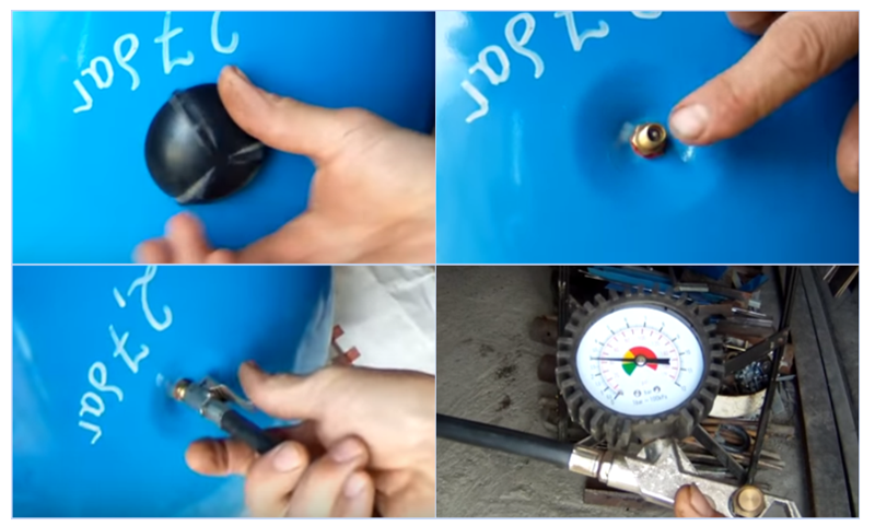
Initially, the pressure is checked, which is created by the air inside the tank, it must be in the range from 0.2-1 bar.
Next, they check the equipment and attach the fitting to the tank
The connection can be a rigid hose.
In turn, attach the remaining elements of the battery, such as a pressure gauge, a relay, a pipe that leads to the pump.
The entire system is tested for leaks, special attention should be paid to the connection points. When turning on the water, you need to monitor the tightness of the threaded connections
To make the fit tighter, you can use a sealant.
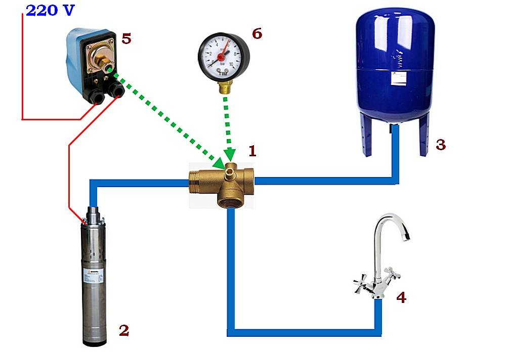
The connection diagram of the pressure switch requires special care
Inside the tank, namely under its cover, there are inscriptions on the contacts "network" and "pump", it is very important not to confuse the wires when connecting the pressure switch to the pump (Fig. 2).
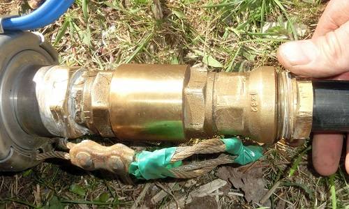
Figure 3. Valve.
The option of connecting a submersible pump to the water supply system is somewhat different from the connection diagram of a hydraulic accumulator for surface-type water supply systems. The submersible pump is fundamentally different from the surface view in that the equipment case is located where the water will be pumped from, it can be a well.In such a system, the valve plays the main role; it is intended to insure the plumbing system from the fact that water will constantly run back into the well (Fig. 3).


First, the valve is installed, and only then they begin to connect the deep pump to the water supply. In accumulators of more than 100 liters, a special valve is used, which is designed to bleed air released from the water. Large pressure can easily damage a single stage valve, so two stage valves and a reinforced connection are used.
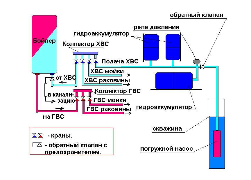
Hydraulic accumulator connection diagram for water supply systems
The method of connecting the GA will depend on the features and purpose of the pumping station. Let's consider three options.
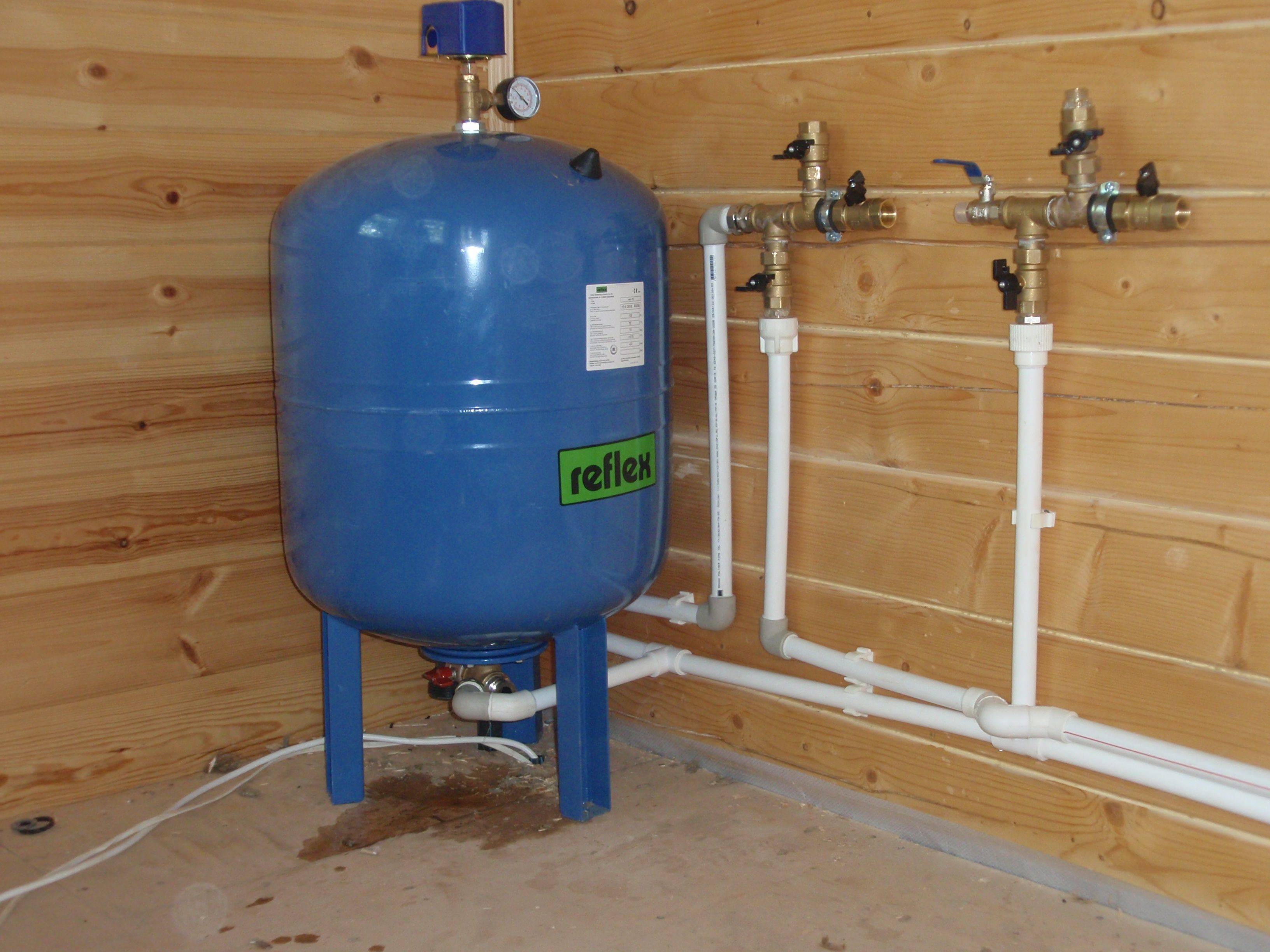
Option 1
The pump supplies water from a well, well or storage tank, while only cold water supply is organized.
In this case, the GA is installed inside the house in any convenient place.
Usually it, a pressure switch and a pressure gauge are connected using a five-pin fitting - a piece of pipe with three outlets that cuts into the water supply.
To protect the GA from vibrations, it is attached to the fitting with a flexible adapter. To check the pressure in the air chamber, as well as to remove air accumulated in the water chamber, the HA must be emptied periodically. Water can be drained through any water tap, but for convenience, a drain valve can be inserted through a tee into the supply pipeline somewhere near the tank.
Option 2
The house is connected to a centralized water supply, and a pumping station is used to increase pressure.With this method of application, the GA stations are connected in front of the pump.
In this case, it is designed to compensate for the decrease in pressure in the external line at the time of starting the electric motor. With such a connection scheme, the volume of the HA is determined by the pump power and the magnitude of pressure surges in the external network.
Installation of a hydraulic accumulator - diagram
Option 3
A storage water heater is connected to the water supply. GA should be connected to the boiler. In this embodiment, it can be used to compensate for the increase in water volume in the heater due to thermal expansion.
Operating recommendations
The most common failure in hydraulic accumulators is a rupture of the rubber membrane. This can happen due to a sharp jump in pressure during injection, or due to wear of the material from long-term operation. The loss of tightness by the membrane will immediately affect the water pressure in the water supply network. It will drop sharply, or start jumping, then increasing, then falling almost to zero.
Only disassembly of the tank body can confirm the rupture of the membrane. At the same time, a new rubber partition is being installed between the internal battery compartments. Step by step the whole process looks like this:
- The accumulator is disconnected from the plumbing system.
- The bolts securing the neck or two halves of the tank are unscrewed (depending on the model).
- The old membrane is removed and replaced with a whole one.
- The body is assembled in the reverse order, the bolts are tightly tightened.
- The device is reconnected to the water supply and put into operation.
- The relay is checked to see if the settings have been lost during the repair work.
This is a general principle of repair, the specific nuances of replacing the membrane may vary for different modifications of the tank.
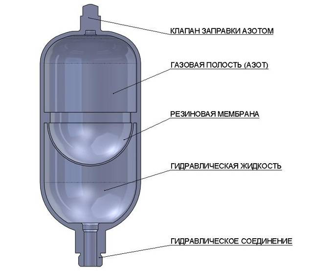
Hydraulic accumulator device
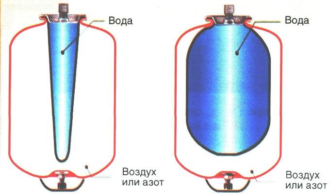
The hermetic case of this device is divided by a special membrane into two chambers, one of which is designed for water, and the other for air.
Water does not come into contact with the metal surfaces of the case, as it is in a water chamber-membrane made of strong butyl rubber material that is resistant to bacteria and meets all hygienic and sanitary standards for drinking water.
In the air chamber there is a pneumatic valve, the purpose of which is to regulate pressure. Water enters the accumulator through a special threaded connection pipe.


The accumulator device must be mounted in such a way that it can be easily disassembled in case of repair or maintenance, without draining all the water from the system.
The diameters of the connecting pipeline and the discharge pipe should, if possible, match each other, then this will avoid unwanted hydraulic losses in the system pipeline.
In the membranes of accumulators with a volume of more than 100 liters, there is a special valve for bleeding air released from the water. For small-capacity accumulators that do not have such a valve, a device for bleeding air must be provided in the water supply system, for example, a tee or a tap that shuts off the main line of the water supply system.
In the air valve of the accumulator, the pressure should be 1.5-2 atm.
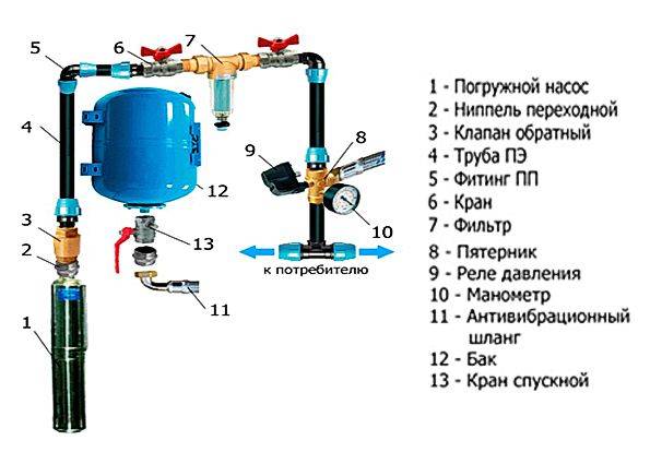
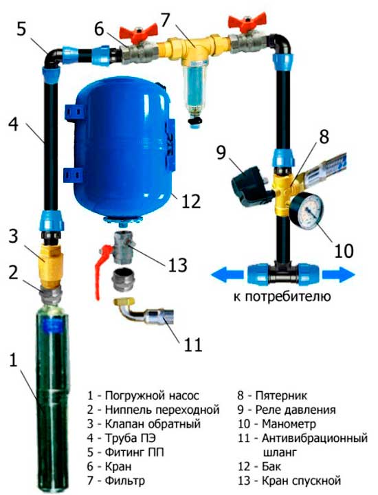
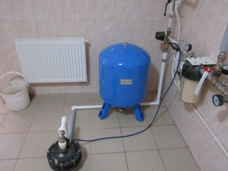
We disassemble how to connect a hydraulic accumulator to a submersible pump
In order to properly connect the accumulator to the submersible pump, you first need to theoretically understand the connection mechanism. This will help to quickly complete the work of connecting the pump to the tank.
Connecting the accumulator to the water supply system is not difficult. To do this, it is enough to have all the necessary elements, valves, hoses and connect them sequentially according to the algorithm.
In order to connect the tank, it will be necessary to check the presence of:
Downhole pump;
Relay;
Pipelines for the flow of water from the pump to the future tank and from the tank to water intake points;
check valve;
Stop valves;
Filters for water purification;
Drainage for sewerage.

If you have all of the above, then you can start connecting. An adapter nipple is connected to the submersible pump. Next is the connection of the check valve and pipe. Then a fitting and a filter are placed, and a tap between them. After them, install the fiver and pressure switch. A manometer is required for control. It helps to set the pressure. Connect a drain valve and a hose to the accumulator that can withstand vibration during operation. This completes the installation. In this case, the well fades into the background, because all the main work is transferred to the home water supply system.
Connecting the battery to the pump is not difficult. The main thing is to check the availability of all components for connection to a submersible or borehole pump. Otherwise, you will have to turn off the work. The connection process can only take a couple of hours if you do it in the correct sequence.
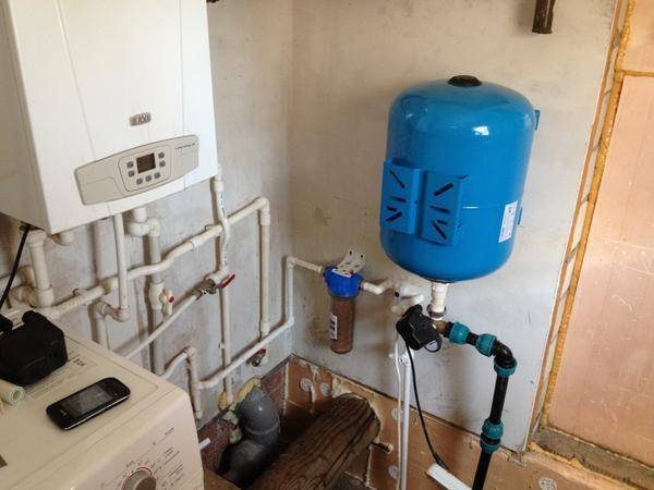
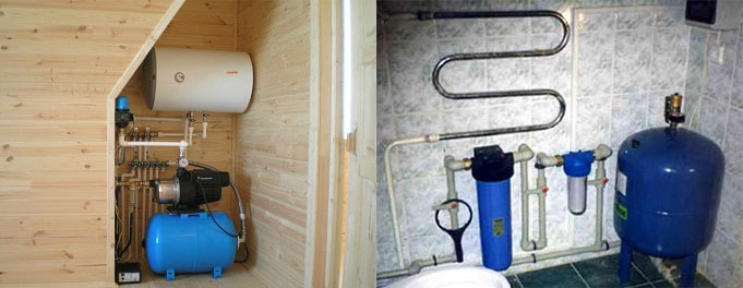
Is it easy to install a hydraulic accumulator
Summer residents immediately panic when they hear that the accumulator must be connected to the water supply system. They think that pipes can suddenly burst and then the entire summer cottage, together with the house, will be filled with water. This is not true.
The installation of the accumulator takes place according to the standard and proven scheme. A lot of summer residents integrated their tanks along it. And they did an excellent job. To do this, they purchased all the necessary components in the form of nipples, pumps and fittings.
To put it in the right place, you need to determine the water flow parameter for the whole house. Determine the power of the pump and the volume of the accumulator. It is also worth knowing the location of the main water supply units.


Next, you must write a list of what you need to buy to install the tank:
- hoses;
- Pipes;
- Fitting;
- Nipples;
- Cranes and so on.
Then look at the installation diagram and just do everything as indicated there.
At first glance, it seems that installing a tank is a difficult task. This is not true. Decide on a place, look at the schemes that the water supply has. Buy the connection parts and simply connect the tank to the general water supply.
How to determine the rupture of the membrane?
Another common problem is the rupture of the internal membrane of the accumulator. The membrane is made of very durable rubber, and is able to withstand several years of service, periodically filling with water and shrinking, squeezing water into the pipeline network. However, any part has a tensile strength and a certain service life. Over time, the membrane can lose its elasticity and strength, eventually bursting.Direct evidence of a rupture of the membrane are the following signs:
- The pressure in the system is not uniform. The faucet spits out water in batches.
- The pressure gauge needle of the accumulator moves abruptly, from maximum to minimum.
To make sure that the membrane is broken, bleed the air from the spool from the back of the tank. If water escapes along with the air filling the membrane space, then the rubber partition is definitely broken and needs to be replaced. It is quite possible to change the membrane with your own hands. To do this, purchase a new membrane in a plumbing store. When buying, make sure that the rubber component is from your hydraulic tank model.
Then we disassemble the accumulator by unscrewing the connecting bolts. The torn part is removed and a new membrane is put in its place. Then the tank is assembled, and all connecting bolts are evenly and firmly tightened.
Overview of popular models
There are two types of pressure switches: mechanical and electronic, the latter are much more expensive and rarely used. A wide range of devices from domestic and foreign manufacturers is presented on the market, facilitating the choice of the required model.
RDM-5 Dzhileks (15 USD) is the most popular high-quality model from a domestic manufacturer.
Characteristics
- range: 1.0 - 4.6 atm.;
- minimum difference: 1 atm.;
- operating current: maximum 10 A.;
- protection class: IP 44;
- factory settings: 1.4 atm. and 2.8 atm.
Genebre 3781 1/4″ ($10) is a Spanish-made budget model.
Genebre 3781 1/4″
Characteristics
- case material: plastic;
- pressure: top 10 atm.;
- connection: threaded 1.4 inches;
- weight: 0.4 kg.
Italtecnica PM / 5-3W (13 USD) is an inexpensive device from an Italian manufacturer with a built-in pressure gauge.
Characteristics
- maximum current: 12A;
- working pressure: maximum 5 atm.;
- lower: adjustment range 1 - 2.5 atm.;
- upper: range 1.8 - 4.5 atm.


Causes of breakdowns and ways to eliminate them
Despite a fairly strong and durable design, it happens that the accumulator for water supply fails. There are several reasons for this. Very often there is airing of the water line. An air lock is formed in the pipeline, which prevents the normal circulation of water. The cause of airing the water supply is the accumulation of air inside the membrane. It gets there along with the flow of water, and gradually accumulates, spreading through the pipeline.
In hydraulic tanks with a vertical installation method, a special drain nipple is installed in their upper part to bleed the air accumulated in the membrane. Small drives, with a volume of less than 100 liters, are usually carried out in a horizontal pattern. Blowing air into them can be a little more difficult.
The procedure here is carried out in several stages:
- The hydraulic accumulator is disconnected from the power supply.
- All water is drained from the system until the storage tank is completely empty.
- Then all valves in the pipeline system are closed.
- The hydraulic tank is connected to electricity and refilled with water.
The air accumulated inside the accumulator will leave together with the discharged water.
How a hydraulic accumulator for water supply systems looks and is installed: diagrams
The hydraulic accumulator for water supply systems allows you to minimize possible accidents in the water supply system.This device helps to solve many problems, and even if there is a power failure on your site, you will always have a small supply of water in the tank.
Almost all owners of country houses know how dangerous pressure surges in the water supply network are and how difficult it is to predict when the next failure will occur in order to avoid damage to household appliances connected to the water supply. This problem will also help to solve the installation of a hydraulic accumulator. Such devices are also used in autonomous heating systems.
Setting the accumulator when connected
Before using a water supply system with a hydraulic accumulator in a private house, you need to know what the pressure in the accumulator should be for its optimal operation; a portable pressure gauge is taken to take readings. A typical water line with a standard pressure switch has response thresholds from 1.4 to 2.8 bar., The factory setting of the pressure in the hydraulic tank is 1.5 bar. In order for the operation of the accumulator to be efficient and to be completely filled, for a given factory setting, the lower threshold for turning on the electric pump is selected by 0.2 bar. more - a threshold of 1.7 bar is set on the relay.
If in the hydraulic tank during operation or due to a long storage period, when measuring with a pressure gauge, it is determined that the pressure is insufficient, proceed as follows:
- Disconnect the electric pump from the power supply.
- Remove the protective cover and press the valve of the hydraulic tank in the form of a nipple head at the outlet of the device - if liquid flows from there, then the rubber membrane has been damaged and must be changed. If air enters from the hydraulic tank, its pressure is measured using a car pressure gauge.
- Drain the water from the line by opening the valve closest to the expansion tank.
- Using a hand pump or compressor, air is pumped into the storage tank until the pressure gauge reads 1.5 bar. If, after automation, water rises to a certain height (high-rise buildings), the total pressure and the operating range of the system are increased based on the fact that 1 bar. equate to 10 meters of vertical water column.